Gas Metal Arc Welding (GMAW), commonly known as MIG welding, stands as one of the most versatile and widely adopted welding processes across industries worldwide. From automotive manufacturing to construction, shipbuilding to aerospace, MIG welding’s adaptability makes it indispensable for both professionals and hobbyists alike.
At the heart of this process lies a critical concept that directly influences weld quality, productivity, and application suitability: metal transfer mode. Understanding these transfer modes is essential for any welder looking to optimize their welding parameters, achieve superior results, and select the right technique for each unique application.
This comprehensive guide explores the four primary metal transfer modes in GMAW welding, examining their mechanisms, characteristics, advantages, limitations, and optimal use cases.
What is Metal Transfer in GMAW Welding?
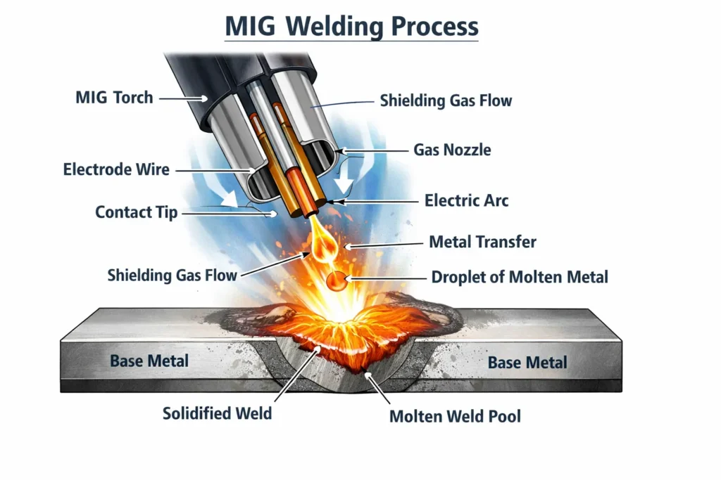
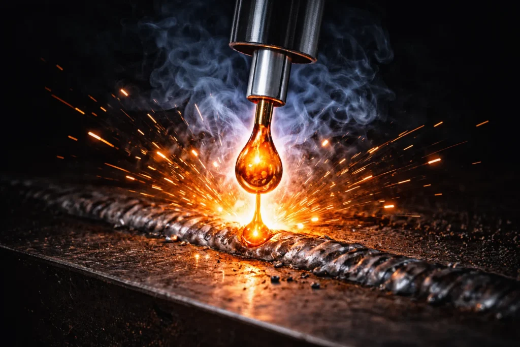
Metal transfer refers to the mechanism by which molten electrode material crosses the arc gap and deposits into the weld joint. In GMAW welding, a continuously fed consumable wire electrode serves dual purposes: it creates the electrical arc and provides filler material to form the weld bead.
The transfer process begins when electrical current flows through the contact tip to the electrode wire, establishing an arc as the wire approaches the base metal. The intense heat from this arc (which can exceed 10,000°F or 5,500°C) melts both the electrode wire and the base material. The molten electrode material must then transfer across the arc gap to fuse with the base metal.
Factors Influencing Metal Transfer Mode
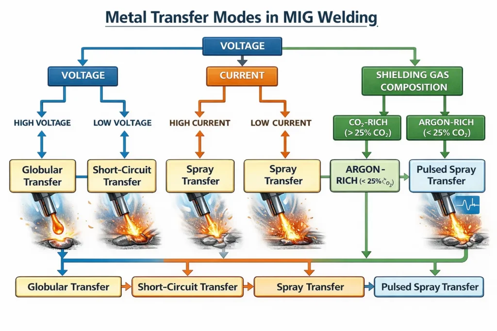
The manner in which this transfer occurs depends on several interrelated parameters:
Electrical Parameters:
- Current (Amperage): Controlled indirectly through wire feed speed in constant voltage systems
- Voltage: Determines arc length and heat input
- Electrode Polarity: GMAW typically uses Direct Current Electrode Positive (DCEP)
Material Parameters:
- Wire Diameter: Ranging from 0.023″ to 0.062″ for most applications
- Wire Composition: Steel, aluminum, stainless steel, or specialty alloys
- Base Metal Thickness: From thin sheet metal to heavy structural plate
Shielding Gas Composition:
- Pure gases: Argon, Helium, CO₂
- Binary mixtures: Argon/CO₂ (most common: 75/25, 90/10, 95/5)
- Ternary mixtures: Argon/CO₂/Oxygen for specific applications
These variables work together to create distinct transfer modes, each with unique characteristics and optimal applications.
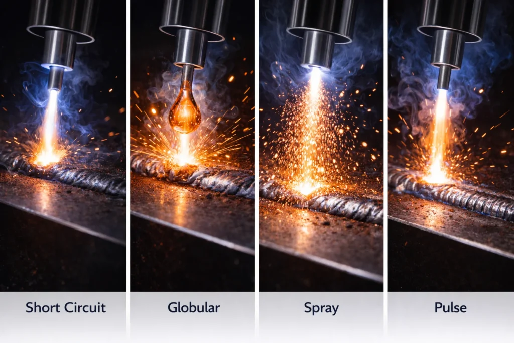
The Four Primary Metal Transfer Modes in GMAW
1. Short Circuit Transfer (GMAW-S)
Short circuit transfer represents the lowest energy transfer mode in GMAW welding and is characterized by a distinctive cyclic process that occurs between 20 to 200 times per second.
The Short Circuit Cycle
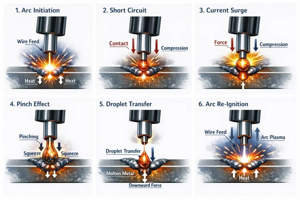
The transfer mechanism follows a predictable sequence:
- Arc Initiation: The electrode wire approaches the weld pool under constant wire feed
- Contact: The wire tip touches the molten pool, creating a short circuit that extinguishes the arc
- Current Surge: The short circuit causes a rapid increase in current
- Pinch Effect: Electromagnetic forces create a “pinch” that constricts the wire
- Droplet Transfer: A small droplet separates from the wire and joins the weld pool
- Arc Re-ignition: The arc re-establishes as the wire pulls away from the pool
- Cycle Repetition: The process repeats continuously
This rapid cycling produces the characteristic “bacon frying” sound associated with short circuit MIG welding.
[IMAGE PLACEMENT 3: Sequential illustration of the short circuit transfer cycle]
Operating Parameters
Typical Settings:
- Voltage: 16-20 volts
- Current: 50-200 amperes (depending on wire diameter and material)
- Wire Feed Speed: 100-400 inches per minute
- Wire Diameter: 0.023″, 0.030″, 0.035″ (most common)
Shielding Gas Options:
- 75% Argon / 25% CO₂ (C25): Most popular for steel, good arc stability
- 85% Argon / 15% CO₂: Reduces spatter, smoother arc
- 100% CO₂: Most economical, increased spatter, deeper penetration
Advantages of Short Circuit Transfer
1. Thin Material Capability The low heat input makes short circuit transfer ideal for materials from 24 gauge up to 1/4 inch (6mm) thickness. The controlled energy prevents burn-through and minimizes distortion on thin panels.
2. All-Position Welding The fast-freezing weld pool allows welding in vertical, horizontal, and overhead positions. The small droplet size and rapid solidification prevent the molten metal from sagging or dripping.
3. Gap-Filling Ability Short circuit transfer tolerates poor fit-up better than other modes, making it suitable for repair work and applications where precise joint preparation is challenging.
4. Lower Equipment Cost Standard MIG welders without pulse or synergic capabilities can perform short circuit transfer effectively.
5. Versatile Gas Options Short circuit works with both economical CO₂ and premium Argon mixtures, providing flexibility based on budget and application requirements.
Limitations and Challenges
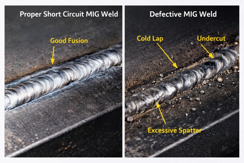
1. Cold Lap and Lack of Fusion The relatively low heat input can cause incomplete fusion, particularly on thicker materials or when welding too quickly. Cold lap occurs when the filler metal doesn’t properly fuse with the base metal sidewalls.
2. Spatter Generation The violent nature of the short circuit and arc re-ignition creates spatter. Modern inverter machines with waveform control significantly reduce this issue compared to older transformer-based equipment.
3. Limited Deposition Rate Compared to spray transfer, short circuit provides slower metal deposition, reducing productivity on heavy fabrication projects.
4. Undercut Risk Improper technique or excessive voltage can create undercut along the weld toe, particularly in vertical and overhead positions.
5. Weld Appearance While functional, short circuit welds typically show more surface irregularity than spray or pulse modes.
[IMAGE PLACEMENT 4: Photo comparison showing proper vs. improper short circuit welds with labeled defects]
Best Applications for Short Circuit Transfer
- Automotive body panel repair and fabrication
- Sheet metal HVAC ductwork
- Thin-wall tubing and pipe
- General fabrication on materials under 1/4 inch
- Root pass welding on pipe
- Out-of-position welding on light gauge material
2. Globular Transfer
Globular transfer occurs when current levels exceed short circuit thresholds but remain below the transition to spray transfer. This mode is characterized by large, irregular droplets of molten metal that transfer across the arc gap.
The Globular Transfer Mechanism
Unlike the controlled short circuit cycle, globular transfer creates droplets that are typically larger than the electrode wire diameter. These “globs” form at the wire tip due to gravitational and electromagnetic forces. When the droplet becomes large enough, gravity (in flat and horizontal positions) or electromagnetic forces overcome surface tension, and the droplet falls or is propelled across the arc into the weld pool.
The transfer frequency is much lower than short circuit (often just 1-10 drops per second), and the process can be erratic and less controlled.
Operating Parameters
Typical Settings:
- Voltage: 20-28 volts
- Current: 200-300 amperes
- Wire Feed Speed: 300-600 inches per minute
- Wire Diameter: 0.035″, 0.045″, 0.052″
Shielding Gas:
- 100% CO₂: Most common for globular transfer on carbon steel
- Argon/CO₂ mixtures: Can be used but may not provide advantages
- Not recommended with high Argon content: High Argon promotes spray transfer at these current levels
Advantages of Globular Transfer
1. Deep Penetration The high current and large droplet mass provide excellent penetration, making globular transfer effective for thicker materials and heavy sections.
2. High Deposition Rate Compared to short circuit, globular transfer deposits significantly more filler metal per unit time, increasing productivity.
3. Economical Operation with CO₂ Using 100% CO₂ shielding gas makes this the most economical GMAW process in terms of gas cost.
4. Simple Equipment Requirements Any conventional MIG welder can perform globular transfer without special features or controls.
Limitations and Challenges
1. Excessive Spatter Globular transfer produces the most spatter of any transfer mode. The large, heavy droplets create violent reactions when they impact the weld pool, ejecting molten metal.
2. Position Limitations The large, fluid weld pool and gravity-dependent transfer restrict globular welding to flat and horizontal positions only. Vertical and overhead welding is not practical.
3. Poor Weld Appearance The combination of heavy spatter, irregular bead profile, and rough surface finish make globular transfer unsuitable when weld aesthetics matter.
4. Inconsistent Transfer The irregular nature of droplet formation and transfer can create an unstable arc and inconsistent weld quality.
5. Increased Heat Input The high current creates significant heat input, which can cause distortion on thinner materials and increase the heat-affected zone (HAZ).
Best Applications for Globular Transfer
- Heavy structural steel welding in flat position
- High-deposition welding where appearance is not critical
- Thick plate welding requiring deep penetration
- Applications where CO₂ economy is prioritized
- Welding dirty or rusty steel where penetration helps overcome contamination
In modern welding practice, globular transfer is less commonly used intentionally. Many welders avoid the globular range entirely, transitioning directly from short circuit to spray transfer by adjusting parameters and shielding gas composition.
3. Spray Transfer (GMAW-P)
Spray transfer represents a significant advancement in metal transfer technology and produces some of the highest quality GMAW welds. When sufficient current and voltage combine with an argon-rich shielding gas, the transfer mode transitions from globular to a fine spray of tiny droplets.
The Spray Transfer Mechanism
In spray transfer, hundreds of tiny droplets (smaller than the electrode wire diameter) transfer across the arc per second in a highly directional stream. The mechanism operates through axial spray, where electromagnetic forces accelerate the droplets along the electrode axis directly into the weld pool.
The transition from globular to spray occurs at the transition current, which varies based on:
- Wire diameter (larger wires require higher transition current)
- Wire material composition
- Shielding gas argon content (minimum 80% typically required)
Once above the transition current, the transfer becomes extremely stable, producing a characteristic smooth, hissing sound quite different from the crackling of short circuit transfer.
Operating Parameters
Typical Settings:
- Voltage: 26-32 volts
- Current: 250-450+ amperes (above transition current)
- Wire Feed Speed: 400-700+ inches per minute
- Wire Diameter: 0.035″, 0.045″, 0.052″, 0.062″
Shielding Gas Requirements:
- Minimum 80% Argon: Required to achieve and maintain spray transfer
- 90% Argon / 10% CO₂: Popular balance of arc stability and penetration
- 95% Argon / 5% O₂: Excellent for stainless steel
- 98% Argon / 2% CO₂: Very smooth arc, minimal spatter
- 100% Argon: Used for aluminum and non-ferrous metals
Advantages of Spray Transfer
1. Minimal Spatter The fine, directed spray produces virtually no spatter when properly adjusted, eliminating post-weld cleanup time.
2. High Deposition Rates Spray transfer deposits more filler metal per minute than any other GMAW mode (except pulse at peak parameters), significantly increasing productivity.
3. Superior Weld Appearance The stable arc and smooth transfer create attractive, uniform weld beads with excellent surface finish.
4. Deep, Consistent Penetration High current and focused energy concentration provide excellent fusion and penetration uniformity.
5. Stable Arc Characteristics The axial spray mode creates an exceptionally stable arc that’s easy to control and produces consistent results.
6. Excellent for Thicker Materials Spray transfer excels on materials 1/8 inch (3mm) and thicker, with no upper thickness limitation.
Limitations and Challenges
1. Position Restrictions The extremely fluid weld pool limits spray transfer to flat and horizontal positions only. The high heat input prevents adequate puddle control in vertical or overhead positions.
2. Argon Gas Requirement The need for minimum 80% argon shielding gas increases operating costs compared to CO₂ or low-argon mixtures.
3. Not Suitable for Thin Materials The high heat input makes spray transfer impractical for materials thinner than 1/8 inch due to burn-through and distortion risks.
4. Higher Equipment Requirements Achieving spray transfer requires welders capable of delivering sufficient current, though most modern machines meet this requirement.
5. Transition Current Threshold Operating just below the transition current produces poor results. Welders must ensure parameters exceed this threshold or use a different transfer mode.
Best Applications for Spray Transfer
- Heavy structural steel fabrication
- Pressure vessel and tank manufacturing
- Thick aluminum welding in aerospace and marine applications
- Stainless steel food processing equipment
- High-production manufacturing requiring maximum deposition
- Applications where weld appearance and minimal spatter are critical
Spray transfer dominates in industrial settings where its advantages in productivity, quality, and consistency justify the higher gas costs.
4. Pulsed Spray Transfer (GMAW-P)
Pulsed spray transfer represents the most sophisticated and versatile GMAW transfer mode, combining the best characteristics of all other modes while minimizing their limitations. This technology emerged from research aimed at creating a universal transfer mode suitable for all positions, materials, and thicknesses.
The Pulse Mechanism
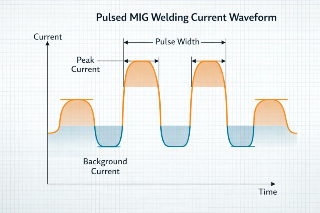
Pulsed MIG operates by rapidly cycling the welding current between two distinct levels:
1. Peak Current (Pulse Phase)
- Duration: 1-10 milliseconds
- Current level: Above spray transfer transition current
- Purpose: Melts wire and creates one controlled droplet per pulse
- Result: Axial spray transfer of single droplet
2. Background Current (Base Phase)
- Duration: 1-20 milliseconds
- Current level: Below transition current, above minimum arc maintenance
- Purpose: Maintains arc, allows weld pool to cool slightly
- Result: No metal transfer occurs
This cycle repeats at frequencies typically between 30-400 Hz (pulses per second), with modern synergic machines automatically calculating optimal parameters based on wire feed speed and material.
Operating Parameters
Typical Settings (Synergic Control):
- Wire Feed Speed: Set by welder, machine calculates other parameters
- Peak Current: Automatically calculated (typically 300-500A)
- Background Current: Automatically calculated (typically 30-100A)
- Pulse Frequency: Automatically calculated (30-400 Hz)
- Voltage: Automatically optimized (typically 22-30V)
Manual Pulse Settings:
- Peak Current: Set above transition for wire diameter
- Background Current: 25-50% of peak current
- Pulse Frequency: Adjusted for desired bead appearance
- Pulse Width: Typically 20-80% duty cycle
Shielding Gas:
- 90% Argon / 10% CO₂: Most popular for carbon steel
- 92% Argon / 8% CO₂: Excellent balance for steel
- 95-98% Argon / 2-5% CO₂: Very low spatter applications
- 100% Argon: Aluminum and non-ferrous metals
Advanced Pulse Technology: Double Pulse
Double pulse (also called pulse-on-pulse) adds a secondary modulation to the primary pulse sequence:
Primary Pulse: Controls metal transfer (hot/cold cycling) Secondary Pulse: Modulates the average power (high/low power cycling)
The secondary pulse creates a distinctive rippled or “stacked dimes” bead appearance by alternating between higher and lower average heat input. This thermal cycling provides:
- Enhanced mechanical properties through refined grain structure
- Distinctive aesthetic appeal
- Reduced total heat input
- Better control on thin materials
Advantages of Pulsed Transfer
1. All-Position Capability The controlled heat input and background current cooling allows successful welding in all positions including vertical and overhead.
2. Versatile Material Range Pulse welding handles everything from thin sheet metal (24 gauge) to unlimited thickness heavy plate with appropriate parameter adjustment.
3. Minimal Spatter Controlled one-drop-per-pulse transfer nearly eliminates spatter, reducing cleanup time and material waste.
4. Superior Weld Quality The controlled heat cycling produces excellent fusion, minimal porosity, and refined weld metal microstructure.
5. Excellent Arc Stability The pulsing action creates an exceptionally stable, easy-to-control arc even on challenging materials.
6. Reduced Heat Input Compared to continuous spray transfer, pulse provides lower average heat input, minimizing distortion and HAZ.
7. No Cold Lap Issues Peak current ensures proper fusion, eliminating the cold lap problems associated with short circuit transfer.
8. Enhanced Productivity While not always faster than spray, pulse offers better efficiency through reduced rework, cleanup, and defect rates.
Limitations and Challenges
1. Equipment Cost Pulse-capable MIG welders cost more than conventional machines, though prices have decreased with modern inverter technology.
2. Argon Gas Requirement Like spray transfer, pulse requires minimum 80% argon shielding gas for proper operation.
3. Parameter Complexity Manual pulse welding requires understanding and adjusting multiple parameters. However, modern synergic machines largely eliminate this challenge.
4. Learning Curve Optimizing pulse parameters for specific applications takes experience, though synergic programs simplify this significantly.
5. Overkill for Simple Applications For basic short circuit welding on thin materials, the added capability may not justify the equipment investment.
Synergic Pulse Control
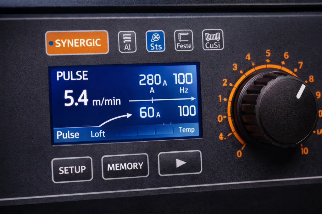
Modern pulse MIG welders feature synergic control systems that revolutionize ease of use:
How Synergic Control Works:
- Welder selects material type and wire diameter
- Welder sets only wire feed speed
- Machine automatically calculates and adjusts:
- Peak current
- Background current
- Pulse frequency
- Pulse width
- Voltage
- Arc length correction
This “one-knob” welding makes pulse technology accessible to less experienced welders while allowing experts to fine-tune specific parameters for optimized results.
Best Applications for Pulsed Transfer
Automotive and Transportation:
- Aluminum automotive components
- Frame repair and fabrication
- Thin body panel welding
Aerospace:
- Aluminum airframe components
- Thin-wall tubing
- Critical structural joints
Manufacturing:
- Stainless steel food equipment
- Precision fabrication
- Multi-position welding requirements
General Fabrication:
- Mixed material thickness projects
- Out-of-position welding needs
- Applications requiring minimal cleanup
- Situations where weld appearance matters
Pipe Welding:
- All-position pipe fabrication
- Orbital welding systems
- Root, fill, and cap passes
Selecting the Optimal Transfer Mode
Choosing the appropriate metal transfer mode requires analyzing multiple project factors:
Decision Matrix
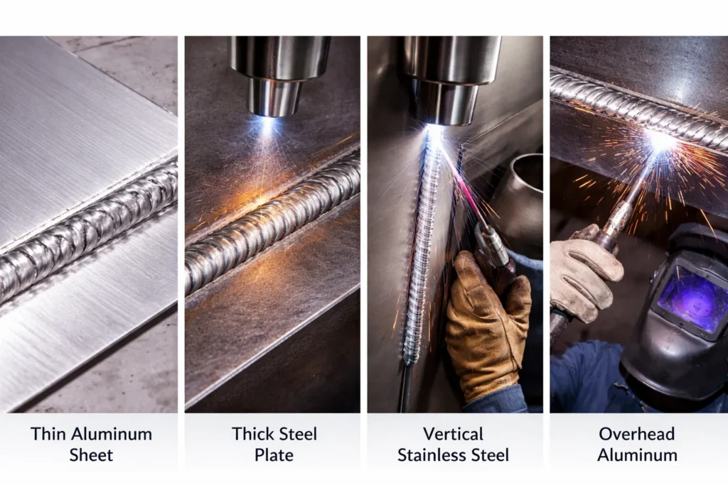
Material Thickness:
- Under 1/8″: Short circuit or pulse
- 1/8″ to 1/4″: Short circuit, pulse, or spray (flat position)
- Over 1/4″: Spray or pulse (globular if economics dictate)
Welding Position:
- Flat and Horizontal: Any mode
- Vertical and Overhead: Short circuit or pulse only
Material Type:
- Carbon Steel: All modes
- Stainless Steel: Preferably spray or pulse
- Aluminum: Spray or pulse only
- Silicon Bronze: Short circuit preferred
Quality Requirements:
- Appearance Critical: Spray or pulse
- Structural Integrity: Spray or pulse
- Economy/Speed Priority: Spray (flat) or short circuit
Deposition Requirements:
- Maximum Productivity: Spray transfer
- Moderate Deposition: Pulse or globular
- Lower Deposition: Short circuit
Gas Cost Considerations:
- Budget Conscious: Short circuit with CO₂ or C25
- Quality Focused: Spray or pulse with 90/10 or higher argon content
[IMAGE PLACEMENT 13: Decision tree flowchart for selecting transfer mode]
Image Prompt 13: “Professional flowchart diagram showing decision tree for selecting optimal MIG transfer mode based on material thickness, position, quality requirements, and gas availability, clean infographic style with color-coded decision paths and icons”
Identifying Your Current Transfer Mode
Understanding which transfer mode you’re currently using helps optimize parameters and troubleshoot issues.
Visual and Auditory Indicators
Short Circuit:
- Sound: Irregular crackling, “frying bacon”
- Arc appearance: Frequently extinguished and re-ignited
- Weld pool: Relatively cool, fast-freezing
- Spatter: Moderate, distributed around weld
Globular:
- Sound: Irregular popping and hissing
- Arc appearance: Large, erratic droplets visible
- Weld pool: Very fluid and hot
- Spatter: Heavy, large droplets
Spray:
- Sound: Smooth, constant hissing
- Arc appearance: Bright, consistent cone of light
- Weld pool: Very fluid, high heat
- Spatter: Minimal to none
Pulse:
- Sound: Buzzing or humming overlay on hissing
- Arc appearance: Rhythmic brightness variation
- Weld pool: Controlled fluidity
- Spatter: Minimal
Parameter Indicators
Short Circuit Range:
- Voltage: 16-20V
- Wire feed: 100-400 IPM
- Any shielding gas
Globular Range:
- Voltage: 20-28V
- Wire feed: 300-600 IPM
- CO₂ or low argon mix
Spray Range:
- Voltage: 26-32V+
- Wire feed: 400-700+ IPM
- Minimum 80% argon required
Pulse:
- Synergic mode active, or
- Manual pulse parameters set
- Minimum 80% argon required
Common Troubleshooting for Each Mode
Short Circuit Transfer Issues
Problem: Excessive Spatter
- Causes: Voltage too high, inductance too low, contaminated wire
- Solutions: Reduce voltage, increase inductance setting, clean wire and base metal
Problem: Cold Lap
- Causes: Insufficient heat, travel speed too fast, improper angle
- Solutions: Increase wire feed slightly, reduce travel speed, adjust work angle
Problem: Burn-Through
- Causes: Excessive heat for material thickness
- Solutions: Reduce wire feed speed, decrease voltage, use skip welding technique
Globular Transfer Issues
Problem: Unstable Arc
- Causes: Operating near transition current, inconsistent stick-out
- Solutions: Increase or decrease current to move away from transition zone
Problem: Excessive Spatter
- Causes: Inherent to mode, wrong polarity, contamination
- Solutions: Transition to spray if possible, verify DCEP polarity, clean materials
Spray Transfer Issues
Problem: Weld Pool Too Fluid
- Causes: Excessive heat input, wrong position
- Solutions: Reduce voltage/wire feed, use only in flat/horizontal positions
Problem: Cannot Achieve Spray
- Causes: Below transition current, insufficient argon content
- Solutions: Increase wire feed speed, verify gas composition (minimum 80% argon)
Problem: Porosity
- Causes: Contaminated shielding gas, drafts, dirty materials
- Solutions: Check gas purity, shield from wind, clean thoroughly
Pulse Transfer Issues
Problem: No Visible Pulsing
- Causes: Pulse not activated, frequency too high to detect
- Solutions: Verify synergic mode engaged, check pulse parameters
Problem: Inconsistent Bead Appearance
- Causes: Incorrect pulse parameters, travel speed variation
- Solutions: Use synergic mode or recalculate manual settings, maintain steady travel
Problem: Spatter Despite Pulse Mode
- Causes: Incorrect parameters, contamination, insufficient argon
- Solutions: Reset synergic program, clean materials, verify gas composition

Advanced Considerations and Best Practices
Wire Stick-Out (Electrode Extension)
Proper stick-out distance affects transfer mode performance:
Short Circuit: 1/4″ to 3/8″ (6-10mm) Globular: 1/2″ to 3/4″ (12-19mm) Spray: 1/2″ to 3/4″ (12-19mm) Pulse: 1/2″ to 5/8″ (12-16mm)
Excessive stick-out causes wire preheating, affecting transfer characteristics and potentially shifting modes unintentionally.
Travel Speed and Technique
Each transfer mode requires appropriate travel speed:
Short Circuit:
- Moderate speed: 5-12 inches per minute
- Slight drag angle (10-15°)
- Forehand or backhand acceptable
Spray:
- High speed: 10-25+ inches per minute
- Perpendicular to slight push angle
- Backhand technique for maximum penetration
Pulse:
- Variable: 8-20 inches per minute depending on parameters
- Perpendicular to slight push (5-10°)
- Consistent speed critical for uniform bead appearance
Shielding Gas Flow Rates
Proper flow rate ensures adequate protection:
Indoor welding: 20-25 CFH (Cubic Feet per Hour) Outdoor or drafty: 25-35 CFH Nozzle cleaning: Clean regularly to prevent flow restriction
Excessive flow creates turbulence that can draw atmospheric contamination into the weld zone.
Material Preparation
All transfer modes benefit from proper preparation:
- Remove mill scale, rust, and coatings that can cause porosity
- Degrease with appropriate solvents before welding
- Use proper joint design for material thickness and transfer mode
- Maintain consistent fit-up especially for short circuit transfer
Economic and Productivity Considerations
Operating Cost Comparison
Short Circuit + CO₂:
- Gas cost: Lowest
- Deposition rate: Moderate
- Cleanup time: Moderate
- Best for: Cost-sensitive, lower-volume applications
Spray + 90/10:
- Gas cost: Higher
- Deposition rate: Highest
- Cleanup time: Minimal
- Best for: High-volume production, thick materials
Pulse + 90/10:
- Gas cost: Higher
- Deposition rate: High
- Cleanup time: Minimal
- Equipment cost: Highest initial investment
- Best for: Versatile shops, quality-focused work, multi-position requirements
Productivity Analysis
Deposition Efficiency (pounds per hour):
- Short Circuit: 3-8 lbs/hr
- Globular: 8-15 lbs/hr
- Spray: 12-25 lbs/hr
- Pulse: 10-20 lbs/hr
Total Cost of Welding includes:
- Wire consumption
- Shielding gas
- Equipment amortization
- Labor (including setup and cleanup)
- Rework and defect rates
- Power consumption
Often, higher gas costs are offset by reduced labor, cleanup, and rework when using spray or pulse transfer.
Future Developments in Metal Transfer Technology
Emerging Technologies
Adaptive Pulse Systems: Modern machines increasingly feature real-time arc monitoring that automatically adjusts pulse parameters based on actual arc conditions, compensating for variations in stick-out, travel speed, and fit-up.
Modified Spray Transfer: Research continues into modified spray modes that extend position capability while maintaining high deposition rates.
Hybrid Transfer Modes: Some manufacturers develop proprietary transfer modes combining characteristics of multiple standard modes for specific applications.
Digital Twin Technology: Advanced welding systems now incorporate machine learning to optimize parameters based on thousands of previous welds, continuously improving results.
Industry 4.0 Integration
Modern MIG systems increasingly feature:
- Cloud connectivity for parameter sharing across facilities
- Weld documentation with automatic quality tracking
- Predictive maintenance based on consumable usage patterns
- Augmented reality guidance for parameter selection
Conclusion
Understanding metal transfer modes in GMAW welding is fundamental to achieving optimal results across diverse applications. Each mode—short circuit, globular, spray, and pulsed—offers distinct advantages suited to specific materials, thicknesses, positions, and quality requirements.
Key Takeaways:
- Short circuit transfer provides the versatility for thin materials and all-position welding but with moderate quality and productivity.
- Globular transfer, while producing heavy spatter and poor appearance, offers economical high-deposition welding in flat positions when aesthetics aren’t critical.
- Spray transfer delivers maximum productivity with excellent quality but requires argon-rich gases and limits welding to flat and horizontal positions.
- Pulsed transfer represents the most sophisticated option, combining excellent quality, all-position capability, and versatility across material thicknesses—at higher equipment and gas costs.
Success in GMAW welding requires matching the transfer mode to your specific application requirements while understanding the tradeoffs each mode presents. Modern synergic pulse technology has made sophisticated transfer control accessible to welders at all skill levels, though the fundamental principles remain crucial for problem-solving and parameter optimization.
As welding technology continues advancing, metal transfer modes will become increasingly refined, automated, and integrated into intelligent manufacturing systems. However, the foundational understanding of how metal transfers across the arc remains essential knowledge for every welder seeking to master the GMAW process.
Frequently Asked Questions
Q: Can I use pulse transfer on any MIG welder? A: No, pulse transfer requires a welder specifically designed with pulse capability. However, most modern inverter-based MIG welders offer pulse as a standard or optional feature.
Q: Why does my welder spatter so much with CO₂? A: CO₂ gas inherently produces more spatter than argon-rich mixtures due to the different arc characteristics. Switching to a 75/25 or 90/10 argon/CO₂ mix will significantly reduce spatter.
Q: What is transition current and why does it matter? A: Transition current is the threshold above which spray transfer occurs. Below this current, transfer is globular. Operating near (but below) transition current produces the worst results—either stay well below for short circuit or exceed it for spray.
Q: Can I weld aluminum in short circuit mode? A: While possible, it’s not recommended. Aluminum’s high thermal conductivity and oxide layer make pulse or spray transfer far more effective. Short circuit often produces poor fusion and porosity on aluminum.
Q: How do I know if I have enough argon in my shielding gas for spray transfer? A: Spray transfer requires minimum 80% argon. Standard C25 (75% argon/25% CO₂) will not achieve stable spray. Use 90/10, 95/5, or higher argon content mixtures for spray and pulse transfer.
Q: Is double pulse worth the extra cost? A: For applications where weld appearance matters (aluminum fabrication, custom automotive, aerospace), double pulse provides distinctive aesthetic value. For structural or hidden welds, standard pulse is typically sufficient.
Q: What’s the best transfer mode for beginners? A: Short circuit transfer is most forgiving for beginners due to its cooler temperatures, slower deposition, and tolerance for technique variations. As skills develop, progressing to synergic pulse provides excellent results without overwhelming complexity.
Q: Why do my spray transfer welds have porosity? A: Porosity in spray transfer typically results from contamination (oil, grease, mill scale, moisture), drafts disrupting gas coverage, or insufficient shielding gas flow. Thoroughly clean materials, shield from wind, and verify 20-25 CFH flow rate.
Q: Can I switch transfer modes mid-weld? A: No, transfer modes require significantly different parameter settings. Attempting to switch modes during welding will produce defects. Complete the weld in one mode, then adjust parameters before starting the next weld.
Q: What causes the “stacked dimes” appearance? A: True stacked dimes appearance comes from double pulse MIG (pulse-on-pulse) or skilled TIG welding. The regular ripples result from the secondary pulse modulation creating rhythmic heat cycling in the weld pool.
About This Guide
This comprehensive technical guide was created to provide welders, fabricators, and welding engineers with in-depth understanding of GMAW metal transfer modes. Whether you’re selecting equipment, optimizing parameters, troubleshooting issues, or training personnel, mastering these fundamental concepts will elevate your welding capabilities and results.
For continued learning, consult welding procedure specifications (WPS), manufacturer guidelines, and industry standards such as AWS D1.1 (Structural Welding Code) and AWS D17.1 (Aerospace Welding Specification) for detailed requirements specific to your applications.