Bend Testing in Welding: A Complete Technical Guide
Bend testing is one of the most practical and cost-effective methods for evaluating material ductility, weld integrity, and overall joint quality in metallic structures. By subjecting a carefully prepared coupon to controlled plastic deformation, the test reveals internal discontinuities, embrittlement, or lack of fusion in a matter of minutes — with no specialised NDE equipment required. For this reason, every major welding code from ASME Section IX to ISO 9606 and AWS D1.1 mandates bend tests as a core part of welding procedure and welder performance qualification.
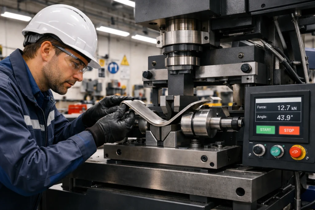
The test is deceptively simple: a specimen cut from a welded joint is bent around a precision former (mandrel) to a specified angle, typically 90°, 120°, or 180°, while the outer surface is placed in tension. Any weld defect, embrittled zone, or lack of ductility opens up on this tension face and becomes immediately visible during post-bend examination. Despite this simplicity, achieving valid, reproducible results requires meticulous attention to specimen preparation, former diameter selection, equipment calibration, and evaluation technique.
This guide provides a definitive reference for quality engineers, welding inspectors, and CWI/CSWIP-certified professionals. It covers all aspects of bend testing from first principles through to acceptance criteria, troubleshooting, advanced techniques, and the specific requirements of the major governing standards.
Understanding Bend Testing Fundamentals
What is Bend Testing?
Bend testing is a qualitative mechanical test designed to assess the ductility and soundness of metallic materials by subjecting a coupon to controlled plastic deformation. The specimen is bent around a former or mandrel to a predetermined angle while the outer (convex) surface experiences significant tensile strain that reveals any internal defects, embrittlement, or discontinuities. Unlike a tensile or impact test, the bend test does not produce quantitative strength or energy values; rather, it provides a binary pass/fail evaluation of the joint’s ability to deform plastically without opening cracks that exceed acceptance limits.
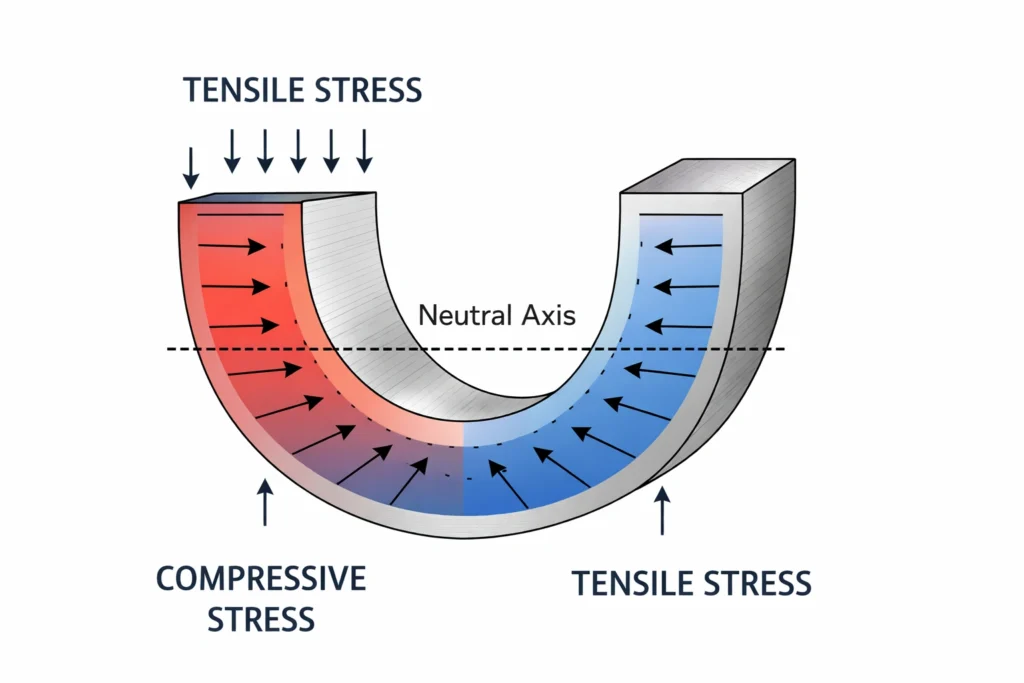
The governing principle is straightforward: when a material is bent, the convex face enters the tensile strain regime while the concave face is compressed. The tensile surface strain is approximately equal to the specimen thickness divided by twice the sum of the bend radius and half the specimen thickness — a value controlled by choosing the correct former diameter relative to thickness. Any flaws (porosity, slag, lack of fusion, hot cracks) act as stress concentrators and open up under this strain, making them clearly visible.
Types of Bend Tests
Bend testing encompasses several variations, each suited to specific applications and material conditions. Selecting the correct type is as important as the test execution itself.
1. Guided Bend Test
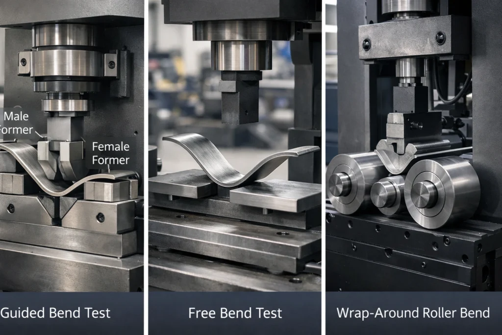
The guided bend test is the method universally specified in welding qualification standards. The specimen is wrapped around a precisely machined former of specified diameter, with a matching female die that constrains specimen movement and ensures consistent, reproducible strain. This controlled approach is mandatory in qualification procedures under ASME Section IX, ISO 9606, ISO 15614, and AWS D1.1. The former diameter is expressed as a multiple of specimen thickness — commonly 3t, 4t, or 8t — with the specific multiple determined by material properties and the applicable standard.
2. Free Bend Test
In free bend testing, the specimen is bent without constraint from a shaped former, typically between rollers or by a wedge, allowing natural deformation. Because bend radius is not precisely controlled, results are less repeatable than the guided test. Free bend testing is therefore rarely used for formal qualification but may be suitable for rapid preliminary evaluation or where only qualitative ductility assessment is needed.
3. Wrap-Around Bend Test
Similar to the guided bend test but using a roller-based mechanism similar to a pipe bender, this method progressively wraps the specimen around the former rather than pressing it simultaneously across the full span. The progressive nature distributes strain more uniformly, minimising the “peaking” phenomenon where deformation concentrates in the weaker material of a dissimilar or mismatched joint. This method is specified in some procedure qualifications involving high-strength or dissimilar metal welds, and is particularly valuable for duplex stainless steel joints or welds with significant yield strength mismatch.
| Method | Strain Control | Typical Application | Standard Reference | Peaking Risk |
|---|---|---|---|---|
| Guided Bend | Precise (fixed former dia.) | WPQ/PQR qualification | ASME IX, ISO 9606, ISO 15614, ASTM E190 | Moderate |
| Free Bend | Low (radius varies) | Preliminary material evaluation | AWS B4.0 | Low |
| Wrap-Around | Precise (progressive wrap) | Dissimilar/high-strength joints | AWS B4.0, ASTM E190 | Low |
Specimen Orientation: Face, Root, and Side Bends
The orientation of the weld within the bent specimen determines which portion of the joint is subjected to the maximum tensile strain. Choosing the correct orientation is mandated by the applicable qualification standard and determined primarily by material thickness.
Transverse Specimens
These are cut perpendicular to the welding direction and represent the most common configuration in weld qualification testing.
Face Bend
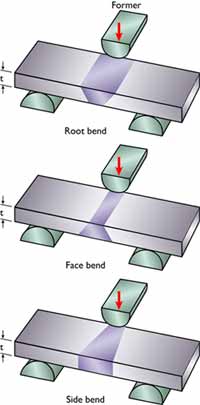
The weld face (top surface cap) is placed on the outer (tension) side of the bend. Face bends are sensitive to surface undercut, excessive reinforcement that was not removed, porosity at or near the cap, and incomplete fusion at the weld toes. They are typically required for material thicknesses up to approximately 12 mm (0.5 in).
Root Bend
The weld root is placed on the outer (tension) side of the bend, subjecting the root pass to maximum tensile strain. Root bends are the most sensitive test for incomplete root penetration, lack of root fusion, and root-region cracking. They are paired with face bends for thinner material qualification coupons.
Side Bend
A full-thickness specimen is bent with one of its cut faces placed in tension. This configuration tests the complete weld cross-section — including all weld passes, both heat-affected zones, and both fusion lines — and is particularly effective at detecting sidewall lack of fusion and inter-run defects. Side bends are mandatory for material thicknesses exceeding approximately 12 mm (0.5 in), as specified in ASME Section IX QW-163 and ISO 9606.
Longitudinal Specimens
Longitudinal specimens are cut parallel to the welding direction. They include the full weld width plus portions of both parent plates and both HAZs within a single specimen. Because the entire specimen deforms together, longitudinal bends are less effective at detecting localised defects but are valuable for dissimilar metal welds, joints with pronounced yield-strength mismatch, or when evaluating the integrity of the HAZ independently of weld metal quality.
| Orientation | Tension Face | Thickness Range | Primary Defects Revealed | ASME IX Reference |
|---|---|---|---|---|
| Face Bend | Weld cap | <12 mm (0.5 in) | Cap undercut, toe fusion, surface porosity | QW-162.1 / QW-163 |
| Root Bend | Weld root | <12 mm (0.5 in) | Root penetration, root fusion defects | QW-162.2 / QW-163 |
| Side Bend | Cut face (full thickness) | ≥12 mm (0.5 in) | Sidewall fusion, inter-run defects, HAZ cracks | QW-162.3 / QW-163 |
| Longitudinal Face | Weld cap | Any | Dissimilar/mismatched joint ductility | QW-162.4 |
| Longitudinal Root | Weld root | Any | Dissimilar/mismatched joint ductility | QW-162.4 |
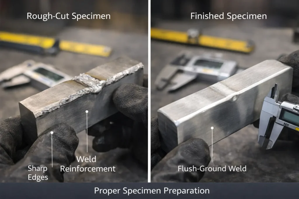
Specimen Preparation Requirements
Specimen preparation is where most bend test failures of sound welds occur. Inadequate edge preparation, residual HAZ from flame cutting, sharp corners, or improper surface finish all create stress raisers that initiate premature cracks unrelated to weld quality. Following the preparation sequence below is essential for valid results.
Step-by-Step Preparation Sequence
- Rough cutting: Cut specimens from the test piece by sawing or plasma/flame cutting. Ensure all cuts are at least 3 mm from the HAZ boundary to avoid introducing work-hardening or secondary HAZ.
- Weld reinforcement removal: Grind the face and root reinforcement flush with the parent metal surface. All grinding marks must run parallel to the length of the specimen to avoid transverse notches. Confirm with a straight-edge that the surface is truly flush — any proud weld will concentrate strain at the weld toes and produce invalid results.
- Dimensional machining: Machine the specimen to the width and thickness specified by the standard. For ASME Section IX, transverse bend specimens are typically 38 mm (1.5 in) wide for thicknesses up to 38 mm, or as specified by QW-462.1 to QW-462.3.
- Edge radiusing: Round all four longitudinal edges of the specimen to a radius of 1.5 mm to 3 mm. This is the single most important step in preventing false edge cracks. A file, belt grinder, or CNC chamfer tool can be used; verify with a radius gauge.
- Thermal cutting zone removal: If the specimen was rough-cut by flame, any orange heat tint (oxide zone) must be removed by machining or grinding. The oxygen-enriched surface layer can embrittle the material locally and cause spurious cracking.
- Final surface finish: Achieve a smooth finish (Ra <3.2 µm) on the surface that will be placed in tension. Grinding marks must be longitudinal. Inspect visually for tool marks, nicks, or inclusions before testing.
Equipment and Former (Mandrel) Selection
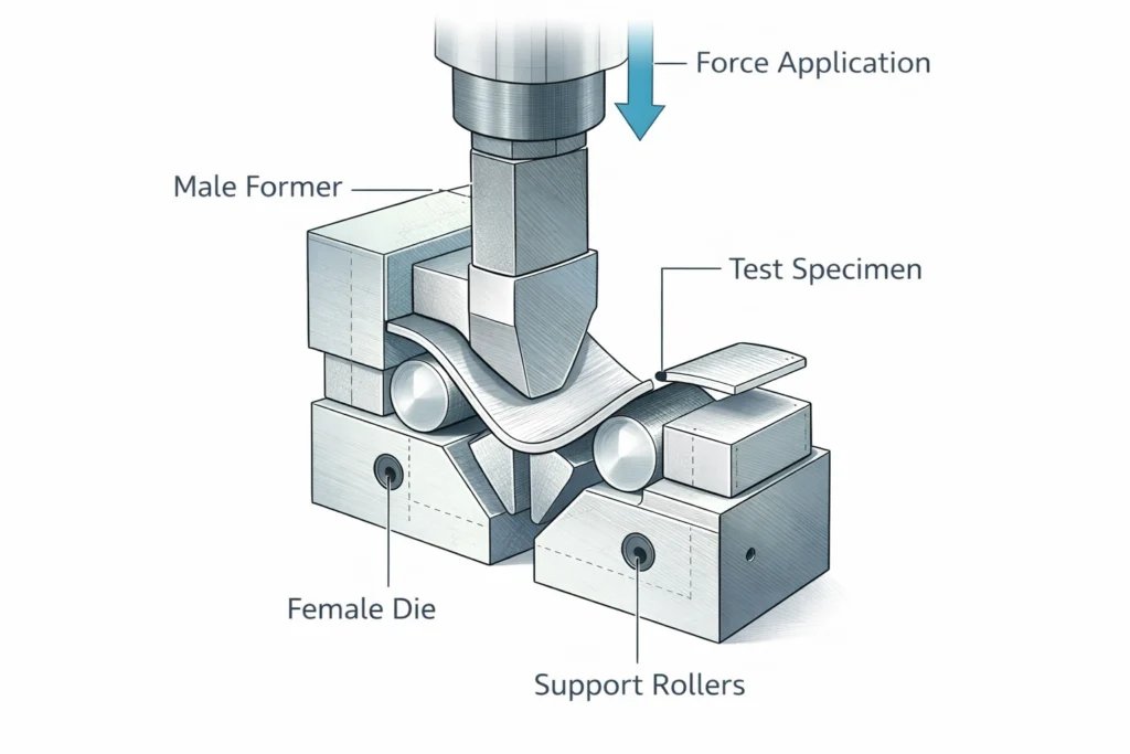
Guided Bend Test Jig Components
A standard guided bend test jig consists of a male former (plunger), a female die with a curved recess, and support rollers. Force is applied by a hydraulic press, bench vice with a screw mechanism, or dedicated hydraulic unit. The critical dimensional requirement is the former diameter, which must be traceable and verified against the applicable standard before each qualification test.
Former Diameter Requirements by Material and Standard
| Material / P-Number | ASME IX Former Dia. (QW-466) | ISO 5173 Former Dia. | Minimum Elongation |
|---|---|---|---|
| Carbon steel — P-No. 1 (mild) | 4t | 3t–4t | ≥22% |
| Low-alloy steel — P-No. 3, 4, 5 | 4t–6t | 4t–5t | ≥16% |
| P91 / Grade 91 — P-No. 5B | 8t | 8t | ≥16% |
| Austenitic stainless steel — P-No. 8 | 4t | 2t–3t | ≥35% |
| Duplex stainless — P-No. 10H | 4t | 3t–4t | ≥25% |
| Aluminium alloys — P-No. 21–26 | 6t–8t (temper-dependent) | 4t–8t | 8–22% (temper-dependent) |
| Titanium — P-No. 51–53 | 4t–6t (grade-dependent) | 4t–6t | ≥15–20% |
| Nickel alloys — P-No. 41–45 | 4t–5t | 4t | ≥30% |
Test Procedure — Step by Step
Pre-Test Verification
- Confirm specimen dimensions (width, thickness, length) against the applicable standard table (e.g., ASME IX QW-462).
- Verify former diameter against the QW-466 or ISO 5173 table for the material being qualified.
- Inspect the former and die for wear, scoring, or damage. Replace worn formers; a worn former surface introduces friction that causes specimen tearing rather than clean bending.
- Confirm the calibration status of the load-measurement device (if applicable) and angle measurement tool.
- Record ambient temperature. Testing below 0°C introduces cold-temperature effects on ductility; some specifications require elevated temperature testing.
- Photograph and mark the specimen to identify face, root, orientation, and location in the test piece for full traceability per the procedure qualification record (PQR).
Specimen Positioning and Bending
- Position the specimen on the rollers with the specified surface (face, root, or side) facing outward (away from the plunger).
- Centre the weld on the former axis. The weld centreline must align with the apex of the bend within ±3 mm.
- Apply force smoothly and continuously — no impact loading, no jarring, no reversals. For hydraulic presses, maintain a steady crosshead speed of 1–15 mm/min.
- Bend to the full angle specified (typically 180° for groove weld qualification). Do not stop partway unless the standard explicitly permits a partial bend angle for specific materials.
- If the specimen fractures completely during bending, this constitutes an immediate rejection. Record the angle at which fracture occurred.
Post-Bend Examination
Remove the bent specimen and examine the tension face under a minimum illuminance of 500 lux (natural or white artificial light). Examine at 1x (naked eye) and, where the acceptance criterion is borderline, use a 5x hand lens to measure defect dimensions accurately.
Acceptance Criteria by Standard
| Standard | Bend Angle | Max Single Defect | Max Aggregate | Edge Cracks |
|---|---|---|---|---|
| ASME Section IX QW-163 | 180° | 3 mm (1/8 in) in any direction | Not specified (each defect evaluated independently) | Excluded unless from weld defect |
| ISO 5173:2023 — Level B | 180° | 3 mm any direction | Total ≤6 mm | Excluded |
| ISO 5173:2023 — Level C | 180° | 4 mm any direction | Total ≤8 mm | Excluded |
| AWS D1.1 — 4.23 | 180° | 3 mm (1/8 in) any direction | Total ≤10 mm (3/8 in) | Excluded |
| ISO 9606-1 | 180° | 3 mm (ISO 5173 Level B applies) | Total ≤6 mm | Excluded |
| API 1104 — 5.8 | 180° | 3.2 mm (1/8 in) | Not specified | Excluded |
Common Failures and Troubleshooting
Peaking Phenomenon
Peaking occurs when deformation concentrates in the lower-strength zone of a joint — typically the austenitic stainless weld overlay on a carbon steel base, or the HAZ of a high-strength steel. The local strain at the peak can exceed the material’s ductility even though the overall joint is sound. Switch to a wrap-around bend test machine to distribute strain more uniformly, or consult the applicable standard for alternative test geometry.
Edge Cracks on Small Diameter Tubes
When testing specimens cut from pipe or tube, the curved geometry of the original material introduces additional edge stresses. Solutions include machining the specimen edges to a larger radius (up to 3 mm), selecting a wider former, or orienting the specimen so the OD face is in tension. For thin-wall pipe qualification under ASME Section IX, QW-462.2 specifies dedicated specimen dimensions.
Premature Failure from Improper Preparation
If repeated specimens from visually sound welds are failing bend tests with shallow surface cracks, suspect preparation issues before questioning the weld quality. Inspect the specimen surface under a 5x loupe before bending; any transverse grinding marks, shear-cut surfaces, or proud weld reinforcement must be corrected. See the preparation section above for the correct sequence.
Inconsistent Results Between Duplicate Specimens
Inconsistency between two face bends or two root bends from the same coupon usually indicates variation in welding conditions across the coupon width, or a difference in specimen preparation between the two specimens. Investigate heat input control, electrode change-over points, and whether the specimens were taken from the full width of the coupon or from one side only. For a structured approach to mechanical test troubleshooting, refer to the WeldFabWorld guide to mechanical testing of welds.
Governing Standards and Code References
Primary Test Method Standards
ISO 5173:2023 — Destructive Tests on Welds in Metallic Materials: Bend Tests. Defines specimen dimensions, preparation, test procedures, equipment requirements, and two acceptance levels (B and C). This is the reference standard for ISO-based qualification systems.
ASTM E190-14 (reapproved 2023) — Standard Test Method for Guided Bend Test for Ductility of Welds. Covers guided bend testing of transverse and longitudinal weld specimens, with equipment specifications and acceptance criteria. Widely used in North American practice.
AWS B4.0:2016 — Standard Methods for Mechanical Testing of Welds. The comprehensive AWS reference for all weld mechanical tests including free bend, guided bend, and wrap-around bend. Covers both PQR and WPQ application.
Qualification Standards Mandating Bend Tests
| Standard | Application | Typical Bend Requirement |
|---|---|---|
| ASME Section IX | Boiler, pressure vessel, piping PQR and WPQ | 2 face + 2 root bends (<12mm); 4 side bends (≥12mm) |
| ISO 9606-1 (steel) | Welder performance qualification | 2 face + 2 root bends (<12mm); 2 side bends (≥12mm) |
| ISO 15614-1 | Welding procedure qualification record | Per ISO 5173; side bends for t ≥ 12 mm |
| AWS D1.1 | Structural steel welding procedures and welders | 4 guided bend specimens (root/face or side per thickness) |
| API 1104 | Pipeline girth weld procedure and welder qualification | 4 root bends + 4 face bends (or 8 side bends) for procedure |
| DNV-OS-C401 | Offshore structural fabrication | Per ISO 15614; additional side bends for higher strength grades |
Bend Testing Versus Other Mechanical Tests
Bend Test vs. Tensile Test
The tensile test provides quantitative UTS, yield strength, and elongation values across the weld joint, but it does not discriminate effectively between face, root, and sidewall defects — the entire cross-section contributes to the result. Bend testing is more sensitive to localised planar defects precisely because the surface under maximum strain is clearly defined. Both tests are typically required for a full procedure qualification record.
Bend Test vs. Charpy Impact Test
The Charpy impact test (UG-84 under ASME Section VIII) quantifies absorbed energy at a specific test temperature, directly measuring notch toughness. The bend test evaluates slow-strain ductility rather than dynamic toughness. For pressure vessel and piping fabrication in sour service or low-temperature applications, both tests are required — the bend test for weld soundness, the impact test for fracture toughness assurance.
Bend Test vs. Radiographic or Ultrasonic Inspection
Volumetric NDE methods (RT, UT) detect internal defects throughout the weld volume non-destructively and are applied to production welds. Bend testing is destructive and applied only to test coupons, but it uniquely evaluates ductility — a property that RT and UT cannot measure. A weld can be radiographically clean yet fail a bend test due to hydrogen embrittlement, inadequate PWHT, or an excessively hard HAZ. Both approaches are complementary components of a robust quality system.
| Test Method | Quantitative? | Detects Ductility? | Detects Internal Defects? | Applied to Production Welds? | Typical Cost |
|---|---|---|---|---|---|
| Bend Test | Qualitative | Yes | Planar defects only | No (coupons only) | Low |
| Tensile Test | Yes | Partial (elongation) | No | No (coupons only) | Low-Moderate |
| Charpy Impact | Yes (joules) | Toughness only | No | No (coupons only) | Moderate |
| Radiography (RT) | Semi-quantitative | No | Yes (volumetric) | Yes | High |
| UT / TOFD / PAUT | Yes | No | Yes (all types) | Yes | High |
Documentation, Calibration, and Quality Assurance
Required Documentation per Test
A complete, traceable bend test record must include the following minimum data fields for audit and code compliance:
- Test date, location, and operator name/ID
- Applicable standard and edition (e.g., ASME IX 2021 Edition, QW-462.1)
- Material specification, heat/lot number, and P-Number
- Welding procedure specification (WPS) or welder ID being qualified
- Specimen dimensions, orientation (face/root/side), and location in the test piece
- Former diameter, bend angle, and bend direction
- Pre-test and post-test photographs with scale reference
- Description, size, and location of all defects observed
- Accept or reject determination with reference to the acceptance criterion applied
- Witness name, employer, and signature (where required by the relevant authority)
- Calibration reference for former dimensions and load measurement
Equipment Calibration Schedule
| Equipment Item | Calibration Interval | Acceptance Criterion |
|---|---|---|
| Former (plunger) diameter | Quarterly or every 500 specimens | ±0.5 mm of nominal or per standard tolerance |
| Female die recess dimensions | Quarterly | Within standard tolerance; no scoring or damage |
| Hydraulic load cell / pressure gauge | Annually (traceable calibration) | ±2% of full scale |
| Digital angle gauge / protractor | Annually | ±0.5° |
| Caliper / measurement tools | Annually | ±0.05 mm per ISO 9001 requirement |
| Examination lighting | Annually | ≥500 lux at specimen surface |
Recommended Reference Books
These titles are highly regarded in the welding engineering and inspection community and support deeper study of mechanical testing, weld quality, and code compliance.
Frequently Asked Questions
Why do edge cracks sometimes not count as failures in bend testing?
Can bend testing replace radiographic inspection?
How do I choose between face, root, and side bend tests?
What is the correct former diameter for ASME Section IX bend tests?
What if a material passes tensile testing but fails the bend test?
What is the acceptance criterion for a bend test per ASME Section IX?
How often should bend testing equipment be calibrated?
Can the same bend test former be used for stainless steel and carbon steel specimens?
References and Further Reading
- American Welding Society. (2016). AWS B4.0:2016 — Standard Methods for Mechanical Testing of Welds.
- ASTM International. (2023). ASTM E190-14 (reapproved 2023) — Standard Test Method for Guided Bend Test for Ductility of Welds.
- International Organization for Standardization. (2023). ISO 5173:2023 — Destructive tests on welds in metallic materials — Bend tests.
- American Society of Mechanical Engineers. (2021). ASME BPVC Section IX: Welding, Brazing, and Fusing Qualifications.
- American Petroleum Institute. (2020). API 1104: Welding of Pipelines and Related Facilities.
- American Welding Society. (2020). AWS D1.1/D1.1M: Structural Welding Code — Steel.
- Messler, R.W. (2004). Principles of Welding: Processes, Physics, Chemistry, and Metallurgy. Wiley-VCH.
- Connor, L.P. (Ed.). (1991). Welding Handbook, Volume 2: Welding Processes. American Welding Society.