How to Calculate the Strength of a Single Fillet Weld Joint
The strength of a fillet weld joint is one of the most fundamental calculations in structural and pressure equipment engineering. Fillet welds are the workhorse of fabrication — applied to T-joints, lap joints, and corner joints, they account for the vast majority of all welds made in industrial construction, shipbuilding, and structural steelwork. Despite their ubiquity, engineers frequently under-size or over-size fillet welds due to an incomplete understanding of how throat thickness, allowable shear stress, and weld length interact to determine load capacity.
This guide walks you through every step of the fillet weld strength calculation, from geometry to final load capacity. The interactive calculator below lets you solve for any combination of leg size, material UTS, and weld length instantly, with a full step-by-step formula breakdown. Whether you are using GMAW (MIG welding), SMAW (stick welding), or GTAW (TIG welding), the underlying formula is identical — the process affects quality and penetration, not the basic design calculation.
Fillet Weld Strength Calculator
What is a Fillet Weld?
A fillet weld is a weld of approximately triangular cross-section that joins two surfaces approximately at right angles to each other in a lap joint, T-joint, or corner joint. Unlike groove welds, which require joint preparation (bevelling), a fillet weld is deposited directly into the corner formed by the two members. This makes it faster and cheaper to apply, though it is less efficient in load transfer than a full-penetration groove weld of the same size.
For a detailed overview of how fillet welds relate to other joint configurations, see our guide on different types of welding joints and the comprehensive reference on nomenclature and components of butt and fillet welds.
Key Dimensions of a Fillet Weld
Leg Size
The leg size (also called the weld size or throat leg) is the length of each side of the triangular weld cross-section. For an equal-leg fillet weld — by far the most common type — both legs are equal. The leg size is the dimension specified on engineering drawings and welding symbol callouts. Per AWS A2.4 welding symbol conventions, the leg size is written to the left of the weld symbol.
Effective Throat Thickness
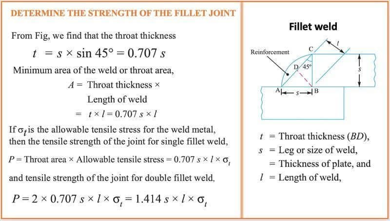
The effective throat thickness is the shortest distance from the root of the weld to the weld face (along the theoretical failure plane). For a standard 45° equal-leg fillet weld:
Where: t = effective throat (mm), w = leg size (mm)
For w = 12 mm: t = 12 × 0.7071 = 8.49 mm
The throat is the critical dimension because it represents the minimum cross-sectional area through which all shear load must be transmitted. AWS D1.1 defines the effective throat as the minimum distance from the root to the face of the weld, minus any reinforcement.
Weld Face and Root
The weld face is the exposed surface of the weld (the hypotenuse of the triangle). The weld root is the point at the bottom of the joint where the two base metal surfaces meet. The weld toe is the junction between the weld face and the base metal — this is the location most prone to fatigue cracking in cyclically loaded structures.
Factors Affecting Fillet Weld Strength
Understanding what controls fillet weld strength helps engineers make better design decisions and avoid costly over-welding or unsafe under-sizing.
| Factor | Effect on Strength | Engineering Note |
|---|---|---|
| Leg Size (w) | Proportional — doubling w roughly doubles strength | Most direct design variable; governs throat directly |
| Weld Length (L) | Linear — strength = strength/mm × L | Deduct 2×w from each end for crater losses if no run-on tabs |
| Base Metal UTS | Proportional — higher UTS raises allowable shear stress | Weld consumable must match or exceed base metal UTS |
| Welding Process | Affects penetration and quality, not the formula directly | GMAW GTAW SMAW all use the same formula |
| Joint Configuration | Double fillet ≈ 2× single fillet capacity | Double fillet also reduces distortion and improves fatigue life |
| Weld Quality / Defects | Defects (porosity, undercut, cracks) reduce effective area | Critical joints require NDT per applicable inspection standard |
| Loading Direction | Transverse loading is ~50% stronger than longitudinal | Conservative designs use the shear formula regardless of direction |
| Temperature | Elevated temperature reduces yield and tensile strength | Apply temperature de-rating factors for high-temperature service |
Fillet Weld Strength Calculation — Step by Step
The standard approach to fillet weld strength follows three steps: determine throat thickness, determine allowable shear stress, then calculate strength per unit length. Multiply by weld length for total load capacity.
Step 1 — Determine the Effective Throat Thickness
Example: w = 12 mm
t = 12 × 0.707 = 8.49 mm
Step 2 — Determine the Allowable Shear Stress
The allowable shear stress at the weld throat is taken as a fraction of the ultimate tensile strength (UTS) of the base metal. The most widely used factor in structural and pressure equipment codes is 0.3:
Example: Mild steel, UTS = 450 MPa, f = 0.30
τallow = 0.30 × 450 = 135 MPa
Step 3 — Calculate Strength per Unit Weld Length
Example:
Funit = 8.49 mm × 135 N/mm² = 1,146 N/mm
This means each millimetre of weld length can carry approximately 1,146 N (about 1.15 kN)
Step 4 — Calculate Total Load Capacity
Example: L = 200 mm weld length, single fillet
Ftotal = 1,146 × 200 = 229,200 N ≈ 229.2 kN
For a DOUBLE fillet weld of same dimensions:
Ftotal = 229,200 × 2 = 458,400 N ≈ 458.4 kN
Worked Example — Complete Calculation
A structural T-joint connection uses GMAW (MIG welding) on mild steel plate with a single fillet weld. The design requires a weld capable of carrying a 150 kN shear force. Determine the minimum leg size required for a 180 mm long weld.
L = 180 mm (effective weld length)
UTS = 450 MPa (mild steel), f = 0.30
Step 1 — Required strength per unit length Funit,req = P / L = 150,000 / 180 = 833.3 N/mm
Step 2 — Allowable shear stress τallow = 0.30 × 450 = 135 MPa
Step 3 — Required throat thickness treq = Funit,req / τallow = 833.3 / 135 = 6.17 mm
Step 4 — Required leg size wreq = treq / 0.707 = 6.17 / 0.707 = 8.73 mm
Specify: 10 mm fillet weld (round up to next standard size)
Verification: Ftotal = (10 × 0.707) × 135 × 180 = 7.07 × 135 × 180 = 171,720 N > 150,000 N ✓
Minimum Fillet Weld Size Requirements
Most structural and pressure equipment codes specify a minimum fillet weld size based on the thickness of the thicker part being joined, to ensure adequate heat input and fusion. The following table is based on AWS D1.1 guidance:
| Thicker Part Thickness (mm) | Min. Leg Size (mm) | Approx. Min. Throat (mm) | Application Note |
|---|---|---|---|
| Up to 6 | 3 | 2.1 | Light structural members, thin plate |
| 6 to 12 | 5 | 3.5 | General structural fabrication |
| 12 to 20 | 6 | 4.2 | Medium structural sections, brackets |
| 20 to 38 | 8 | 5.7 | Heavy structural, pressure vessel nozzles |
| 38 to 57 | 10 | 7.1 | Heavy plate, pressure vessel skirt attachments |
| 57 to 150 | 12 | 8.5 | Very heavy structural members |
| Over 150 | 16 | 11.3 | Offshore structures, heavy machinery bases |
Single Fillet vs. Double Fillet Weld — When to Use Each
The choice between a single and double fillet weld has implications for load capacity, distortion, accessibility, and fabrication cost. Use the comparison below to guide your design decision:
| Parameter | Single Fillet Weld | Double Fillet Weld |
|---|---|---|
| Load Capacity | Funit = t × τ | 2 × Funit = 2t × τ |
| Distortion | Tends to distort toward weld side | Balanced — reduced angular distortion |
| Fatigue Resistance | Lower — stress concentration at root | Higher — root better supported |
| Accessibility | Only one side needed | Both sides must be accessible |
| Typical Use | Non-critical, one-sided joints, secondary members | Primary structural connections, T-joints, high-load joints |
| Cost | Lower — single pass | Approximately double weld metal and time |
Important Design and Quality Considerations
Over-Sizing Welds
Excessive weld size causes more distortion, more residual stress, and higher heat input — all of which can degrade the mechanical properties of the heat-affected zone (HAZ), particularly in low-alloy steels. For materials susceptible to hydrogen cracking, such as high-strength steels or P91, pre-heat and interpass temperature requirements become more demanding as leg size increases. Refer to the P91 material welding requirements guide for high-strength alloy considerations.
Weld Quality and NDT
The calculated strength assumes a defect-free weld of the specified dimensions. In practice, welds contain minor geometric irregularities, and critical applications require non-destructive examination (NDE). Magnetic particle inspection (MPI) and dye penetrant testing (DPT) check surface-breaking defects at the weld toe and face. Ultrasonic testing (UT) checks internal defects and throat adequacy. For pressure vessels and piping, the applicable construction code specifies the NDE method and acceptance criteria. Review our article on mechanical testing methods for a broader perspective on weld qualification.
Intermittent Fillet Welds
Where the design load is modest relative to continuous weld capacity, intermittent fillet welds can reduce cost and heat input. Intermittent welds must comply with minimum stitch length and maximum spacing requirements in the applicable code. For structural steelwork under AWS D1.1, minimum stitch length is 4× the leg size (but not less than 38 mm). Maximum spacing is typically 16× the thinner plate thickness for compression members and 24× for tension members.
Fillet Weld Consumable Estimation
Once you have determined the required leg size and total weld length, you can estimate consumable requirements using the fillet weld consumable calculator. This helps with project cost estimation and material procurement.
Welding Process and Its Effect on Fillet Weld Performance
While the fundamental strength formula is process-independent, the welding process does affect fillet weld quality, penetration profile, and inspection requirements. Here is a brief overview:
| Process | Typical Application | Penetration | Position Capability |
|---|---|---|---|
| GMAW (MIG) | Shop fabrication, general structural | Medium | All positions (short-arc or pulse) |
| SMAW (Stick) | Field construction, maintenance | Medium | All positions |
| GTAW (TIG) | Thin sections, critical root passes | Low–Medium | All positions (slower) |
| SAW | Long continuous welds, heavy plate | Deep | Flat/horizontal only |
| FCAW | Structural steelwork, offshore | Medium–High | All positions (self-shielded) |
For parameter selection for GMAW and GTAW fillet welds, use the MIG welding settings calculator and TIG welding settings calculator respectively.
Recommended Reference Books
Disclosure: WeldFabWorld participates in the Amazon Associates programme (StoreID: neha0fe8-21). If you purchase through these links, we may earn a small commission at no extra cost to you. This helps support free technical content on this site.
Frequently Asked Questions
What is the throat thickness of a fillet weld?
How do you calculate the strength of a fillet weld per mm of length?
Why is the factor 0.707 used in fillet weld calculations?
What is the minimum fillet weld size for structural applications?
How does a double fillet weld compare in strength to a single fillet weld?
Does weld length affect fillet weld strength?
What welding processes are used for fillet welds?
What are common failure modes of fillet weld joints?
Conclusion
The strength of a fillet weld joint is determined by three quantities: the effective throat thickness (leg × 0.707), the allowable shear stress (typically 0.30 × UTS), and the weld length. For a 12 mm leg single fillet weld on mild steel (UTS 450 MPa), each millimetre of weld length carries approximately 1,146 N. A 200 mm long weld therefore provides around 229 kN of shear capacity — more than adequate for a wide range of structural connections.
Sound weld design goes beyond the formula, however. Minimum size requirements, maximum size limits, welding position, process selection, pre-heat, and NDT requirements all play a role in ensuring that the as-welded joint performs as designed. Use the calculator above to size your welds, cross-reference with the applicable code, and always document your design assumptions for inspection and audit purposes.
For further reading on related topics, explore joint type selection, welding symbols and drawing callouts, and fillet weld consumable estimation.