Different Types of Joints in Welding — All 5 Explained with Diagrams
Welding joints define the geometric relationship between two or more pieces of base metal before any weld is made. Understanding the five fundamental welding joint types — butt, lap, tee, corner, and edge — is the starting point for every weld procedure, every welding symbol drawing, and every fabrication specification you will ever work with. Before you can select a groove profile, calculate consumable requirements, or interpret a weld symbol on an engineering drawing, you need to be able to identify the joint type in front of you.
A critical distinction that many beginners miss: a joint type and a weld type are not the same thing. Per AWS A3.0, a joint is simply “the junction of members or the edges of members that are to be joined.” That junction can be welded using dozens of different weld groove configurations. This article covers both — explaining every joint type and the weld groove options available for each, with diagrams, comparison tables, and practical guidance drawn from AWS D1.1, AWS A2.4, and ASME Section IX.
Whether you are a student preparing for a ASME Section IX qualification, a fabricator planning a new project, or an inspector reviewing welding symbols on an isometric drawing, this guide gives you a technically complete reference you can rely on.
The Five Standard Welding Joint Types
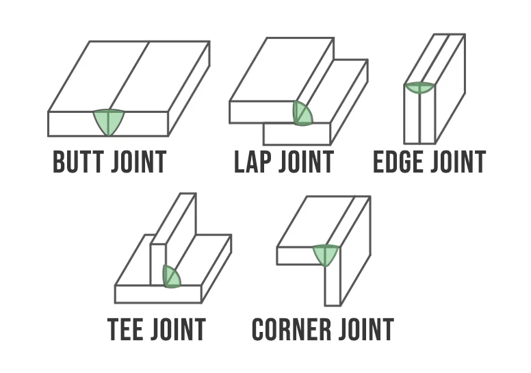
All weld joints in engineering fall into one of five categories, as recognised by AWS, ISO 9692, and ASME codes worldwide. Each represents a different way of presenting two pieces of metal for joining:
Each joint type can accept multiple weld groove configurations. Understanding this separation — joint geometry vs groove preparation — is what enables welders and engineers to communicate precisely via welding symbols and WPS documents.
1. Butt Joint Welding
A butt joint is formed when two pieces of metal are placed edge-to-edge in approximately the same plane and welded along their abutting edges. It is the most widely used joint type in pressure vessel fabrication, pipeline welding, structural steelwork, and shipbuilding because it produces the cleanest load path and is the easiest to examine by radiography or ultrasonic testing.
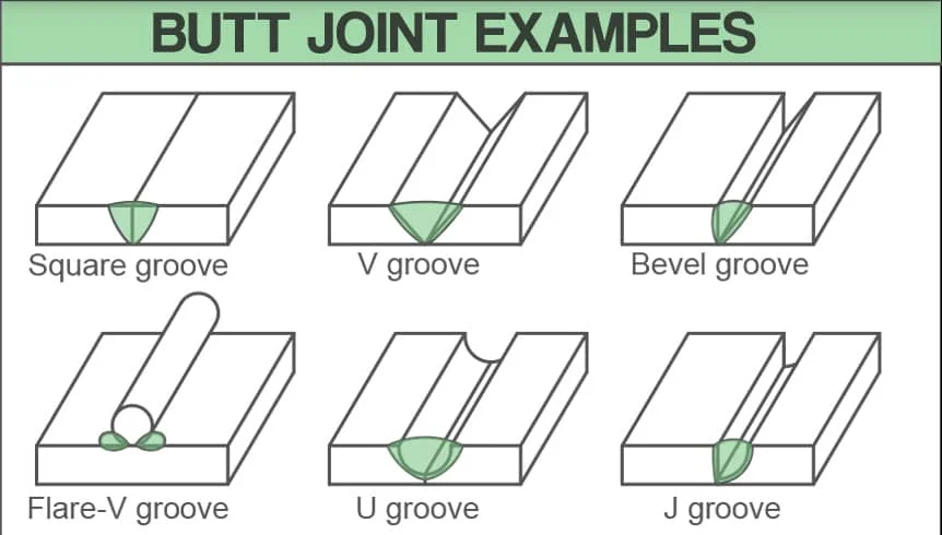
Groove Options for Butt Joints
Groove selection for a butt joint is driven by base metal thickness, access (one side or both sides), and the required level of joint penetration. The table below summarises the main groove configurations and their typical thickness ranges:
| Groove Type | Typical Thickness | Penetration | Notes |
|---|---|---|---|
| Square groove | Up to 6 mm | Full (with gap) | Minimal prep; root gap controls fusion |
| Single-V groove | 6–25 mm | Full | 60–70° included angle; most common |
| Double-V groove | >25 mm | Full | Balanced; reduces angular distortion |
| Single-bevel groove | 8–25 mm | PJP or CJP | One-side prep; access limited |
| Single-U groove | >20 mm | Full | Less weld metal than V; machined prep |
| Double-U groove | >38 mm | Full | Minimum distortion; requires machining |
| Single-J groove | 12–38 mm | PJP or CJP | One-side J cut; pipe root passes |
| Flare-V groove | Varies | PJP | Round/curved sections meeting |
CJP = Complete Joint Penetration; PJP = Partial Joint Penetration. Thickness ranges are indicative; refer to the applicable WPS and code.
Practical Engineering Notes — Butt Joints
- Keep the root face (land) consistent — typically 1–2 mm — to prevent burn-through, especially in single-sided root passes on pipe.
- Root opening (gap) controls fusion at the root. Inconsistent gaps are a primary cause of incomplete penetration defects.
- For thick plates, a double-V groove reduces overall weld volume by approximately 30–50% compared to a single-V, cutting consumable costs and minimising angular distortion.
- When one-side access only is available (e.g., inside of a pipe), use a backing strip or a GTAW root pass before switching to SMAW or FCAW fill and cap. Refer to our TIG/GTAW guide for root pass technique.
- Use the V-groove consumable calculator to estimate electrode consumption for any groove angle and base metal thickness.
2. Lap Joint Welding
A lap joint is formed when two pieces of metal are placed one on top of the other so that they overlap by a defined distance, then welded along the exposed edge or edges of the overlap zone. Lap joints are most practical when the two pieces differ in thickness — situations where achieving a true butt joint geometry would be difficult — and they are widely used in sheet metal work, structural connections, and repair welding.
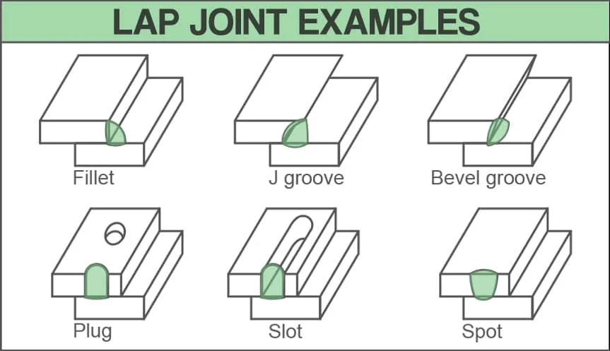
Weld Types Available for Lap Joints
| Weld Type | Common Use | Joint Strength |
|---|---|---|
| Fillet weld (single-sided) | Light structural, repair | Moderate — susceptible to peel |
| Fillet weld (double-sided) | Structural steel, platforms | Good shear and peel resistance |
| Bevel groove weld | Thick plates, high-load | High |
| J-groove weld | One-sided, thick material | Good |
| Plug weld | Sheet to frame, floor plates | Adequate in shear |
| Slot weld | Sheet panels, thin sections | Moderate |
| Spot weld (resistance) | Automotive, sheet metal | Process-dependent |
Lap Joint Design Considerations
The minimum overlap distance recommended by AWS D1.1 for structural lap joints is 5 times the thickness of the thinner member, with a minimum of 25 mm. The fillet weld leg size should be no less than the minimum for the thinner base metal thickness as given in the applicable code tables.
Use the fillet weld consumable calculator to determine electrode consumption per metre of fillet weld for any leg size. For strength calculations, refer to our article on the strength of a single fillet joint.
3. Tee Joint Welding
A tee joint is formed when one piece of metal is positioned perpendicular to another, with the end of the vertical member terminating on the face (flat surface) of the horizontal member, creating a T-shaped cross section. Tee joints are the dominant joint type in structural steel construction, machinery frames, pressure vessel nozzle attachments, and shipbuilding.
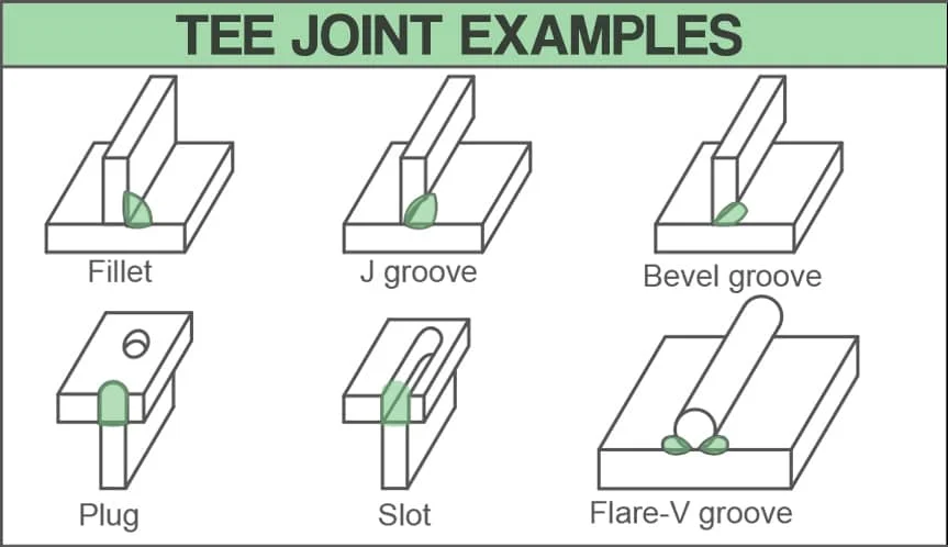
Weld Types for Tee Joints
Fillet welds are by far the most commonly used weld type on tee joints. Where high structural demand or code requirements mandate complete joint penetration (CJP), groove preparations are used:
| Weld Type | Penetration | Typical Application |
|---|---|---|
| Double fillet weld | PJP (throat dependent) | Most structural tee connections, frames, base plates |
| Single bevel groove | PJP or CJP | Heavy plates, limited access to one side |
| Double bevel groove | CJP | Full-strength connections, seismic design |
| Flare-bevel groove | PJP | Tubular/round sections meeting flat plate |
| J groove (single) | CJP possible | Thick flange-to-web connections |
| Plug / slot weld | N/A | Supplement to fillet when shear area insufficient |
Groove Preparation for Tee Joints
When the base metal is thin — generally under 10 mm for structural carbon steel — a double fillet weld alone provides adequate strength and no groove preparation is needed. When thickness exceeds roughly 20–25 mm and a full-strength joint is required, the web plate must be bevelled before fitting. A double-bevel preparation allows access from both sides and balanced heat input, reducing angular distortion.
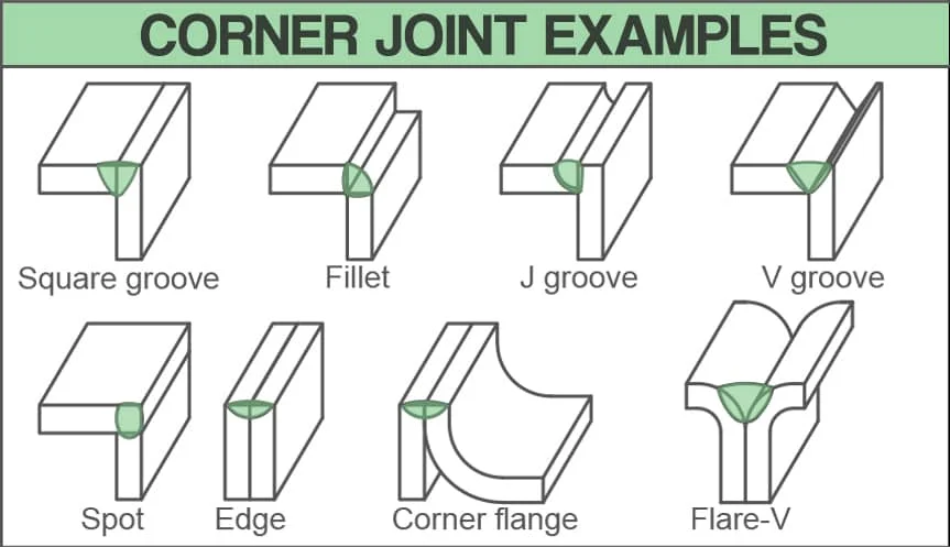
4. Corner Joint Welding
A corner joint is formed when two pieces of metal meet at their edges to form an external right-angle corner. Unlike a tee joint — where one piece terminates at the face of another — in a corner joint both pieces meet at their edges. Corner joints are extremely common in box-section fabrication, frames, enclosures, machine guards, and sheet metal work.
Open vs Closed Corner Joints
The terms open and closed describe whether there is a gap between the two pieces at the corner:
- Closed corner: One piece sits flush against the face of the edge of the other, with no gap. Typical for thin sheet metal, usually welded with a fillet on the inside face.
- Open corner: The two pieces face each other at the corner with a gap, forming a natural V channel that can be filled — typical for thicker plates and provides full fusion access.
- Half-open corner: One piece is set back slightly, creating a partial gap. Common when a clean exterior face is required.
Weld Types for Corner Joints
| Weld Type | Best For | Notes |
|---|---|---|
| Square groove (open corner) | Thin to medium plate | Simple; full penetration achievable on thin material |
| Fillet weld (inside face) | Closed corner, sheet metal | Easy access; exterior face remains clean |
| V-groove | Medium to thick plate | Good fusion; used on structural box sections |
| J-groove | Heavy fabrication | Reduced weld volume vs V |
| Flare-V groove | Tubular-to-plate corners | Rolled sections meeting at corners |
| Edge weld / corner flange | Thin sheet metal flanges | Flanged edges welded together along the edge |
| Spot weld | Sheet metal assembly | Automotive and HVAC applications |
5. Edge Joint Welding
An edge joint is formed when the edges of two parallel (or nearly parallel) pieces of metal are welded together along their adjacent edges. Both pieces lie essentially in the same plane, and the weld is made at the top edge. Edge joints are primarily used in sheet metal fabrication, where thin sections need to be joined end-to-end without overlap, and in applications where a flanged seam along the edge is functional or aesthetic.
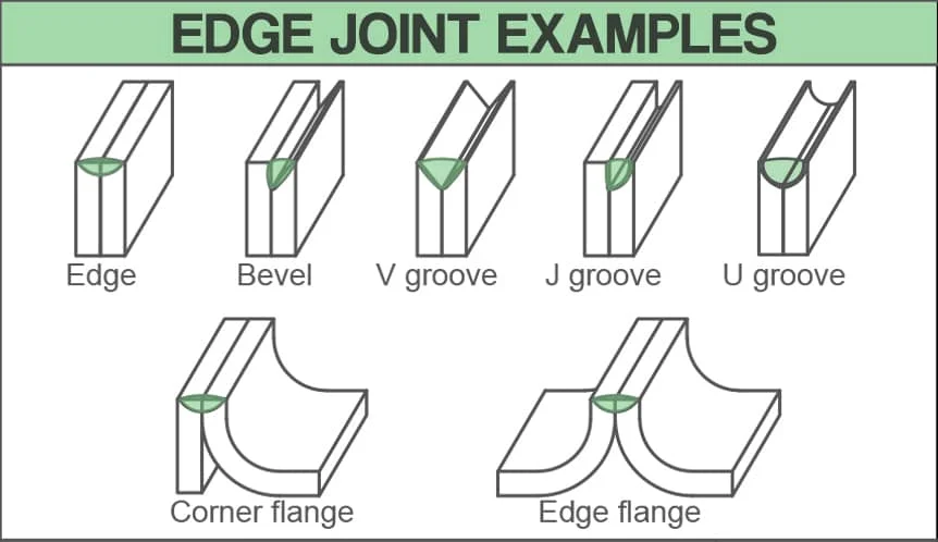
Weld Types for Edge Joints
| Weld Type | Application | Material Thickness |
|---|---|---|
| Edge weld (no prep) | Thin sheet seams, autogenous TIG | < 3 mm |
| Bevel groove | Medium sheet seams | 3–12 mm |
| V-groove | Plate seams, structural | 6–20 mm |
| J-groove | One-side access edge joints | >12 mm |
| U-groove | Thick plates, low distortion | >20 mm |
| Edge flange | Sheet metal enclosures, HVAC | Thin sheet |
| Corner flange | Flanged sheet parts | Thin to medium sheet |
The most significant challenge with edge joints is maintaining consistent fusion across thin sheet without burn-through, particularly when the two sheet edges are not perfectly aligned or the root gap is inconsistent. Autogenous (no filler) TIG welding is frequently used on stainless steel or aluminium edge joints in the food processing and pharmaceutical industries. For welding process selection, refer to our MIG/GMAW guide and TIG/GTAW guide.
How to Select the Correct Joint Type
Selecting the right joint type is determined first by the geometry of the assembly — how the pieces actually fit together in the design. The flowchart below provides a straightforward decision path from assembly geometry to joint type to typical weld groove options.
Quick Comparison — All Five Joint Types
The table below provides a side-by-side summary of all five joint types across the most important engineering criteria:
| Joint Type | Geometry | Typical Weld Types | Strength Potential | Primary Industries | RT/UT Accessible? |
|---|---|---|---|---|---|
| Butt | Edge-to-edge, same plane | Groove welds (V, U, J, bevel) | Highest (CJP = 100%) | Pressure vessels, pipelines, shipbuilding | Yes — radiography preferred |
| Lap | Overlapping, parallel | Fillet, bevel, plug, slot | Good in shear; limited in peel | Structural, sheet metal, repair | Limited — UT from face only |
| Tee | Perpendicular (T shape) | Fillet, bevel groove, J groove | High (CJP) or good (fillet) | Structures, vessels, machinery | UT required for groove welds |
| Corner | Right-angle corner meeting | Fillet, V groove, square groove, edge | Moderate to good | Box sections, enclosures, frames | Limited by geometry |
| Edge | Adjacent parallel edges | Edge weld, V groove, flange | Lower — used for sealing/light load | Sheet metal, HVAC, food processing | Difficult |
Joint Types vs Weld Types — Clearing the Confusion
One of the most common points of confusion for students and apprentices is the conflation of “joint type” and “weld type.” AWS A3.0 formally defines both, and they are distinct concepts:
| Concept | Definition (AWS A3.0) | Examples | Number of Types |
|---|---|---|---|
| Joint Type | The configuration formed by the spatial relationship of the members to be joined | Butt, lap, tee, corner, edge | 5 |
| Weld Type | The specific cross-sectional shape of the weld groove or weld deposit | Fillet, groove (V, U, J, bevel, square, flare-V, flare-bevel), plug, slot, surfacing, backing | 12+ |
The key insight: a single joint type can accept multiple weld types. For example, a tee joint can be welded with a fillet weld (most common), a single-bevel groove weld (for thicker material), a double-bevel CJP groove weld (full strength), or a plug weld (supplementary). The joint type tells you the geometry; the weld type tells you the groove or weld profile you apply to that geometry.
This distinction matters directly when reading welding symbols — the AWS A2.4 welding symbol communicates both joint type (by context of the drawing) and weld type (via the symbol on the reference line). A thorough grasp of both concepts is essential for anyone working with WPS documents, fabrication drawings, or welder qualification testing under ASME P-number and F-number systems.
Joint Types in Welding Codes and Standards
Different welding codes reference joint types in different ways. Understanding how your applicable code classifies joints helps you select the right pre-qualified joint detail and ensures your WPS is correctly structured.
AWS D1.1 — Structural Welding Code
AWS D1.1 uses the five joint types as the basis for its prequalified joint details in Annex A. Each detail specifies groove angle, root opening, root face dimension, and the processes qualified. Prequalified status means no separate qualification testing is required, provided the WPS conforms exactly to the Annex A detail. Butt and tee joint groove details dominate structural steel applications.
ASME Section IX — Welding Qualifications
ASME Section IX QW-469 defines essential variables related to groove weld geometry. Joint type is not itself an essential variable for most processes, but the groove type, base metal thickness range, and welding position are. A WPS qualified on a butt joint groove weld qualifies groove welds in butt, tee, and corner joints — making butt joint PQRs among the most versatile. See the ASME Section IX quiz to test your qualification knowledge.
ASME Section VIII Division 1 — Pressure Vessels
Section VIII Div 1 categorises welds by joint category (A, B, C, D) rather than by the five joint types, but the underlying geometry is the same. Category A and B welds are butt joints; Category C welds are corner/tee joints at flange attachments; Category D welds are corner joints at nozzle-to-shell connections. The joint efficiency factor E depends on both the joint category and the extent of radiographic examination performed.
Recommended Reference Books
These titles provide in-depth coverage of welding joint design, groove selection, and weld procedure development: