What is GMAW (MIG/MAG)? Complete Welding Guide
Gas Metal Arc Welding (GMAW) — universally known as MIG (Metal Inert Gas) or MAG (Metal Active Gas) welding — is an arc welding process in which a continuously fed consumable wire electrode and a shielding gas are delivered through a compact welding gun. An electric arc struck between the wire and the workpiece generates enough heat to melt both the electrode and the base metal, producing a fusion weld with high deposition rates and minimal post-weld cleanup. Because the process is semi-automatic or fully automatic by design, GMAW has become the dominant welding method in automotive, structural, and general fabrication industries worldwide.
Understanding GMAW in depth means understanding more than simply how to pull a trigger — it means knowing how to select the correct metal transfer mode for the material and position, how to match shielding gas composition to the metallurgical requirements of the base metal, how to dial in voltage, wire feed speed, and CTWD for a given wire diameter, and how to diagnose defects like porosity, spatter, and incomplete fusion when they appear. This guide covers all of those topics in sequence, supported by SVG process schematics, parameter reference tables, and worked calculation examples.
The governing welding procedure standard for GMAW in pressure equipment fabrication is ASME BPVC Section IX. For structural steelwork, AWS D1.1 and AWS D1.2 (aluminium) apply. The filler wire classifications used in ASME-coded work are defined in AWS/ASME SFA-5.18 (carbon steel solid wire), SFA-5.9 (stainless steel), and SFA-5.10 (aluminium), among others. See the welding consumable nomenclature guide for a full explanation of AWS classification systems.
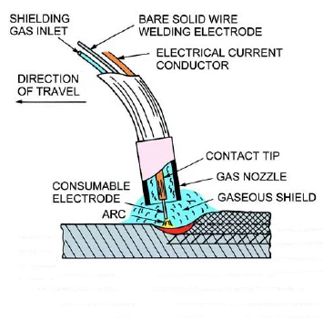
How GMAW Works — Process Schematic
GMAW operates on a constant voltage (CV) power source — sometimes called constant potential. With a CV source, the arc length is self-regulating: if the arc shortens (wire feeds faster than it melts), voltage drops, current increases, and melt-off rate rises to restore equilibrium. This self-correction makes GMAW forgiving to small variations in gun-to-work distance and is a primary reason for the process’s ease of use compared to SMAW (stick welding), which relies on the welder’s manual arc-length control.
Development and History of GMAW
The arc welding principles behind GMAW trace back to the early 19th century when Humphry Davy and Vasily Petrov independently demonstrated the electric arc. Carbon arc welding followed, succeeded by metal electrode processes pioneered by Nikolay Slavyanov and C. L. Coffin around 1890. P. O. Nobel of General Electric introduced a direct current bare-electrode wire process in 1920 that can be considered a forerunner of GMAW, but shielding gas was not used at that stage.
The modern GMAW process was developed by the Battelle Memorial Institute in 1948, using a small-diameter wire with a constant voltage power source and inert shielding gas. The cost of inert gases restricted this early process to non-ferrous materials. The critical breakthrough came in 1953 when the Soviet Union introduced CO2 as a practical shielding gas for steel welding, dramatically reducing operating costs. The short-arc (short-circuit) variation appeared in 1958, enabling welding of thin sheet metal, and rapidly became the most widely used form of GMAW. Pulsed current GMAW emerged in the 1960s–1970s and has since become the preferred mode for positional welding of aluminium and high-strength steels.
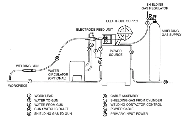
GMAW Equipment — Components and Functions
Welding Power Source
A constant voltage (CV) DC power source is standard for GMAW. Output is set by selecting open-circuit voltage; the machine then automatically adjusts current to maintain that voltage as arc length varies. Most modern GMAW machines are inverter-based, offering precise electronic control over output waveform, synergic programs that adjust voltage and inductance automatically when wire feed speed is changed, and pulsed waveform capability. DCEP (direct current electrode positive) polarity is standard for solid wire GMAW, directing the majority of arc heat into the wire tip and weld pool to maximise penetration and fusion.
Wire Feeder
The wire feeder drives the electrode wire from a spool (typically 5–15 kg) through the gun cable and liner to the contact tip at a user-set wire feed speed (WFS), measured in metres per minute (m/min) or inches per minute (in/min). Most feeders use a two-roll or four-roll drive system. Four-roll feeders provide better grip consistency on soft wires such as aluminium, reducing the wire deformation that causes birdnesting. For aluminium welding, a push-pull gun system is often used to prevent the soft wire from buckling in long torch cables.
Welding Gun
The gun assembly carries current to the wire via the contact tip, delivers shielding gas concentrically through the nozzle, and controls the wire feed through the trigger switch. Key gun components include:
- Contact tip: Usually electrolytic copper, sized to match wire diameter. The contact tip transfers current to the wire by resistive contact and must be replaced when the bore becomes worn oval, which causes erratic arcing.
- Nozzle / gas diffuser: Concentrates the shielding gas envelope around the arc. Spatter buildup inside the nozzle is the most common cause of porosity due to gas turbulence.
- Gun liner: A coiled steel or PTFE tube that guides the wire through the cable without kinking. Correct liner sizing (inner diameter 0.1–0.2 mm larger than wire) and periodic replacement are critical for consistent wire feed.
- Trigger switch: Simultaneously activates wire feed, power output, and shielding gas flow (and gas preflow/postflow timers on modern machines).
Shielding Gas Supply
Shielding gas is supplied from a high-pressure cylinder through a regulator/flowmeter. Flow rates are typically set between 15 and 25 L/min (30–50 ft³/hr) depending on nozzle diameter and draught conditions. Higher flow rates do not improve protection and can actually cause turbulence that draws in atmospheric air — a common cause of porosity in field welding. Selecting the correct gas mixture for the material is covered in detail in the shielding gas section below.
Electrode Wire
Electrode wire for GMAW is classified under AWS/ASME SFA standards by composition and mechanical properties. The most common carbon steel wire is ER70S-6, which has higher silicon and manganese content than ER70S-3 to provide deoxidation tolerance on lightly rusty or mill-scaled surfaces. Wire diameters range from 0.6 mm to 2.4 mm; the selection matrix below matches wire diameter to material thickness and transfer mode.
| Wire Diameter (mm) | Typical Material Thickness (mm) | Transfer Mode | Typical WFS Range (m/min) |
|---|---|---|---|
| 0.6 | 0.5 – 1.5 | Short-circuit | 3 – 7 |
| 0.8 | 1.0 – 3.0 | Short-circuit | 4 – 9 |
| 0.9 | 2.0 – 6.0 | Short-circuit / Pulsed | 5 – 12 |
| 1.0 | 3.0 – 10.0 | Short-circuit / Spray | 5 – 14 |
| 1.2 | 6.0 – 25.0 | Spray / Pulsed | 6 – 18 |
| 1.6 | 12.0 and above | Spray | 5 – 15 |
| 2.4 | Heavy plate (automated) | Spray / Rotating spray | 3 – 8 |
Shielding Gas Selection for GMAW
The shielding gas mix has a direct effect on arc stability, metal transfer characteristics, bead profile, penetration depth, mechanical properties, and fume generation. The wrong gas selection is one of the most common root causes of weld quality problems in fabrication shops.
| Gas / Blend | Composition | Primary Application | Transfer Mode Compatibility | Notes |
|---|---|---|---|---|
| Pure CO2 | 100% CO2 | Carbon and low-alloy steel | Short-circuit, Globular | Cheapest; deepest penetration; high spatter; cannot achieve true spray transfer |
| C25 (C10) | 75% Ar / 25% CO2 (or 90/10) | Carbon and low-alloy steel | Short-circuit, Spray, Pulsed | Most widely used for steel; good balance of penetration, bead shape, and spatter |
| 98/2 Ar-O2 | 98% Ar / 2% O2 | Stainless steel, high-alloy steels | Spray, Pulsed | O2 stabilises arc; minimises oxidation; preserves corrosion resistance |
| Ar/2%CO2 | 98% Ar / 2% CO2 | Stainless steel | Spray, Pulsed | Alternative to 98/2; slightly better wetting; check ferrite implications for delta ferrite sensitive grades |
| Pure Argon | 100% Ar | Aluminium, copper, titanium | All modes | Required for non-ferrous; spray transfer threshold is lower than for steel |
| Ar/He blends | 25–75% He / balance Ar | Aluminium, copper (heavy sections) | Spray, Pulsed | He increases heat input, travel speed, and fusion on thick sections |
| Tri-mix (Ar/He/CO2) | e.g., 90% He / 7.5% Ar / 2.5% CO2 | Austenitic stainless steel (heavy) | Spray | High heat input for thick-section stainless; used in process industry fabrication |
Metal Transfer Modes in GMAW
GMAW achieves metal transfer from the wire electrode to the weld pool through five distinct modes, each with its own current-voltage operating window, droplet formation mechanism, heat input characteristics, and suitability for different materials and positions. Selecting the correct mode is as important as selecting the correct filler metal.
Short-Circuit Transfer
The wire periodically contacts the weld pool (up to 200 times per second), short-circuiting the arc. Each contact deposits a small droplet via surface tension. Produces low heat input, minimal distortion, and excellent out-of-position capability. Best for thin sheet (below 4 mm) and root pass welding. Typical settings: 15–22 V, 50–175 A.
Globular Transfer
Large, irregular droplets larger than the wire diameter form and detach under gravity. Arc stability is poor; spatter is high. Commonly occurs with pure CO2 gas at intermediate currents. Suitable for thicker carbon steel in the flat position where spatter is tolerated. Best avoided on quality-critical work.
Spray Transfer
Above the transition current, the electromagnetic pinch force dominates and produces a fine, axially directed stream of tiny droplets. Arc is extremely stable, spatter is virtually zero, and deposition rates are high. Requires an argon-rich gas (at least 80% Ar) and is restricted to flat and horizontal positions due to the large fluid weld pool. Typical settings: 24–30 V, 200–400 A.
Pulsed Spray Transfer
An electronic waveform alternates between a high peak current (achieving spray transfer for each pulse) and a low background current (maintaining the arc). One droplet is detached per pulse. This delivers spray-quality transfer at average currents below the steady-state transition threshold, enabling all-position welding, lower heat input, and suitability for aluminium and thin stainless steel. Requires a synergic or pulsed-capable power source.
Rotating (Axial) Spray
At very high currents (above approximately 600 A for 1.6 mm wire), the arc tip rotates around the wire axis, producing an extremely wide bead with very high deposition rates (up to 15 kg/hr). Used primarily in automated hard-facing, cladding, and heavy deposition applications. Not suitable for manual welding.
GMAW Parameter Setting and Worked Example
Four primary variables control GMAW weld output: wire feed speed (WFS), arc voltage, travel speed (TS), and contact tip-to-work distance (CTWD). These are interdependent — changing one affects the others. The MIG welding settings calculator on WeldFabWorld provides automated starting parameters, but understanding the underlying relationships is essential for in-field troubleshooting.
Key Parameter Relationships
| Parameter | Effect of Increase | Effect of Decrease | Typical Range (1.2 mm ER70S-6) |
|---|---|---|---|
| Wire Feed Speed (WFS) | Current increases, deposition rate increases, penetration increases | Current decreases, risk of burn-back to tip | 6 – 18 m/min |
| Arc Voltage | Arc length increases, bead width increases, risk of undercut and porosity | Arc length decreases, bead narrows, risk of cold lap and stub-out | 24 – 32 V (spray) |
| Travel Speed | Bead gets thinner and narrower, less heat input per mm | Bead gets wider and taller, more heat input, risk of burn-through on thin plate | 300 – 600 mm/min |
| CTWD (Stick-out) | Resistive preheating increases, effective current drops, deposition rate rises slightly | Tip overheating, spatter inside nozzle | 19 – 25 mm (spray) |
Worked Example: Heat Input Calculation
For a ASME Section IX procedure qualification, heat input must be recorded on the PQR. The standard formula for arc energy per unit length is:
GMAW Operation — Technique and Gun Positioning
GMAW is classified as a semi-automatic process: the wire feed and current are automatically maintained, but the welder controls gun position, travel angle, travel speed, and weaving pattern. The level of skill required is substantially lower than for GTAW (TIG welding), but producing consistently high-quality welds still demands disciplined technique.
Travel and Work Angles
| Joint Type | Work Angle | Travel Angle (Forehand / Backhand) | Notes |
|---|---|---|---|
| Flat butt joint | 90° to workpiece | 5–15° forehand (push) | Push technique gives flatter bead, better gas coverage |
| Flat fillet joint | 45° to the joint | 5–15° forehand | Ensure equal fusion on both plates |
| Horizontal fillet | 45° or slight bias toward vertical plate | 5–15° forehand | Slight upward angle prevents undercut on vertical plate |
| Vertical up | 90° | 5–10° forehand (up direction) | Weaving or stepped technique; use short-circuit or pulsed mode |
| Overhead | 90° | 5–10° forehand | Reduce current/WFS by 10–15%; shorter CTWD |
Common GMAW Defects — Causes and Remedies
| Defect | Primary Causes | Remedies |
|---|---|---|
| Porosity | Contaminated base metal (oil, rust, moisture, paint), blocked nozzle, draught disrupting gas shield, insufficient flow rate, wrong gas | Clean base metal, clear nozzle spatter, increase flow rate (15–25 L/min), provide wind protection, check gas hose connections for leaks |
| Excessive Spatter | Voltage too high, WFS too high relative to voltage, poor gas mixture, incorrect mode (globular), contaminated wire | Reduce voltage or increase slightly to optimise arc length, switch to argon-rich gas, use pulsed mode, check wire cleanliness and storage |
| Incomplete Fusion (Cold Lap) | Travel speed too fast, voltage too low, wrong gun angle, insufficient preheat on thick sections | Reduce travel speed, increase voltage slightly, correct gun angle to direct arc at joint faces, apply preheat for sections above 12 mm |
| Undercut | Voltage too high, travel speed too fast, incorrect work angle on fillet joints | Reduce voltage, reduce travel speed, adjust work angle to ensure equal heat distribution between joint members |
| Burn-through | Heat input too high for thin material, slow travel speed, WFS too high | Reduce WFS and voltage, increase travel speed, use short-circuit or pulsed mode, consider backing bar for root passes |
| Wire Birdnesting | Drive roll pressure too high (deforming wire), kinked liner, obstruction in liner or contact tip | Reduce drive roll tension, replace liner, clear or replace blocked contact tip, for aluminium use push-pull gun |
GMAW Applications in Industry
GMAW’s combination of speed, versatility, and ease of automation makes it the process of choice across a wide range of industries. Key applications include:
- Automotive manufacturing: Robotic GMAW dominates body-in-white welding for carbon steel and high-strength steel (HSS) structural components. Pulsed GMAW is used for aluminium body panels.
- Structural steelwork: Semi-automatic GMAW with C25 gas and 1.2 mm wire is standard for fabricating beams, columns, and connections in construction. See the welding joint types guide for configuration reference.
- Pressure vessel and piping fabrication: GMAW fills and cap passes on carbon and low-alloy steel piping are common, qualified to ASME Section IX. The V-groove consumable calculator and fillet weld consumable calculator can help estimate wire consumption for budgeting.
- Shipbuilding: High-deposition GMAW in the flat position, often with tandem wire systems, for plate and stiffener welding.
- Maintenance and repair: The portability of GMAW equipment and rapid arc starting makes it a practical choice for field repair of plant and equipment across oil and gas, mining, and heavy industry.
- Aluminium fabrication: Pulsed GMAW with push-pull torches and pure argon is widely used for marine, aerospace, and architectural aluminium structures.
Safety Considerations in GMAW
GMAW produces intense UV and IR radiation, electrical hazards, fumes and gases, spatter, and fire risk. Appropriate controls must be in place on every worksite:
- Personal Protective Equipment: Auto-darkening or fixed shade 10–12 welding helmet; leather welding jacket, gloves, and boots; UV-rated safety glasses for bystanders.
- Fume extraction: Local exhaust ventilation (LEV) at the source is mandatory for enclosed spaces and when welding galvanised, coated, or stainless steel. Hexavalent chromium fumes from stainless steel GMAW are a known carcinogen and require respirator use when LEV is insufficient.
- Electrical safety: Never touch the contact tip or live parts. Inspect cables and gun bodies for damage before use. Ensure the workpiece is correctly earthed through the work lead — a poor work lead connection causes arc instability and can cause dangerous voltage on the workpiece frame.
- Fire prevention: Remove combustibles from the welding zone (3 m minimum) and have a fire extinguisher rated for electrical fires readily available. Post a fire watch for 30–60 minutes after welding in areas with combustible materials in adjacent spaces.
- Shielding gas asphyxiation: High-flow inert gas (argon, CO2) displaces oxygen. Never use GMAW in confined spaces without forced ventilation and atmospheric monitoring for oxygen depletion.