Ferrite Testing — Why It Matters in Stainless Steel Welding
Ferrite testing, also known as a ferritescope test, is a fast, non-destructive inspection technique used to measure delta ferrite levels in austenitic and duplex stainless steel weld deposits. Maintaining the correct ferrite content is one of the most important quality assurance activities in stainless steel fabrication: too little ferrite in an austenitic weld creates a hot-cracking risk during solidification, while too much ferrite in a duplex weld undermines toughness, corrosion resistance, and long-term microstructural stability. This guide covers the metallurgy behind ferrite, the instruments and methods used to measure it, the WRC-1992 constitution diagram, acceptance criteria by steel type, the FN-to-percent conversion formulas, and the code requirements that make ferrite testing mandatory in pressure equipment and structural fabrication.
Whether you are a welding engineer specifying consumables, a QC inspector performing production tests, or a student preparing for an AWS CWI or CSWIP examination, the technical detail here will give you a thorough and practical understanding of ferrite testing — why it is done, how it is done, and how to interpret the results correctly.
What is Delta Ferrite?
In stainless steels, the term delta ferrite refers to the body-centred cubic (BCC) iron phase that forms at high temperatures during solidification and is retained — partially or fully — in the room-temperature microstructure. It is distinct from the ferrite that forms by solid-state transformation at lower temperatures in plain carbon and low-alloy steels. Delta ferrite is one of the two primary microstructural phases in stainless steels, the other being austenite (face-centred cubic, FCC). Their relative proportions are controlled by chemistry — specifically the balance between ferrite-stabilising elements (chromium, molybdenum, silicon, niobium, titanium) and austenite-stabilising elements (nickel, manganese, nitrogen, carbon, copper).
Delta ferrite is ferromagnetic, whereas austenite is paramagnetic (effectively non-magnetic). This magnetic contrast is the physical basis for the non-destructive ferritescope measurement. The percentage of delta ferrite present in a stainless steel weld directly affects hardness, toughness, ductility, weldability, and corrosion resistance. Understanding the importance of delta ferrite in stainless steel welds is foundational to specifying and interpreting ferrite tests correctly.
Ferrite-Stabilising vs. Austenite-Stabilising Elements
The WRC-1992 diagram predicts ferrite content by combining the effects of these competing elements into two composite parameters:
Why Ferrite Control Matters
The consequences of incorrect ferrite content in stainless steel welds are severe enough that ferrite testing is specified on virtually all critical stainless fabrication projects. The two primary concerns run in opposite directions:
Too Little Ferrite: Hot Cracking Risk
Fully austenitic weld deposits are susceptible to solidification hot cracking (also called centreline cracking or liquation cracking). During solidification, low-melting-point compounds of sulphur, phosphorus, and silicon segregate to the grain boundaries and interdendritic regions. If the weld solidifies as 100% austenite, these films remain continuous and can rupture under the thermal stresses of solidification. The presence of even a small amount of delta ferrite (FN 3 to FN 4 minimum) disrupts the continuous austenite grain boundary network, effectively interrupting these liquid films and dramatically reducing hot-cracking susceptibility.
This is why most austenitic stainless consumable specifications (AWS A5.4 for SMAW electrodes, AWS A5.9 for bare wire) carry minimum reported FN values — typically FN 3 to FN 8 depending on the grade. The risk of hot cracking also increases with higher heat input, wider root gaps, and heavily diluted single-pass welds. See our companion guide on stainless steel weld decay for how microstructural changes in the HAZ interact with corrosion behaviour.
Too Much Ferrite: Sigma-Phase Embrittlement and Corrosion Loss
Above FN 10 to FN 14 in austenitic weld deposits, the following degradation mechanisms become concerns:
- Sigma-phase precipitation: Delta ferrite transforms to the brittle intermetallic sigma phase (σ) when held in the temperature range 600°C to 900°C. Sigma phase causes severe embrittlement and loss of toughness. This is a major concern for elevated-temperature service (e.g., pressure vessels operating above 450°C) and for components that undergo post-weld heat treatment.
- Reduced toughness: High ferrite content reduces impact toughness, particularly at low temperatures. Cryogenic applications (e.g., LNG tanks, cold boxes) typically specify maximum FN 5 to FN 8.
- Reduced corrosion resistance: In austenitic grades used for corrosive service (chemical plant, food processing, pharmaceutical), high ferrite can create galvanic cells and preferential corrosion paths. High ferrite also increases susceptibility to stress corrosion cracking in chloride environments.
Ferrite Requirements by Stainless Steel Type
Austenitic Stainless Steels (e.g., 304/304L, 316/316L, 321, 347)
These grades contain low ferrite in the base metal (<1% in the annealed condition). The weld deposit must be formulated to contain a controlled amount of retained delta ferrite. The standard acceptance range is FN 4 to FN 10 for most general-service applications. Corrosion-sensitive applications may tighten this to FN 4 to FN 8. Cryogenic service may limit the maximum to FN 5. The ferrite is progressively reduced with each subsequent weld pass as the heat of welding partially transforms it to austenite.
Duplex Stainless Steels (e.g., 2205 / S31803, 2507 / S32750)
Duplex stainless steels are designed to contain roughly equal proportions of austenite and ferrite in the base metal (approximately 45–55% ferrite in the solution-annealed condition). The welding of duplex stainless steels requires careful control of ferrite in the weld deposit: the target range is 30–65% ferrite, with most specifications aiming for 35–55%. The main challenge in duplex welding is that fast cooling rates (high ferrite) and high heat input (excessive austenite) both degrade performance. Interpass temperature must be controlled (typically 150°C maximum) and heat input kept within the qualified range.
Ferritic Stainless Steels (e.g., 409, 430, 444)
Ferritic grades contain up to 100% ferrite in the annealed condition. They are weldable but susceptible to grain coarsening in the HAZ because ferrite does not undergo the austenite-to-ferrite phase transformation on cooling that would refine the grain structure. Ferrite testing of ferritic stainless welds is less common than for austenitic and duplex grades, but minimum ferrite content of 85% is cited in some specifications to confirm the correct microstructure is present.
Martensitic Stainless Steels (e.g., 410, 420, 431)
Martensitic grades transform to martensite on cooling from the austenite range. In the fully annealed condition they contain 75–95% ferrite. For welding applications, preheat and controlled interpass temperature are required to manage the martensitic transformation and prevent hydrogen-induced cracking. The acceptable ferrite range for corrosion resistance is typically 75–90% in the annealed base metal. Welding of martensitic stainless steels is discussed further in the context of corrosion mechanisms relevant to these grades.
| Stainless Steel Family | Base Metal Ferrite (%) | Weld Deposit Target | Key Concern |
|---|---|---|---|
| Austenitic (304, 316, 321, 347) | <1% (annealed) | FN 4–10 | Hot cracking (too low); sigma phase / corrosion (too high) |
| Duplex 22% Cr (2205 / S31803) | 40–60% | 30–65% (target 35–55%) | Hot cracking (too low); toughness / corrosion loss (too high) |
| Super-Duplex 25% Cr (2507 / S32750) | 40–55% | 30–65% (target 35–50%) | Same as duplex; intermetallic risk higher due to Mo/W content |
| Ferritic (409, 430, 444) | Up to 100% | Min 85% | HAZ grain coarsening; loss of ductility if martensitic phase forms |
| Martensitic (410, 420) | 75–95% (annealed) | 75–90% (annealed) | Hydrogen cracking; preheat essential; PWHT required |
Ferrite Testing Methods
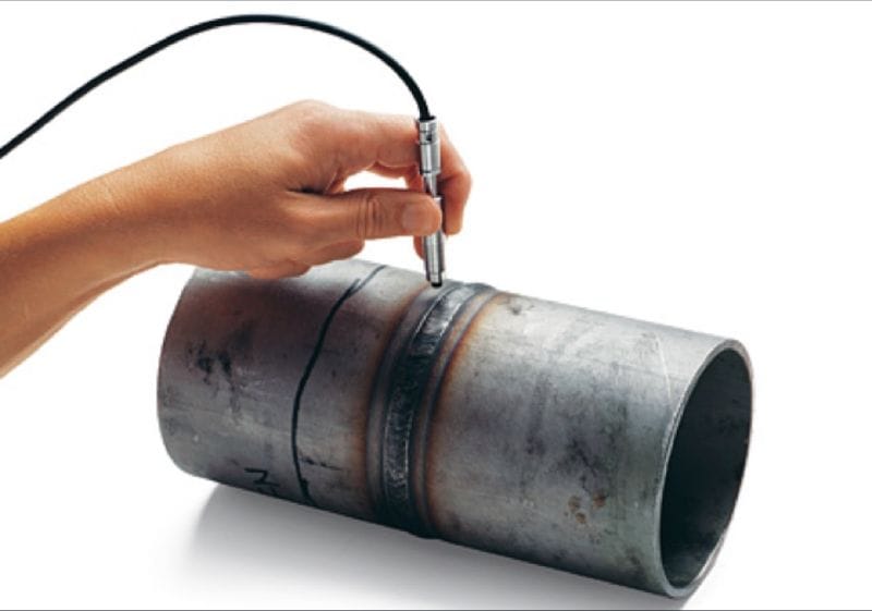
1. Ferritescope (Magnetic Induction) — Non-Destructive
The ferritescope is the standard instrument for production ferrite testing. It operates on the magnetic induction (permeability) principle: the probe generates an alternating magnetic field, and the ferrite phase — being magnetically permeable — alters the inductance in proportion to its volume fraction. The instrument converts this change to a Ferrite Number (FN) reading, calibrated against reference standards traceable to the IIW (International Institute of Welding) primary standards.
Key operating requirements for reliable ferritescope readings:
- Probe must be held perpendicular to the surface (angle deviations above 10° significantly affect readings)
- Minimum specimen thickness: typically 3 mm (readings become unreliable on thinner material due to back-wall effects)
- Minimum distance from edges and fusion lines: typically 5–6 mm to avoid edge effects
- Surface must be clean and free of mill scale, heavy oxides, paint, or coatings that could affect the magnetic field
- Calibration must be performed with reference standards at the working temperature (not assumed from earlier calibration)
- Take a minimum of 3 readings per location and average the results; discard outliers if the spread exceeds 10%
2. Metallographic Point Counting — Destructive (Reference Method)
Metallographic point counting involves preparing a cross-section through the weld, etching to reveal the phase contrast between ferrite and austenite, and counting the phases under a calibrated optical microscope using a grid overlay. The ASTM E562 standard describes the procedure. This method is accurate but time-consuming, requires metallographic preparation and expert interpretation, and is therefore used as a reference method — for procedure qualification, arbitration of disputed ferritescope readings, and scientific investigation — rather than routine production testing.
3. Image Analysis — Semi-Destructive
Digital image analysis software applied to metallographic micrographs can quantify phase fractions with good repeatability. It requires the same specimen preparation as point counting but offers faster analysis and reduced operator subjectivity. It is increasingly used in materials research and procedure qualification testing.
Comparison of Methods
| Method | Destructive? | Speed | Accuracy | Portability | Typical Use |
|---|---|---|---|---|---|
| Ferritescope (magnetic induction) | No | Fast (seconds per reading) | Good (±1–2 FN typical) | Fully portable | Production QC, site inspection |
| Metallographic point counting | Yes | Slow (hours) | High | Lab only | Procedure qualification, arbitration |
| Image analysis | Yes | Moderate | High | Lab only | Research, procedure qualification |
The WRC-1992 Constitution Diagram
The WRC-1992 diagram (Kotecki and Siewert, 1992) is the current industry standard for predicting the Ferrite Number and solidification mode of stainless steel weld deposits from their chemical composition. It replaced the earlier Schaeffler (1949) and DeLong (1974) diagrams, which gave less accurate predictions for welds with elevated nitrogen content — a common feature of modern austenitic and duplex grades.
To use the WRC-1992 diagram, you calculate Creq and Nieq from the weld metal composition (accounting for dilution from the base metal), then plot the resulting point on the diagram and read off the predicted FN from the contour lines. The diagram also shows the primary solidification mode: FA (ferrite primary, austenite secondary) or AF (austenite primary) — a distinction critical to hot-cracking prediction. FA-mode solidification is strongly preferred in austenitic welds because it retains residual delta ferrite.
Ferrite Acceptance Criteria
Acceptance criteria for ferrite content depend on the grade, the application, and the governing project specification. The following represents standard industry practice:
| Application / Grade | Minimum FN | Maximum FN / % | Notes |
|---|---|---|---|
| Austenitic SS — general service (304, 316, 321, 347) | FN 4 | FN 10 | AWS A5.4 / A5.9 reported minimum; ASME accepted range |
| Austenitic SS — cryogenic service (<-196°C) | FN 3 | FN 5 | Low max to preserve impact toughness |
| Austenitic SS — high-temperature service (>450°C) | FN 4 | FN 8 | Low max to limit sigma-phase transformation risk |
| Duplex SS 22% Cr (2205 / S31803) | 30% | 65% | Typically 35–55% targeted; ASTM A923 / NORSOK M-601 |
| Super-duplex SS 25% Cr (2507 / S32750) | 30% | 65% | Typically 35–50% targeted; intermetallic risk increases above 60% |
| Ferritic SS (409, 430) | 85% | 100% | Confirms correct microstructure post-weld |
FN to Ferrite Percentage Conversion
Ferrite Number (FN) and ferrite volume percentage (%) are related but not identical quantities. At low values (up to approximately FN 10), they are nearly numerically equal. Above FN 10, the relationship becomes non-linear. The following conversion equations are commonly cited in industry for duplex stainless grades:
Code and Standard Requirements for Ferrite Testing
ASME Section IX
ASME Section IX does not directly mandate ferrite testing but recognises it as an essential variable for certain P-Number 8 (austenitic stainless) and P-Number 10H (duplex stainless) procedure qualifications when the application material specification or client specification requires it. Changes in filler metal classification that alter the minimum reported FN require requalification of the WPS. For ASME pressure equipment work, also refer to the requirements in the applicable Division (VIII Div.1 or Div.2) and the ASME Code Case or material specification. Test your knowledge with our ASME Section IX practice quiz.
AWS A5.4 and A5.9 — Consumable Reporting
AWS A5.4 (SMAW electrodes for stainless) and AWS A5.9 (bare wire for stainless) require that the diffusible ferrite content of the weld deposit be reported as a minimum FN value determined by the WRC-1992 diagram from the deposit chemical analysis. This reported minimum FN becomes a critical quality parameter when ordering consumables for ferrite-controlled applications. For information on how to read and apply these standards, see our guide to welding consumable nomenclature.
AWS D1.6 — Structural Welding of Stainless Steel
AWS D1.6 requires that the Ferrite Number of the weld filler metal be reported and that it fall within the range specified for the service condition. Ferrite testing of production welds is required when specified in the contract documents. The FN must be reported on the procedure qualification record (PQR).
NORSOK M-601 and ISO 17781
For offshore oil and gas applications, NORSOK M-601 and ISO 17781 (Testing and inspection of CRA weld overlays and welding procedures for duplex and super-duplex stainless steels) specify ferrite testing requirements in detail, including minimum reading frequency (typically every 300 mm of weld or every layer for procedure qualification), number of readings per location, reporting format, and acceptance criteria. These standards apply to all duplex and super-duplex weld procedures used in offshore topsides fabrication. Understanding sour service requirements for stainless steels is directly relevant to these applications.
Production Testing Frequency
A typical production inspection and test plan (ITP) for critical stainless fabrication might specify:
- One ferrite test location per 300 mm of completed weld (linear welds)
- A minimum of three readings per test location, averaged
- Testing to be performed by qualified personnel using a calibrated, certificated ferritescope with current calibration certificate traceable to IIW reference standards
- Results recorded on a ferrite test report form, with weld identification, joint number, pass/location, instrument serial number, calibration date, and FN values
Free Resources and Downloads
The following training resources are available as free downloads to support your study of welding inspection and quality control topics:
Weld Consumable Excel Calculator
Download ExcelWeld Consumable Calculation PPT — Training
Download PPTWelding Symbols PPT — Training
Download PPTWelding Joint & Symbols Guide PDF (96 pages)
Download PDFRecommended Books on Stainless Steel Welding and Ferrite Metallurgy
Welding Metallurgy of Stainless Steels
A focused reference on the metallurgy behind austenitic, duplex, and ferritic stainless welds, covering ferrite, phase diagrams, HAZ behaviour, and corrosion.
View on AmazonDuplex Stainless Steels (Alvarez-Armas & Degallaix)
Comprehensive coverage of duplex stainless metallurgy, welding, ferrite control, corrosion testing, and industrial applications.
View on AmazonWelding Metallurgy (Sindo Kou)
The leading university and industry text on weld microstructure, solidification, HAZ behaviour, and cracking phenomena including hot cracking in stainless steels.
View on AmazonAWS Welding Handbook Vol. 4 — Materials & Applications
The AWS reference covering stainless steel welding, consumable selection, ferrite prediction, and acceptance criteria for all major stainless families.
View on AmazonDisclosure: WeldFabWorld participates in the Amazon Associates programme (StoreID: neha0fe8-21). If you purchase through these links, we may earn a small commission at no extra cost to you. This helps support free technical content on this site.