How to Read a Vernier Scale — Step-by-Step Guide with Worked Examples
Knowing how to read a Vernier scale correctly is a fundamental skill for any inspector, machinist, or fabricator. The Vernier caliper is among the most widely used precision instruments on the shop floor, capable of measuring outside diameters, inside diameters, depth, and step height to a resolution of 0.02 mm — or better. Unlike digital calipers, the Vernier scale demands deliberate, practised reading technique; a single misread line costs you accuracy and can result in out-of-tolerance work, rejected components, or costly rework.
This guide covers every aspect of Vernier scale reading: the physics behind how the scale works, step-by-step reading procedure, the derivation of least count, worked numerical examples with full calculations, measurement applications in fabrication and inspection, a complete breakdown of common errors and how to avoid them, and a comparison of 10-division, 20-division, and 50-division Vernier scales. Whether you are preparing for a welding inspection certification, learning metrology for the first time, or refreshing your workshop technique, this article gives you everything you need.
What Is a Vernier Scale?
A Vernier scale is an auxiliary sliding scale, invented by Pierre Vernier in 1631, that increases the resolution of any linear or angular measuring instrument beyond what the main scale graduation alone can provide. It works by exploiting the small difference between the length of one main scale division and one Vernier scale division — a difference that is precisely equal to the instrument’s least count.
In a Vernier caliper, the main scale is engraved on the fixed beam while the Vernier scale is engraved on the sliding jaw assembly. The Vernier scale has slightly compressed divisions compared to the main scale, and the specific Vernier division that aligns flush with any main scale line directly encodes the fractional part of your measurement. This elegant optical trick requires no electronics, no batteries, and no calibration beyond a simple zero-error check.
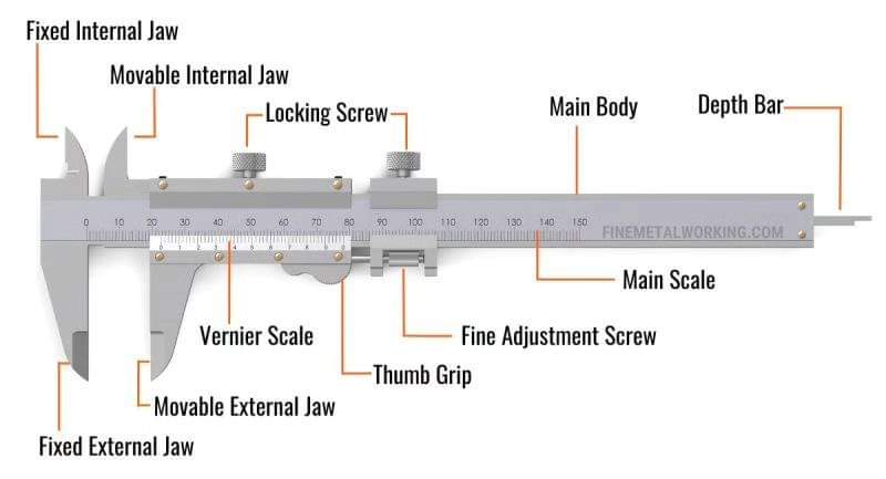
Components of a Vernier Caliper
Main Scale (Fixed Beam)
The main scale is engraved on the fixed jaw side of the beam. Divisions are typically 1 mm apart on metric instruments. Every 10 mm is labelled for quick reading. The main scale provides the whole-number and first decimal (coarse) part of the measurement.
Vernier Scale (Sliding Jaw)
The Vernier scale is engraved on the sliding jaw assembly. It contains a defined number of divisions (10, 20, or 50) that span a length slightly shorter than the equivalent number of main scale divisions. This compression is what produces the alignment effect used for reading.
Jaws
Lower (external) jaws are the large pointed jaws that close against the outside of an object to measure outer dimensions. Upper (internal) jaws are the smaller knife-edge jaws above the beam, used to measure inner diameters and groove widths by inserting them into the opening and expanding outward.
Depth Rod
A flat, narrow rod that protrudes from the end of the beam as the sliding jaw moves. It is inserted into a hole or slot to measure depth directly from the beam’s reference face.
Locking Screw (Clamping Screw)
A thumbscrew that locks the sliding jaw in position once the measurement is taken. This is essential when you need to remove the caliper from the workpiece before reading the scale, or when measuring a dimension that cannot be read in situ.
Understanding Least Count — The Physics Behind the Vernier
The least count (LC) is the smallest measurement increment the instrument can reliably indicate. For a Vernier caliper it is derived from the mismatch between main scale divisions and Vernier scale divisions.
LC = 1 MSD − 1 VSD
where MSD = one main scale division, VSD = one Vernier scale division
For a 50-Division Vernier Scale
49 main scale divisions span 50 Vernier scale divisions
1 VSD = 49/50 mm = 0.98 mm
LC = 1 mm − 0.98 mm = 0.02 mm
For a 20-Division Vernier Scale
19 main scale divisions span 20 Vernier scale divisions
1 VSD = 19/20 mm = 0.95 mm
LC = 1 mm − 0.95 mm = 0.05 mm
For a 10-Division Vernier Scale
9 main scale divisions span 10 Vernier scale divisions
1 VSD = 9/10 mm = 0.90 mm
LC = 1 mm − 0.90 mm = 0.10 mm
The physics is elegant: each successive Vernier division that passes the zero position advances the fractional part of the measurement by exactly one LC. When the nth Vernier division aligns with any main scale line, the fractional reading is n × LC. Only one Vernier line aligns at any given jaw position, making the reading unambiguous.
| Vernier Divisions | MSD | VSD | Least Count | Typical Use |
|---|---|---|---|---|
| 10 | 1 mm | 0.90 mm | 0.10 mm | General workshop, teaching |
| 20 | 1 mm | 0.95 mm | 0.05 mm | General engineering inspection |
| 50 | 1 mm | 0.98 mm | 0.02 mm | Precision fabrication, QC inspection |
| 25 (inch) | 0.025 inch | 0.024 inch | 0.001 inch | Imperial precision measurement |
How to Read a Vernier Scale — Step-by-Step
Reading a Vernier caliper correctly follows a consistent five-step procedure regardless of the instrument’s size or resolution.
Worked Examples
Example 1 — Metric (50-Division Vernier, LC = 0.02 mm)
A 50-division Vernier caliper is used to measure the outside diameter of a pipe. The observations are: the Vernier zero falls just past the 27 mm mark on the main scale; the 36th Vernier division aligns with a main scale line.
Vernier type: 50-division | Least count: 0.02 mm
Step 1 — Main Scale Reading (MSR)
MSR = 27 mm ← last graduation to the left of Vernier zero
Step 2 — Vernier Scale Reading (VSR)
VSR = 36 × 0.02 mm = 0.72 mm
Step 3 — Total Reading
Total = MSR + VSR = 27 mm + 0.72 mm
Final Answer = 27.72 mm
Example 2 — With Zero Error Correction
Before measurement, the caliper’s jaws are closed and the zero is checked. The Vernier zero is found to be 2 divisions past the main scale zero — a positive zero error of 2 × 0.02 = +0.04 mm. The measurement gives MSR = 15 mm, Vernier division 21 aligned.
Uncorrected Reading
= 15 mm + (21 × 0.02) mm = 15 mm + 0.42 mm = 15.42 mm
Correction: Subtract positive zero error
Corrected Reading = 15.42 − 0.04 = 15.38 mm
Final Answer = 15.38 mm
Example 3 — Imperial Vernier (25-Division, LC = 0.001 inch)
An imperial Vernier caliper with 25 divisions and LC = 0.001 inch shows: MSR = 0.750 inch; 18th Vernier division aligned.
MSR = 0.750 inch
Step 2 — Vernier Scale Reading
VSR = 18 × 0.001 = 0.018 inch
Step 3 — Total Reading
Total = 0.750 + 0.018 = 0.768 inch
Final Answer = 0.768 inch (= 19.51 mm)
| Scenario | Main Scale (mm) | Vernier Division | LC (mm) | Final Reading |
|---|---|---|---|---|
| Standard reading | 5 | 25 | 0.02 | 5.50 mm |
| Standard reading | 12 | 10 | 0.02 | 12.20 mm |
| With +0.04 mm zero error | 30 | 40 | 0.02 | 30.76 mm |
| With -0.06 mm zero error | 8 | 5 | 0.02 | 8.16 mm |
| 20-division Vernier | 45 | 14 | 0.05 | 45.70 mm |
Measurement Applications of the Vernier Caliper
The Vernier caliper is versatile enough to handle a wide range of measurement tasks encountered in fabrication, inspection, and quality control. Understanding each application mode ensures you use the correct jaw or rod for the job — and obtain a meaningful, accurate reading.
1. Outside Diameter and Length Measurement
The lower external jaws measure the outer diameter of cylindrical components (bars, shafts, tubes) or the overall length of flat parts. Close the jaws gently and squarely onto the workpiece — avoid rocking the caliper, which introduces a cosine error that always makes the reading larger than the true dimension. For precise pipe OD measurement relevant to pipe weight calculations and fit-up inspection, outside jaw measurement is the standard method.
2. Inside Diameter Measurement
Insert the upper knife-edge jaws into a bore or groove opening, then gently expand until both faces contact the bore wall with firm but not excessive pressure. Read the scale as normal. Note that some designs require you to add the jaw width to the scale reading for inside measurement — always check your instrument’s manual.
3. Depth Measurement
The depth rod is used to measure the depth of a blind hole, slot, or counterbore. Rest the beam face flat on the upper surface surrounding the hole, then lower the depth rod until it touches the bottom. Lock the screw and read the scale. The depth reading equals the scale reading directly — no correction is needed for the rod width.
4. Step Measurement
Step height — the difference in height between two parallel surfaces at different elevations — can be measured by spanning the step with the caliper beam flat on the upper surface and one jaw resting on the lower surface. This is useful when measuring weld reinforcement height above the base metal surface in mechanical testing and inspection contexts.
5. Vernier Height Gauge
The Vernier height gauge uses the same scale principle but is designed for vertical measurement on a surface plate. It is widely used in toolroom settings to mark out and verify component heights. The beam is graduated and carries a Vernier slide with a scribing blade or dial indicator attachment.
Types of Vernier Scales and Modern Alternatives
| Type | Resolution | Reading Method | Typical Use Case |
|---|---|---|---|
| 10-Division Vernier | 0.1 mm | Manual | Educational, basic workshop |
| 20-Division Vernier | 0.05 mm | Manual | General engineering |
| 50-Division Vernier | 0.02 mm | Manual | Precision fabrication, QC |
| Dial Caliper | 0.02 mm | Dial indicator | Faster reading, production inspection |
| Digital Caliper | 0.01 mm | LCD display | Fastest reading, data logging |
| Vernier Micrometer | 0.001 mm | Thimble + Vernier | High-precision measurement |
For the highest precision linear measurement on round components, the vernier micrometer extends the Vernier principle onto a screw-thread thimble, achieving 0.001 mm (1 micrometre) resolution. Understanding the Vernier scale reading technique is therefore directly transferable to micrometers.
Common Errors When Reading Vernier Calipers
1. Misidentifying the Aligned Division
The most frequent mistake — especially in poor lighting — is selecting the wrong Vernier division as the aligned one. Two adjacent lines may appear close to alignment. The correct line is the one that is geometrically perfectly flush (continuous appearance across the junction). Take the reading in good light, or use a magnifying glass on a 50-division scale.
2. Parallax Error
Reading the scale from an angle makes the apparent alignment position shift. Always position your eye directly perpendicular to the face of the caliper. On instruments with a bevelled edge, the Vernier graduation is raised relative to the main scale, which can amplify parallax at shallow viewing angles.
3. Ignoring Zero Error
A worn or misadjusted caliper may show a non-zero reading with closed jaws. Note the zero error (positive or negative) and apply the correction to every subsequent measurement. Positive zero error is subtracted; negative zero error is added. Always re-check zero before a critical measurement session.
4. Applying Excessive Jaw Force
Forcing the jaws closed on a component compresses the component and the caliper frame, resulting in a reading smaller than the true dimension. Apply only enough force to make firm contact — not enough to visibly deflect the caliper beam.
5. Misreading the Main Scale
A common trap: reading the main scale graduation immediately to the right of the Vernier zero instead of the one to the left. The rule is always the last graduation the Vernier zero has passed — even if the right-hand graduation appears very close.
6. Jaw Misalignment (Cosine Error)
If the object is not placed squarely in the jaws — i.e., the caliper beam is at an angle to the dimension being measured — the measured distance is larger than the true dimension by a factor of 1/cos(theta). Always ensure the measuring faces are parallel to the dimension being measured.
| Error Type | Cause | Effect on Reading | Correction |
|---|---|---|---|
| Zero error (+) | Vernier 0 right of main 0 | Reading too high | Subtract zero error |
| Zero error (−) | Vernier 0 left of main 0 | Reading too low | Add zero error magnitude |
| Parallax | Off-axis viewing angle | Wrong division selected | Look perpendicularly |
| Cosine error | Caliper at angle to part | Reading too high | Square up the jaws |
| Excessive force | Forced jaw closure | Reading too low | Light, consistent force |
Recommended Books on Metrology and Precision Measurement
The following titles provide a strong foundation in precision measurement, engineering metrology, and inspection techniques used across fabrication and quality assurance.