The Rise of Collaborative Cobots in Welding and Fabrication
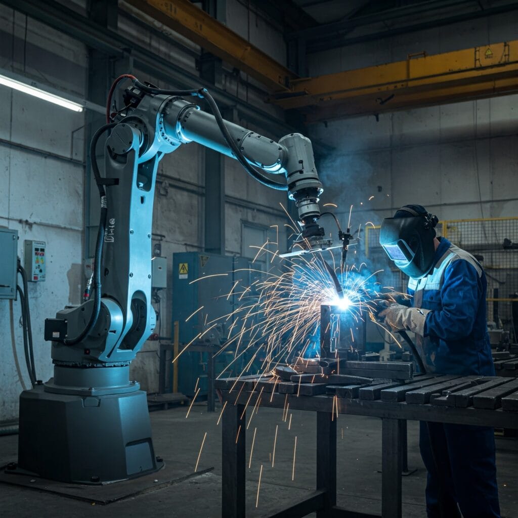
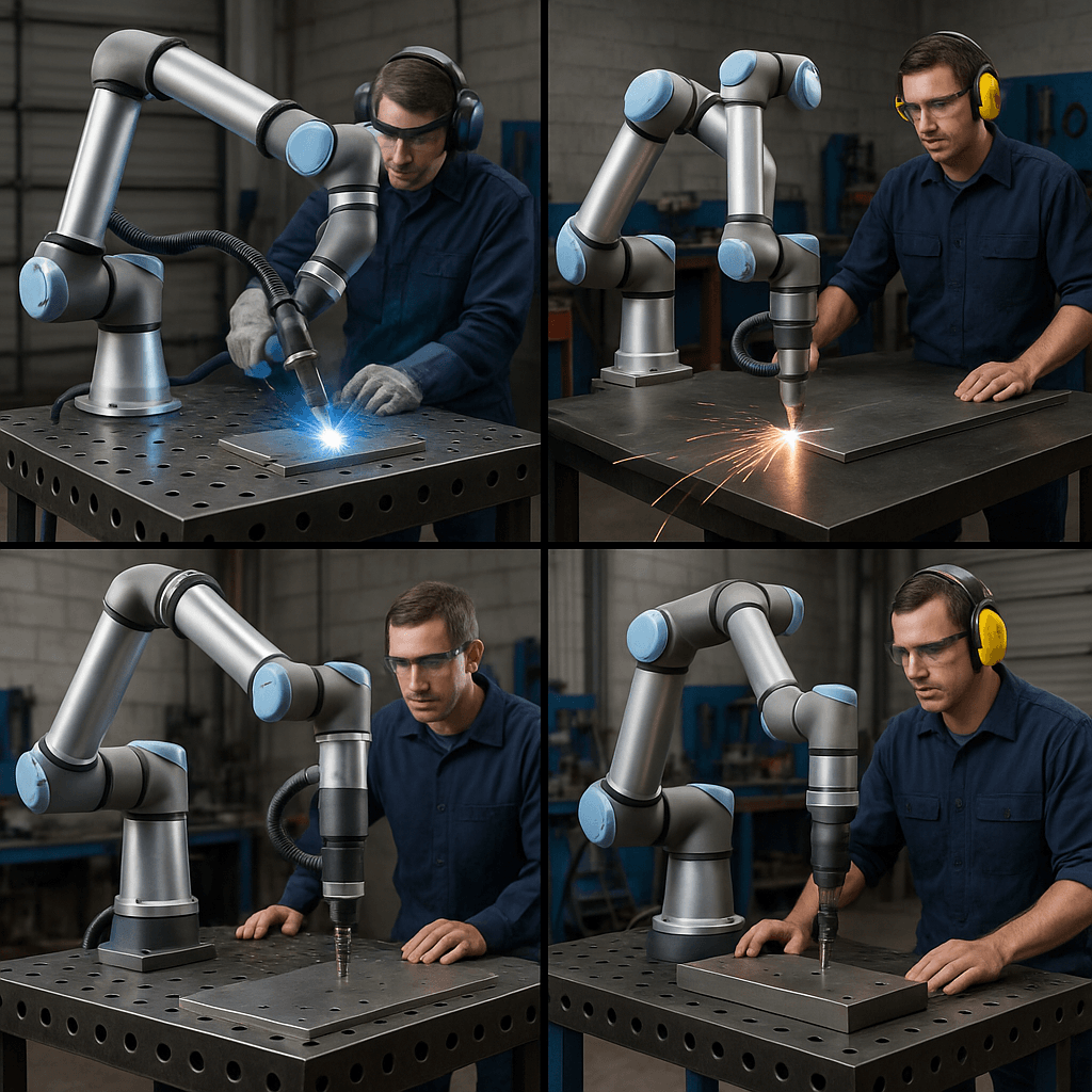
Collaborative robots — universally known as cobots — are reshaping the welding and fabrication industry by bridging the gap between manual craftsmanship and full robotic automation. Unlike traditional industrial robots that operate in isolated, guarded cells entirely separated from human workers, cobots are engineered to work side by side with human operators in shared workspaces, combining the dexterity and judgement of an experienced welder with the precision and consistency of a controlled mechanical system. The result is a manufacturing model that is simultaneously safer, more flexible, and more productive than either all-manual or all-automated approaches.
The timing of the cobot revolution aligns directly with two converging pressures on fabrication businesses: a deepening shortage of qualified welders across most industrialised economies, and the demand for smaller batch sizes and faster changeover as customers move away from long production runs. Traditional industrial robots are expensive to integrate, require specialist programming, and are difficult to retask — making them unsuitable for the small-to-medium production volumes that characterise much of the fabrication sector. Cobots address exactly these pain points: they are typically deployable within days rather than months, reprogrammable by shop floor operators without robotics expertise, and cost-effective even at batch sizes in the hundreds rather than tens of thousands.
This guide covers the complete picture of cobot adoption in welding and fabrication: how cobots work and how they differ from conventional welding robots, the safety standards that govern their use, the welding processes they support, how to evaluate ROI, and the practical considerations for deploying a cobot welding system in your shop. Where relevant, connections are drawn to code compliance under ASME and AWS welding standards.
What is a Cobot? Definition and Core Characteristics
The term collaborative robot (cobot) was coined in 1996 by professors J. Edward Colgate and Michael Peshkin of Northwestern University. The defining characteristic of a cobot is not its physical form but its operating philosophy: it is designed to share a workspace with humans and respond to human presence in a way that prevents injury. This is achieved through a combination of hardware and software safety measures defined by international standards, most notably ISO/TS 15066:2016.
Key physical and functional characteristics that distinguish cobots from traditional industrial robots include:
- Lightweight construction: Most welding cobots weigh between 20 and 35 kg with payload ratings of 3 to 16 kg — manageable enough for a single person to relocate without lifting equipment.
- Force-torque sensing: Built-in joint torque sensors detect unexpected contact forces and halt or retract the arm within milliseconds, preventing crush injuries.
- Speed and separation monitoring: Vision systems and area sensors monitor the distance between the cobot and nearby humans, automatically reducing speed as humans approach.
- Rounded geometry and no pinch points: Cobots are designed with rounded joints and enclosed actuators that reduce the risk of cuts or entrapment on contact.
- Hand-guiding capability: Most cobots can be physically guided through a motion path by a human operator, recording the trajectory for future playback — drastically simplifying programming.
- Open software ecosystems: Leading cobot platforms (Universal Robots, FANUC CRX, KUKA LBR) publish open APIs and maintain ecosystems of plug-and-play peripherals including welding-specific end effectors, wire feeders, and weld process controllers.
Cobots vs. Traditional Industrial Welding Robots
Understanding where cobots fit in the automation landscape requires a clear comparison with traditional industrial robots. The two technologies serve different needs and are not interchangeable in all scenarios.
| Characteristic | Cobot (Collaborative Robot) | Traditional Industrial Robot |
|---|---|---|
| Workspace sharing | Shared with humans | Guarded cell required |
| Typical payload | 3 – 20 kg | 6 – 500+ kg |
| Reach | 500 – 1,300 mm | 500 – 3,200+ mm |
| Speed (max TCP) | 1.0 – 1.5 m/s (collaborative mode) | 2.0 – 10+ m/s |
| Programming | Graphical UI, hand-guiding, tablet | Teach pendant, offline programming software |
| Deployment time | Days to weeks | Weeks to months |
| Capital cost (welding cell) | USD 50k – 150k | USD 150k – 500k+ |
| Redeployment flexibility | High — relocate and retask easily | Low — fixed cell, specialist retasking |
| Best production volume | Low to medium batch (10 – 10,000 pcs) | High volume (>10,000 pcs per year) |
| Safety infrastructure | Minimal — may not require hard guarding | Mandatory safety fencing and interlocks |
Key Benefits of Cobots in Welding and Fabrication
Welding Processes Suited to Cobot Integration
MIG / GMAW Cobot Welding
MIG (Metal Inert Gas) welding, formally known as GMAW (Gas Metal Arc Welding), is the most widely deployed cobot welding process. Its high deposition rate, continuous wire feed, and relatively simple torch geometry make it well-suited to robotic integration. Cobot-compatible GMAW packages from Fronius (TPS/i robotic), Lincoln Electric (Power Wave), and Miller (Auto-Continuum) provide digital communication between the cobot controller and the welding power source, enabling the program to set and log wire speed, voltage, travel speed, and shielding gas flow as part of each weld pass record. This integration is important for code-compliant fabrication, because it produces a verifiable record of welding parameters for each weld run. See the WeldFabWorld GMAW welding guide for the process fundamentals that underpin cobot MIG programming.
TIG / GTAW Cobot Welding
TIG (Tungsten Inert Gas) welding, formally GTAW (Gas Tungsten Arc Welding), presents greater integration challenges than GMAW due to the separate filler wire feed, tungsten electrode management, and the higher skill sensitivity of the process. However, cobot TIG systems are increasingly used for precision applications on stainless steel, aluminium, duplex alloys, and titanium where weld appearance and quality are paramount. Key developments enabling cobot TIG include motorised cold wire feed units that mount on the cobot arm, automatic tungsten cleaning and conditioning stations, and adaptive arc length control using voltage feedback. The GTAW welding guide on WeldFabWorld covers the process parameters that must be correctly programmed in a cobot TIG system.
Submerged Arc Welding (SAW) with Cobots
For heavy plate fabrication — pressure vessels, structural beams, wind tower cans — cobots are finding application in controlling SAW torch positioning and travel along long seams on powered rotators and positioners. The cobot manages torch height, angle, and travel speed while the SAW process handles the high deposition rate butt and fillet welds. This is particularly useful for circumferential shell seams on pressure vessels, where the workpiece rotates on a positioner while the cobot holds the SAW head in a fixed position relative to the seam. See the submerged arc welding guide for the process context.
Laser and Plasma Cutting
Cobots fitted with laser or plasma cutting heads — and guided by vision systems for seam finding — are used for profile cutting, weld preparation bevelling, and trimming of fabricated assemblies. Laser cobot cutting delivers kerf widths of 0.1 to 0.3 mm and heat-affected zones far narrower than plasma or flame cutting, with no tool wear. Plasma cobot cutting is more economical for medium-accuracy work on carbon steel from 3 to 50 mm thickness. Both processes benefit from the cobot’s ability to follow complex 3D paths on formed or irregular workpieces without the fixturing demands of a gantry-type CNC cutter.
Spot and Resistance Welding
Automotive and automotive component fabrication was the first sector to adopt cobots in large numbers for resistance spot welding. Cobot spot welding cells — using servo-controlled C-frame or X-frame spot guns — deliver consistent electrode force, weld time, and hold time across hundreds of spot welds per shift, with minimal electrode maintenance compared to conventional fixed spot welding machines.
Safety Standards and Risk Assessment for Cobot Welding
The safety case for a cobot welding installation is not simply a matter of purchasing a cobot and beginning work. A systematic risk assessment and compliance process is required before any collaborative operation begins. The relevant standards framework includes:
- ISO 10218-1:2011 — Safety requirements for industrial robots (robot design)
- ISO 10218-2:2011 — Safety requirements for industrial robot systems and integration
- ISO/TS 15066:2016 — Collaborative industrial robot systems (the primary cobot standard)
- ISO 12100:2010 — Safety of machinery — Risk assessment and risk reduction
- IEC 62061 — Functional safety of electrical, electronic, and programmable electronic safety-related control systems
The Four Collaborative Operation Modes
ISO/TS 15066 defines four distinct modes of collaborative operation. Understanding which mode applies to your cobot welding deployment is essential for both safety and productivity planning:
| Mode | Description | Typical Welding Use Case | Speed Limit |
|---|---|---|---|
| Safety-rated monitored stop (SMS) | Robot stops when a human enters the collaborative zone; resumes when human exits | Part loading and unloading by operator while cobot holds position | 0 during stop |
| Hand guiding (HG) | Human physically guides the cobot through a path with force-torque feedback | Teaching weld paths for new part programs | No auto motion |
| Speed and separation monitoring (SSM) | Cobot slows progressively as human approaches; stops before contact | Operator checking weld quality while cobot continues to adjacent area | Proportional to distance |
| Power and force limiting (PFL) | Cobot limits contact forces to biomechanically safe levels if it touches a human | Most common mode during collaborative welding — operator can work adjacent to the moving cobot | Typically ≤250 mm/s in shared zone |
Programming and Deploying a Cobot Welding System
Hardware Selection
A complete cobot welding system consists of several integrated components that must be specified together:
- Cobot arm: Payload and reach must accommodate the welding torch assembly (typically 1.5 to 3 kg for a MIG torch with cable) with margin. Universal Robots UR10e (12.5 kg payload, 1,300 mm reach) and FANUC CRX-10iA are popular choices for welding.
- Welding power source: Must support digital communication with the cobot controller, typically via EtherNet/IP, Profibus, or DeviceNet. Fronius TPS/i, Lincoln Electric Power Wave, and Miller Deltaweld series are commonly integrated.
- Wire feeder: A push-pull system minimises wire feed resistance over long cable distances. The feeder must be mounted to minimise cable management complications as the cobot arm articulates through its range of motion.
- Welding torch: Cobot-rated MIG torches (Binzel RAB, Tregaskiss, Fronius PushPull Flex) are reinforced and designed with cable arrangements that tolerate the torsional loads imposed by cobot wrist rotation.
- Fixturing and positioner: Accurate, repeatable fixturing is more critical for cobot welding than for manual welding, because the cobot follows a programmed path rather than adapting visually to fit-up variation. Quick-change fixture plates compatible with the cobot base mounting system allow fast job changeover.
- Fume extraction: Localized fume extraction mounted at the torch (on-torch extraction) or positioned directly above the weld zone is required. The operator’s collaborative working position must be upwind of the fume plume.
Programming Methods
Three principal programming methods are used in cobot welding, often in combination:
- Hand-guiding: The operator holds the cobot wrist or a handle mounted near the end effector and physically moves the arm through the desired weld path while the controller records waypoints. Fast and intuitive for simple seams; impractical for complex multi-pass sequences.
- Graphical teach pendant: A touchscreen interface (Universal Robots Polyscope, FANUC iPendant) allows programming of move types (linear, arc-interpolated, joint), welding parameter calls, and logic (IF/THEN, loops, force events) without writing code. Welding-specific software overlays (Hirebotics Beacon, Vectis, Pemamek PEMA) add welding process nodes directly to the graphical program flow.
- Offline programming (OLP): CAD-based software (RoboDK, OCTOPUZ, Delfoi) imports the part geometry, simulates the cobot motion, and generates a collision-checked program that is uploaded to the cobot. OLP eliminates the need to occupy the cobot for programming and is essential for complex multi-pass welds or large weldments where hand-guiding is impractical.
ROI Calculation for a Cobot Welding Cell
Evaluating the financial return on a cobot welding investment requires a structured analysis of costs and savings. The following framework covers the principal variables.
Leading Cobot Manufacturers and Welding-Specific Ecosystems
| Manufacturer | Platform | Payload / Reach | Welding Ecosystem Partners | Market Position |
|---|---|---|---|---|
| Universal Robots | UR5e, UR10e, UR16e | 5–16 kg / 850–900 mm | Fronius, Lincoln, Miller, Hirebotics, Vectis, Pemamek | Market leader |
| FANUC | CRX-10iA, CRX-25iA | 10–25 kg / 1,249–1,889 mm | Lincoln Electric, Miller, custom OEM packages | Strong in automotive |
| KUKA | LBR iisy 11, LBR iisy 15 | 11–15 kg / 1,200 mm | Fronius, Binzel, EWM | Strong in Europe |
| ABB | GoFa CRB 15000 | 5 kg / 950 mm | Lincoln Electric, custom | Growing cobot range |
| Doosan Robotics | M0609, M1013, M1509 | 6–15 kg / 900–1,500 mm | Lincoln, Fronius, custom | Emerging, competitive pricing |
Industry 4.0 Integration and Digital Weld Records
One of the most significant advantages of cobot welding over manual welding — and one that is often underappreciated — is the digital data that cobot welding systems generate automatically. Every weld run can be logged with its exact parameters: wire feed speed, arc voltage, travel speed, shielding gas flow, weld start and end time, and any fault or deviation events. This data constitutes a digital weld record that can be stored against the work order, the weld joint identification, and the welder qualification record.
For fabrication under ASME codes, AWS structural codes, or EN standards, this automatic parameter logging provides an objective, tamper-evident record that a weld was made within the ranges of the qualified WPS. Manual weld records depend on the welder manually logging parameters or on a QC inspector recording spot checks — neither approach captures the complete history of each weld pass. Cobot weld data logging represents a step-change in welding traceability that aligns directly with the quality assurance demands of pressure vessel, oil and gas, and nuclear fabrication.
Beyond traceability, cobot welding data feeds into overall equipment effectiveness (OEE) monitoring — tracking arc-on time, idle time, fault events, and consumable consumption across multiple cobot cells. This operational data is the foundation for continuous improvement programmes and forms a natural complement to the ASME Section IX qualification records that underpin the weld procedure qualification framework.
Cobot Welding and Code Compliance (ASME Section IX, AWS D1.1)
A question frequently raised by CWI inspectors and QA managers is whether cobot welds can be code-compliant under ASME Section IX or AWS D1.1. The short answer is yes, subject to the same qualification requirements that apply to any mechanised or automatic welding process.
Under ASME Section IX, QW-100 defines welding as manual, semiautomatic, machine (mechanised), and automatic. Cobot welding generally falls into the machine or automatic category, depending on whether a human operator makes adjustments during welding. The WPS and PQR must be qualified under QW-200 and QW-300 respectively, using test coupons produced by the cobot system under representative production conditions. The essential variables that must be controlled within the qualified ranges include travel speed, wire feed speed (proportional to heat input), joint geometry, base metal and filler metal classification, and preheat and interpass temperature where applicable.
For materials requiring preheat — such as P91 chrome-moly alloy steel covered in the WeldFabWorld guide on P91 welding requirements — the cobot system must include a verified preheat monitoring method (contact thermometer or thermal camera) integrated into the program, halting welding if interpass temperature falls below or exceeds the WPS limits. Similarly, carbon equivalent assessment using the carbon equivalent calculator determines the minimum preheat requirement that the cobot program must enforce.
Addressing the Welder Shortage: Cobots and the Human Workforce
A persistent concern about cobot (and robot) adoption in welding is the impact on welding employment. The reality in fabrication shops that have adopted cobots is more nuanced than simple job displacement. In most cases, the cobot takes over arc-on time — the physically demanding, hazardous, and repetitive part of the job — while the human welder shifts to tasks that require judgement and adaptability: fit-up, tack welding, inspection, fixture setup, and program management.
Rather than eliminating welding jobs, cobots are more often eliminating the welding vacancies that shops cannot fill. The American Welding Society’s workforce shortage projections — a deficit of over 300,000 welders in the United States by 2028 — reflect a structural supply problem that cobot adoption helps mitigate without requiring shops to find and hire additional qualified welders they cannot recruit. In India, where labour costs are lower and the welder supply remains relatively more abundant than in Western markets, the ROI case for cobots is more dependent on quality consistency and throughput than on direct labour replacement.
The long-term workforce implication is a shift in the skills profile of the welding workforce: shops need fewer all-manual welders and more hybrid welding technicians capable of programming, setting up, and troubleshooting cobot welding systems. This is an opportunity for welding training organisations to update curricula and for individual welders to add automation competency to their credentials — increasing both employability and earning potential in a sector where human-robot collaboration is becoming the norm rather than the exception.
Recommended Books on Welding Automation and Cobots
These references are widely used by welding engineers, automation specialists, and fabrication managers evaluating or deploying cobot and robotic welding systems.
Disclosure: WeldFabWorld participates in the Amazon Associates programme (StoreID: neha0fe8-21). If you purchase through these links, we may earn a small commission at no extra cost to you. This helps support free technical content on this site.