Welding of P91 Steel —
Complete Requirements Guide
Grade P91 (modified 9Cr-1Mo-V) is the most technically demanding material in power plant and high-temperature piping fabrication. Every stage — from preheat and hydrogen bake-out through PWHT temperature selection and Mn+Ni control — requires precision and discipline. This definitive guide covers every requirement, cross-referenced to ASME Section I, VIII, B31.1, and B31.3.
What Is P91 Steel? — The CSEF Family
P91 steel — formally modified 9Cr-1Mo-V (9% chromium, 1% molybdenum, vanadium-niobium-nitrogen modified) — belongs to the family of Creep Strength Enhanced Ferritic (CSEF) steels. These are advanced alloy steels engineered to maintain high mechanical strength and resist creep deformation at elevated operating temperatures up to 610°C, where conventional chrome-moly steels (P11, P22) reach their performance limits.
The material designation “P91” follows ASME pipe grade nomenclature. The same composition appears as T91 (tube), F91 (forging), and in specifications SA-335 P91 (pipe), SA-213 T91 (tube), and SA-182 F91 (forging). European equivalent: X10CrMoVNb9-1 (EN 10216-2). In ASME Section IX, it is classified as P-Number 15E — a designation reflecting its special qualification requirements.
Other CSEF steels in the same family — P/T92, P/T22, P/T23, E911, P/T122 — have been developed by further modifying the base 9Cr-1Mo composition for ultra-supercritical (USC) power plant applications. Each shares many P91 welding principles but with modified temperature windows and consumable requirements. For the complete introduction to ASME P-numbers, see our guide on P-Number, F-Number & A-Number in ASME.
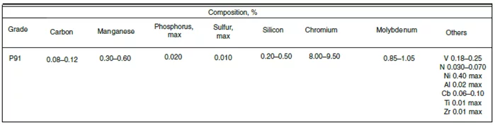
Chemical Composition of P91 — Role of Each Element
The superior properties of modified 9Cr-1Mo (P91) over conventional 9Cr-1Mo steel are achieved through carefully controlled additions of vanadium, niobium, and nitrogen, combined with tight control of carbon, nickel, manganese, aluminium, and residual elements. Each element plays a specific metallurgical role — and each has consequences if out of specification.
| Element | Role in P91 | Effect if Too High | Effect if Too Low |
|---|---|---|---|
| Carbon (C) | M23C6 carbides + MX carbo-nitrides; austenite stabiliser | Weldability problems; excess hardness | Insufficient carbide precipitation; loss of creep strength |
| Chromium (Cr) | Oxidation & corrosion resistance; hardenability; M23C6 former | Delta ferrite formation; toughness reduction | Inadequate oxidation resistance in steam |
| Molybdenum (Mo) | Solid solution strengthening; retards carbide coarsening | Laves phase (Fe₂Mo) at high temperature | Reduced high-temperature strength |
| Vanadium (V) | Fine MX carbonitride former; pins grain boundaries — critical for creep strength | Excess precipitation; embrittlement | Insufficient creep strengthening; fails Grade 91 properties |
| Niobium (Nb) ≥0.03% | NbC, NbN carbonitrides; grain refinement; creep strengthening | Excess NbC; reduced toughness | Insufficient carbonitride formation; loss of creep strength |
| Nitrogen (N) ≥0.02% | MX carbonitrides with Nb & V; austenite stabiliser | Porosity risk; excess delta ferrite retardation | Insufficient MX density; reduced creep strength |
| Nickel (Ni) ≤0.40% | Lowers Ac1 temperature; toughness improvement in small amounts | >0.4%: depresses Ac1 → narrows PWHT window; >0.6%: reduces creep resistance | Reduced low-temperature toughness |
| Manganese (Mn) ≤0.60% | Deoxidiser; minor strengthening; with Ni controls Ac1 | Mn+Ni >1.0%: lowers Ac1; >1.5%: drops Mf → retained austenite risk | Reduced deoxidation; toughness concerns |
⚠️ Mn+Ni Control Is Safety-Critical
The sum of Mn+Ni is the single most important chemical parameter in P91 filler metal procurement. As Mn+Ni exceeds 1.0%, the lower critical temperature (Ac1) drops — narrowing the safe PWHT window. Above 1.5%, the martensitic finish temperature (Mf) drops below 96°C, risking retained austenite in the completed weld joint. Always purchase filler metals with certified heat-lot chemical analyses showing actual Mn+Ni values — classification certificates alone are insufficient.
Where P91 Steel Is Used
🔥 Power Generation
- Superheaters & Reheaters (SA-213 T91 tubes): 540–600°C, thin wall, tube-to-header welds
- Main Steam Headers (SA-335 P91 pipe / SA-182 F91 forgings): large-bore, thick-wall, high inspection category
- Main Steam Lines: HP turbine connections — 100% RT or UT required on all welds
- Hot Reheat Lines: lower pressure but equally high temperature
- Turbine Casings & Bypass Valves: cast/forged P91 — repair welding follows same strict protocol as new fabrication
🏭 Petrochemical & Refining
- High-temperature process reactors: where H₂ partial pressure and temperature combine
- Fired heater transfer lines: sustained high-temperature creep service
- Hydrocracker & reformer piping: where both strength and hydrogen resistance are required
- Heat recovery steam generators (HRSG): combined-cycle power plants
Why P91 over P22? P91 maintains significantly higher allowable stress above 500°C — allowing thinner wall sections for the same pressure rating. This reduces weight, thermal inertia, and startup time in large-diameter headers and steam lines. The trade-off is the far more demanding welding procedure. For more on creep-resistant materials, see our guide on Heat Treatment for Fabricators.
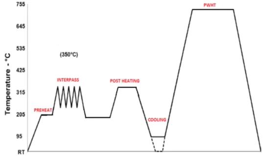
The P91 Welding Cycle — Complete Step-by-Step Sequence
Welding P91 is not a single operation — it is an integrated thermal cycle where each step is metallurgically dependent on the previous one. Planning must begin before the first arc is struck and extend until the post-PWHT inspection is complete.
Cutting, Edge Preparation & Fit-Up Requirements
- Machine cutting preferred: Band saw recommended. When thermal cutting (gas or plasma) is used, at least 3 mm must be removed by machining from the cut surface before welding
- Edge NDE: All edge preparations must undergo LPT or MT after preparation and before welding — weld build-up on edge preparations is prohibited
- ID/OD matching: Both inside and outside diameters must be verified at fit-up before tacking
- Root gap: 2–3.5 mm. Misalignment: 1.0 mm maximum
- Fit-up method: NB ≥150 mm → clamping; NB <150 mm → bridge tack using P91 filler material. Preheat to 204°C minimum before tack welding
- Joint cleaning: Stainless steel wire brush only — carbon steel tools are prohibited (iron contamination)
- Purging: Inert gas purge required on bore side for GTAW root passes
- Thermocouple attachment: By capacitor discharge welding at ≥3×wall thickness or 75 mm from weld edge (whichever is greater); two thermocouples 180° apart each side; temperature difference between readings ≤10°C
Preheat Requirements for P91 Welding
Preheat is mandatory without exception for all welding on P91. It reduces the cooling rate through the martensitic transformation range (preventing hydrogen-induced cracking), drives hydrogen out of the joint, and reduces the thermal gradient across the weld (lowering residual stress).
Tack welds also require preheat: The 204°C minimum preheat must be established and verified before any tack welding, not just before production welding. Tack welds deposited without preheat on P91 create untempered martensite that becomes the initiation point for delayed hydrogen cracking — a classic root cause of P91 weld failures in the field.
Hydrogen Bake-Out — Why It Is Mandatory for P91
P91 forms a fully martensitic microstructure during cooling from welding. Martensite has high dislocation density, residual tensile stress, and very low ductility in the as-deposited condition. Hydrogen absorbed during welding — from flux moisture, surface contamination, or the atmosphere — becomes trapped in this hard microstructure as the joint cools. If not removed before PWHT, it can initiate delayed hydrogen-induced cracking (HICC) in the HAZ, sometimes weeks after welding.
Complete welding — do not cool
Immediately after completing welding, do not allow the joint to cool below preheat temperature. Begin transitioning to post-heat temperature without interruption.
Raise to post-heat temperature
Heat the joint using electric resistance heating to 300–350°C. For GTAW-only welds, the minimum may be reduced to 260°C where permitted by the governing code, because GTAW weld metal contains significantly less hydrogen than SMAW or FCAW deposits.
Hold at post-heat temperature
Maintain post-heat temperature for minimum 2 hours, maximum 3 hours. This soak allows hydrogen to diffuse out at a temperature high enough for rapid diffusion but low enough to avoid premature tempering of the martensite before PWHT.
Wrap with insulation — slow cool
Wrap the joint with ceramic fibre blanket insulation and allow slow cooling to at least 96°C. The martensitic finish (Mf) temperature of P91 is approximately 96°C — the weld must cool completely through and below this temperature before PWHT is initiated. Cooling to below 90°C is recommended to ensure complete transformation.
Examine before PWHT
After removal of insulation, carry out visual examination of the weld and HAZ. Any surface indications must be repaired before PWHT. Proceed to RT or UT as applicable.
PWHT within 5 days
There shall be no delay of more than 5 days between completion of hydrogen bake-out and commencement of PWHT. If PWHT cannot be performed within 5 days, the joint must receive an additional hydrogen bake-out before PWHT proceeds.
PWHT of P91 Steel — The Most Critical Step
PWHT is the most critical step in the entire P91 fabrication sequence. Its purpose is to temper the hard, brittle martensite formed during welding, restoring toughness, reducing hardness, and relieving residual stresses. Without correct PWHT, P91 welds cannot achieve the mechanical properties required for safe high-temperature creep service.
The PWHT temperature window for P91 is bounded above by the Ac1 temperature (where austenite begins to reform). If the PWHT temperature exceeds Ac1, fresh untempered martensite forms on cooling — causing high hardness, brittleness, and loss of creep strength. The Ac1 temperature is not fixed; it decreases as Mn+Ni content increases:
| Code | Min PWHT Temp | Max PWHT Temp | Hold Time | Reference |
|---|---|---|---|---|
| ASME Section I | 705°C (1300°F) | 785°C (1450°F) | 1 hr/25 mm (min 1 hr) | Table PW-39-5 |
| ASME Section VIII Div.1 | 705°C (1300°F) | 780–790°C (Mn+Ni dependent) | 1 hr/25 mm (min 1 hr) | Table UCS-56-11 |
| ASME B31.1 | 705°C (1300°F) | 775°C (1425°F) | 1 hr/25 mm (min 1 hr) | Table 132.1.1-1 |
| ASME B31.3 | 705°C (1300°F) | 775°C (1425°F) | 1 hr/25 mm (min 1 hr) | Table 331.1.1 |
| Industry Recommended | 740°C | 760°C | 2–4 hr (heavy sections) | Industry consensus |
⚠️ PWHT Temperature Is Safety-Critical — Both Directions
Too low (<705°C): Insufficient tempering — weld remains hard, brittle, susceptible to stress corrosion and low-temperature brittle fracture in service. Too high (>Ac1): Re-austenitisation → fresh untempered martensite on cooling → re-hardening and loss of creep strength. Both errors cause premature weld joint failure. Always verify actual Ac1 from the certified filler metal chemistry before setting the PWHT upper limit. Learn more about PWHT in our Heat Treatment for Fabricators guide.
Simulation PWHT for PQR coupons: When P91 procedure qualification test coupons (PQR) must undergo simulated PWHT cycles to replicate service heat treatment, specific rules apply under ASME Section IX. See our dedicated article on Simulation Heat Treatment Requirements per ASME.
Consumable Selection for P91 Welding
The performance of any Grade 91 weld depends entirely on achieving the correct chemical analysis in the deposited weld metal. Consumables must be purchased with certified heat-lot chemical analyses — standard classification certificates alone are insufficient for P91. The actual Mn+Ni sum for the specific lot must be verified before welding commences.
| Process | AWS Classification | ASME SFA | Critical Notes |
|---|---|---|---|
| SMAW (MMA) | E9015-B9 | AWS A5.5 | EXX15 type preferred — no iron powder in coating reduces residual element contamination sources. Electrodes must be stored in heated rod ovens at welding location. |
| GTAW (TIG) | ER90S-B9 | AWS A5.28 | Low-hydrogen process — post-heat may be reduced to 260°C for GTAW-only welds. Preferred process for root passes on pipe joints. |
| SAW | EB9 + basic flux | AWS A5.23 | Basic flux mandatory — other flux types burn out carbon and elevate oxygen/nitrogen, degrading strength and toughness. Verify flux basicity index. |
| FCAW | E91T1-B9 | AWS A5.29 | Limited to applications where specifically qualified. Check for low-hydrogen designation. Verify deposited chemistry independently. |
Critical Weld Metal Chemistry Requirements
✅ Minimum Requirements (must meet)
- Carbon ≥ 0.09% — for adequate M23C6 and MX carbide precipitation
- Niobium ≥ 0.03% — NbC/NbN precipitation for creep strengthening
- Nitrogen ≥ 0.02% — MX carbonitride formation with Nb and V
⚠️ Maximum Limits (must not exceed)
- Mn+Ni ≤ 1.5% — above 1.5% Mf drops below 96°C → retained austenite risk
- Mn+Ni ≤ 1.0% — to stay within 740–760°C recommended PWHT range
- Residual elements (P, S, Sn, Sb, As, Pb, Cu) — as low as practically achievable
Quality indicator — crater cracks: If solidification crater cracks are observed at weld bead craters, this reliably indicates elevated residual elements in the filler metal, regardless of the certified test report. Any consumable showing crater cracking should be immediately removed from service and returned to the supplier. This simple visual check is an effective early warning for contaminated P91 consumables. For more on consumable selection and nomenclature, see our Welding Consumable Nomenclature guide.
For the specific debate between E9015-B9 and E9018-B9 — why E9015 is preferred over E9018 for P91 — see our detailed answer in the Welding & QA/QC Interview Questions guide (Question 11) and our dedicated article on E9015-B91 vs E9018-B91 comparison.
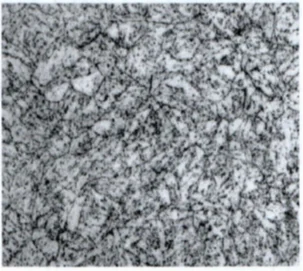
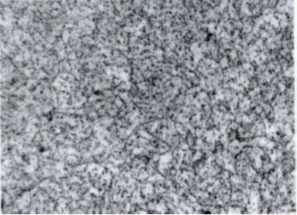
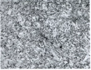
P91 Microstructure — What Correct PWHT Achieves
The target microstructure for P91 after correct normalise-and-temper (base material) or PWHT (weld and HAZ) is tempered martensite — a fine lath-martensitic structure with a homogeneous distribution of carbide and carbonitride precipitates. The two critical precipitate families are:
- M23C6 carbides (primarily chromium-rich): decorate lath boundaries and prior austenite grain boundaries — pin boundaries and retard recovery and recrystallisation during creep
- MX carbonitrides (VN, VC, NbC, NbN): extremely fine precipitates within the martensite laths — the primary creep-strengthening phase; pin dislocations and sub-grain boundaries directly resisting creep deformation
Welding and Heating Interruptions — Required Procedures
The long P91 fabrication cycle and critical importance of continuous heat application mean that interruptions must be planned for and managed according to defined procedures. The following table summarises the required actions for each interruption scenario:
| Interruption Point | Required Action | Critical Rule |
|---|---|---|
| Power failure before preheat reached | Allow to cool to ambient; restart preheat from ambient when power restored | No metallurgical impact at this stage — full restart required |
| Power failure after preheat achieved, before welding | Maintain temperature by alternative means (LPG, diesel generator). If joint cools, repeat full preheat cycle | Joint must never drop below preheat minimum during transition |
| Power failure during H₂ bake-out | Switch immediately to diesel generator or LPG heating. Full bake-out hold time must be completed at correct temperature — clock runs only at full temperature | Time at under-temperature does NOT count toward bake-out duration |
| Power failure during PWHT heating ramp | If temperature drop ≤50°C: resume and continue. If >50°C: restart entire PWHT cycle from beginning | 50°C drop threshold — check project specification for specific limits |
| Power failure during PWHT soak | When temperature restored, add holding time equal to duration of under-temperature period to the remaining minimum soak time | Total soak time at temperature must be achieved — partial credit for time at reduced temperature only if within ±14°C of minimum per some codes |
| Power failure during PWHT cooling | Above unloading temp (315°C): raise back to soaking temperature, hold additional required period. Below 315°C: continue natural cooling — no action required | 315°C unloading temperature is typical — verify against applicable code |
| Welder change during welding | Maintain preheat temperature throughout transition. Record each welder’s deposited thickness individually in the weld traveller. Replacement welder must be qualified for the applicable WPS | Documentation continuity is a code requirement — missing records = non-conformance |
Post-PWHT Hardness Targets
After correct PWHT, hardness testing (typically Vickers HV10) across the weld, HAZ, and base metal confirms that the tempering treatment was effective. The target range for P91 after PWHT is:
🛒 Recommended Tools & References for P91 Welding
These professional resources and instruments support correct P91 welding execution — from temperature verification tools to authoritative technical references.
Disclosure: WeldFabWorld participates in the Amazon Associates Programme. Purchases via these links may earn a small commission at no additional cost to you, supporting our free technical content for the welding community.
P91 Welding — FAQs
🎯 Test Your P91 & ASME Code Knowledge
P91 preheat, PWHT, Mn+Ni control, and P-Number 15E qualification are frequent examination topics for CSWIP, AWS CWI, and QA/QC interviews.