Weld Joint Strength Reduction Factor (W) — ASME B31.3 Code Perspective
The Weld Joint Strength Reduction Factor (W) is one of the most consequential design parameters in high-temperature process piping engineering, yet it is frequently overlooked in routine calculations. ASME B31.3-2024 mandates its application through Table 302.3.5-1 for materials and temperature ranges where the creep and thermal degradation behaviour of the weld zone differs materially from the surrounding parent metal. Ignoring Factor W in an applicable scenario is not conservative — it is a non-compliant design that can result in premature weld creep failure decades before the planned service life ends.
This guide covers everything a piping engineer or inspector needs to know: what Factor W is and why it exists, the metallurgical mechanisms that drive weld strength reduction at elevated temperatures, a complete walk through Table 302.3.5-1 for carbon steel, CrMo steels, Creep-Strength-Enhanced Ferritic (CSEF) steels including P91 (Grade 91), and austenitic stainless steels, worked calculation examples, and how to integrate W into wall thickness and allowable stress evaluations. An interactive calculator is provided to compute adjusted weld allowable stress for any material and temperature combination.
Weld Allowable Stress Calculator (Factor W)
What is the Weld Joint Strength Reduction Factor W?
Factor W is a dimensionless multiplier in the range 0.5 ≤ W ≤ 1.0 that is applied to the base metal allowable stress to arrive at the effective allowable stress at a weld joint when operating in the elevated-temperature creep regime. It appears in ASME B31.3 Table 302.3.5-1 and is incorporated into the allowable stress term used for pressure design calculations.
The physical meaning is straightforward: a W value of 1.0 means the weld zone is as strong as the parent material under creep conditions and no reduction is required. A value of 0.71 means the weld joint retains only 71% of the parent metal’s long-term rupture strength at that temperature, and the design stress must be reduced accordingly. A W of 0.5 — the minimum listed in the current code — means the weld is at most half as strong as the base metal in long-term service.
Why Welds Lose Strength at Elevated Temperatures
To understand why Factor W is necessary, you need to understand the metallurgical events that take place in a weld joint during and after welding, and how these affect long-term performance in the creep regime.
The Heat-Affected Zone (HAZ) and Its Microstructural Zones
A weld in a ferritic steel creates several distinct microstructural zones. Moving from the weld centreline outward through the base metal, these are: the weld metal itself, the coarse-grained HAZ (CGHAZ), the fine-grained HAZ (FGHAZ), the inter-critical HAZ (ICHAZ), and the over-tempered base metal. Each zone experiences a different peak temperature during welding and therefore develops a different microstructure.
For P91 and other CSEF steels, the FGHAZ and ICHAZ are the most critical regions. These zones experience temperatures that partially or fully austenitise the steel and then re-transform on cooling to martensite with a lower dislocation density and coarser precipitate distribution than the optimally tempered base metal. Under creep loading, these “soft zones” accumulate damage preferentially — a failure mode known as Type IV cracking.
Type IV Cracking
Type IV cracking is the dominant creep failure mode for CrMo and CSEF steels in high-temperature service. It initiates and propagates in the FGHAZ or ICHAZ at the HAZ-base metal boundary, forming a fracture path that runs parallel to but just outside the weld. Unlike weld metal or CGHAZ failures, Type IV cracks are often difficult to detect by conventional radiography because they run along a narrow band with complex geometry. Phased-array ultrasonic testing (PAUT) is the preferred method for in-service detection.
Factor W in ASME B31.3 is essentially a quantification of the Type IV susceptibility of different material groups — lower W values indicate higher susceptibility to premature weld zone failure in the creep regime.
Creep Mechanisms in Austenitic Stainless Steels
For austenitic stainless steels such as Grade 304H, 316H, and 347H, the weld strength reduction mechanism is different. These materials rely on grain boundary strengthening and precipitation of carbides at grain boundaries for creep resistance. Welding and the associated thermal cycle can dissolve or redistribute these precipitates, creating a sensitised or depleted microstructure in the HAZ that has lower creep rupture strength than the parent metal. This is separate from the weld decay (sensitisation) phenomenon, though both have the same root cause: carbide precipitation behaviour in the HAZ.
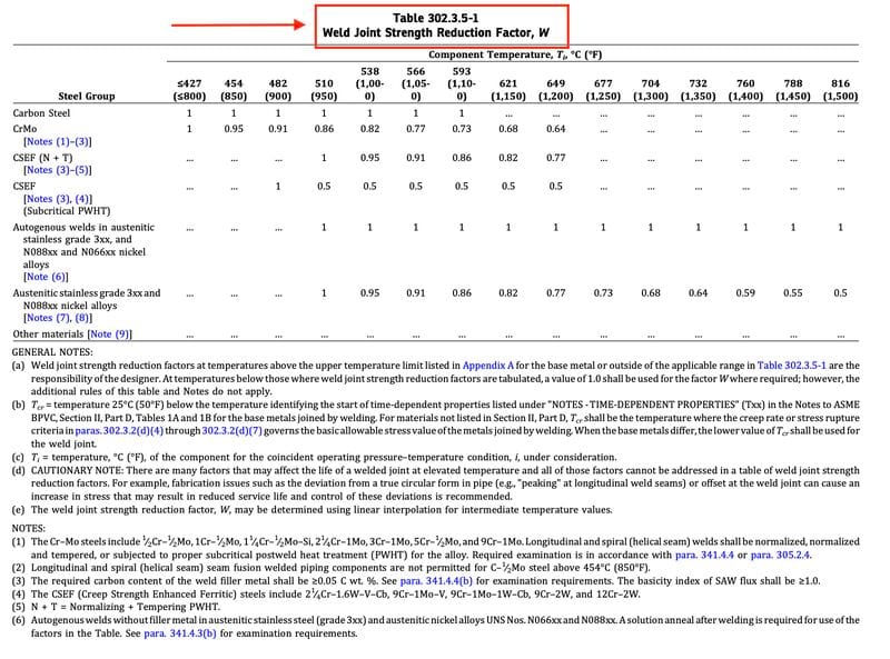
ASME B31.3 Table 302.3.5-1 — W Factor Values by Material and Temperature
The following table presents representative W values from ASME B31.3-2024 Table 302.3.5-1 for the most commonly used steel groups in high-temperature piping. Always consult the current edition of the code for the definitive values applicable to your specific material and specification.
| Temperature (°C / °F) | Carbon Steel (P-No.1) | 1¼Cr-½Mo P11/T11 (P-No.4) | 2¼Cr-1Mo P22/T22 (P-No.5A) | Grade 91 9Cr-1Mo-V (P-No.5B) | Grade 92 (P-No.5B) | SS 304/316H (P-No.8) |
|---|---|---|---|---|---|---|
| ≤427°C / ≤800°F | 1.00 | 1.00 | 1.00 | 1.00 | 1.00 | 1.00 |
| 482°C / 900°F | 1.00 | 1.00 | 1.00 | 1.00 | 1.00 | 1.00 |
| 510°C / 950°F | 1.00 | 0.95 | 0.95 | 1.00 | 1.00 | 0.95 |
| 538°C / 1000°F | 1.00 | 0.91 | 0.91 | 0.95 | 0.95 | 0.91 |
| 566°C / 1050°F | 1.00 | 0.86 | 0.86 | 0.91 | 0.91 | 0.86 |
| 593°C / 1100°F | 1.00 | 0.80 | 0.80 | 0.87 | 0.87 | 0.82 |
| 621°C / 1150°F | 1.00 | 0.74 | 0.74 | 0.80 | 0.80 | 0.77 |
| 649°C / 1200°F | 1.00 | 0.67 | 0.67 | 0.71 | 0.71 | 0.72 |
| 677°C / 1250°F | 1.00 | 0.60 | 0.58 | 0.64 | 0.64 | 0.67 |
| 704°C / 1300°F | 1.00 | 0.54 | 0.51 | 0.58 | 0.58 | 0.62 |
| 732°C / 1350°F | 1.00 | 0.50 | 0.50 | 0.50 | 0.50 | 0.57 |
| 816°C / 1500°F | 1.00 | — | — | — | — | 0.50 |
Note: Values in this table are illustrative based on the structure of ASME B31.3-2024 Table 302.3.5-1. Always verify against the current edition of the code for your specific material specification and service conditions. Intermediate temperature values should be interpolated linearly.
How to Apply Factor W in Pressure Design
Factor W enters the pressure design calculation through the allowable stress term. The basic hoop stress (Barlow) formula for pipe wall thickness in ASME B31.3 is:
Where:
tm = minimum required wall thickness (mm or in)
P = internal design pressure (MPa or psi)
d = outside diameter of pipe (mm or in)
S = allowable stress from Appendix A (MPa or psi)
E = weld joint quality factor (from Table A-1B)
W = weld joint strength reduction factor (Table 302.3.5-1)
Y = coefficient from Table 304.1.1
Notice that W and E both appear in the denominator alongside S. A lower W value directly increases the required wall thickness. For materials where both E < 1.0 and W < 1.0 apply simultaneously, the combined effect can be substantial — this is why accurate identification of the applicable W value at design stage is so important.
Worked Examples — Factor W in Practice
Example 1: P91 Superheater Steam Line at 600°C
A superheater steam line uses Grade 91 seamless pipe. The design conditions are 18 MPa at 600°C. The base allowable stress for P91 at 600°C (interpolated from ASME B31.3 Appendix A) is approximately 96 MPa. The pipe outside diameter is 219.1 mm. Determine the adjusted weld allowable stress and the minimum wall thickness at a circumferential butt weld.
W = 0.87 – 0.25 × (0.87 – 0.80) = 0.87 – 0.0175 = 0.852
Step 2 — Adjusted weld allowable stress Sweld = S × W = 96 × 0.852 = 81.8 MPa
Step 3 — Minimum wall thickness (E=1.0 for seamless, Y=0.4) tm = (P × d) / (2 × (S × E × W + P × Y))
tm = (18 × 219.1) / (2 × (96 × 1.0 × 0.852 + 18 × 0.4))
tm = 3943.8 / (2 × (81.8 + 7.2))
tm = 3943.8 / (2 × 89.0) = 3943.8 / 178 = 22.2 mm Add mill undertolerance (typically 12.5%) for selected wall thickness.
Example 2: P22 Reformer Tube Connection at 649°C
A high-temperature reformer in a fertiliser plant uses 2¼Cr-1Mo (P22) piping at 649°C and 8.5 MPa. The base allowable stress at 649°C is 45 MPa. What is the effective weld allowable stress?
Step 2 — Adjusted weld allowable stress Sweld = 45 × 0.67 = 30.2 MPa This is a 33% reduction from the base metal allowable. This is why P22 has been
largely replaced by P91 and P92 in new high-temperature refinery designs.
Factor W by Material Group — Engineering Perspective
Carbon Steel (P-No. 1)
Carbon steel retains W = 1.0 across all code-applicable temperatures in Table 302.3.5-1. This does not mean carbon steel welds are immune to degradation at elevated temperatures — it means that carbon steel is typically not used above its Appendix A upper temperature limit of around 427°C (800°F) for long-term service. Above this temperature, oxidation and graphitisation become governing concerns, and the code limits use of carbon steel rather than applying a weld reduction factor.
CrMo Steels: P11 (1¼Cr-½Mo) and P22 (2¼Cr-1Mo)
These steels, commonly designated P11/T11 and P22/T22 in ASME nomenclature (see the P-Number and material grouping guide), are used extensively in power generation and refinery steam services. Their W factors drop steadily above 510°C, reaching the code minimum of 0.50 at 732°C. P22 sees a more aggressive reduction than P11 at very high temperatures because its higher chromium and molybdenum content, while beneficial for oxidation resistance, makes it more susceptible to sigma phase and other embrittlement phenomena.
In new plant designs above 600°C, P22 has largely been replaced by CSEF steels because of its lower creep rupture strength and more severe W factor penalties. However, enormous quantities of P22 piping remain in service in older power stations and refineries, making the W factor critically important for fitness-for-service and remaining life assessment work on these systems.
Creep-Strength-Enhanced Ferritic Steels: Grade 91 and Grade 92
Grade 91 (9Cr-1Mo-V, UNS K91560) and Grade 92 (9Cr-1.8W-Mo-V, UNS K92460) are the dominant materials for high-temperature steam piping above 560°C in modern power stations and refinery furnace outlet systems. Their high creep rupture strength is achieved through a precisely controlled tempered martensitic microstructure stabilised by fine M23C6 carbides and MX carbonitrides. Welding disrupts this microstructure significantly, which is why their W factor falls below that of the base metal so markedly in the creep regime.
Grade 91 weld joint performance is highly sensitive to PWHT quality. The code-mandated PWHT temperature range (730–788°C per ASME B31.3 Clause 331 and ASME Section IX) must be adhered to precisely. Under-tempering leaves martensite in a hard, brittle state that can crack. Over-tempering destroys the M23C6 precipitates and delta ferrite balance (see the delta ferrite guide) that contribute to high-temperature strength, resulting in creep properties worse than the W values in Table 302.3.5-1 already assume.
Austenitic Stainless Steels (P-No. 8)
Grades 304H, 316H, and 347H are widely used in high-temperature chemical plant, sulfuric acid plant superheaters, and furnace outlet piping. Their W factor reduction above 538°C is less steep than for CSEF steels, but still significant — reaching values in the 0.57–0.72 range at temperatures above 650°C. For duplex stainless steels, which are not used above 315°C due to embrittlement concerns, Factor W is not applicable in normal service.
Autogenous welds (welds made without filler metal) in austenitic stainless steels may require lower W values than filler-deposited welds, because the weld composition is identical to the base metal and the dilution zone properties may differ. Always check the code for specific guidance on autogenous welds.
Code Compliance and Design Practice Notes
When Factor W Does Not Apply
Factor W is required only when the design temperature exceeds the upper temperature limit for the base material in ASME B31.3 Appendix A. Below this temperature, W = 1.0 by default and need not be stated explicitly in calculations. For materials not listed in Table 302.3.5-1, the code defaults to W = 1.0 unless specific engineering analysis indicates otherwise.
Interaction with Weld Joint Quality Factor E
The weld joint quality factor E (from ASME B31.3 Table A-1B) and the strength reduction factor W are independent multipliers that both appear in the wall thickness formula. E addresses the quality of the weld as manufactured (based on examination method and level) — for fully radiographed seam welds, E = 1.0. W addresses the long-term creep degradation. They multiply together: a piping system with E = 0.85 and W = 0.80 has an effective joint factor of 0.85 × 0.80 = 0.68, representing a 32% reduction in the effective allowable stress compared to perfect base metal.
PWHT and its Relationship to W
Post-weld heat treatment (PWHT) is essential for CrMo and CSEF steels both to reduce residual stress and to restore the temperedmicrostructure in the HAZ. The W values in Table 302.3.5-1 are predicated on welds being properly PWHT’d per the requirements of ASME B31.3 Clause 331. Failure to perform PWHT, or performing it at incorrect temperature, duration, or heating/cooling rate, will result in actual weld joint strength below the code W values and constitutes a non-conformance under the code. The ASME Section IX qualification process requires PWHT records to be part of the Welding Procedure Specification (WPS) and Procedure Qualification Record (PQR).
Industry Applications Where Factor W is Critical
| Industry | Application | Typical Material | Approx. Temp. (°C) | Typical W at Service Temp. |
|---|---|---|---|---|
| Power Generation | Superheater steam lines, main steam | Grade 91/92 | 565–620 | 0.80–0.91 |
| Power Generation | Reheat steam piping | P22 / Grade 91 | 540–580 | 0.80–0.91 |
| Refinery | Hydrogen reformer outlet | P22 / HP alloys | 600–649 | 0.67–0.80 |
| Fertiliser / Petrochemical | Ammonia reformer tubes, transfer lines | P22, SS 304H | 600–700 | 0.57–0.80 |
| Chemical Plant | Sulfuric acid converters, heat exchanger tubes | SS 310, SS 347H | 550–700 | 0.62–0.91 |
| Waste-to-Energy | Superheater and evaporator tubes | Grade 91, T91 | 500–580 | 0.91–1.00 |
Recommended Reference Books
Disclosure: WeldFabWorld participates in the Amazon Associates programme (StoreID: neha0fe8-21). If you purchase through these links, we may earn a small commission at no extra cost to you. This helps support free technical content on this site.
Frequently Asked Questions
What is the Weld Joint Strength Reduction Factor W in ASME B31.3?
When does ASME B31.3 require the use of Factor W?
How do you calculate allowable stress after applying Factor W?
What are the W factor values for P91 (Grade 91) steel?
Why does the weld zone have lower creep strength than the base metal?
Does Factor W apply to socket welds and fillet welds in ASME B31.3?
What is Type IV cracking and why does it matter for Factor W?
Is PWHT required to maintain Factor W values for CrMo and CSEF steels?
Conclusion
The Weld Joint Strength Reduction Factor W is not a minor correction — at temperatures above 600°C, it can reduce the effective allowable stress at a weld joint by 20 to 50% compared to the base metal value. For P22 piping at 649°C, W = 0.67 means the weld is only two-thirds as strong as the parent material in long-term service. For Grade 91 at 704°C, W = 0.58 means the joint carries barely half the load the base metal could sustain under the same conditions.
Correct application of Factor W requires: identifying the material group and P-Number (see the P-Number and grouping guide), reading the temperature-dependent W value from Table 302.3.5-1 with interpolation where necessary, combining W with the weld joint quality factor E in the wall thickness formula, and ensuring that PWHT has been correctly performed and documented to validate the W values assumed in design. Omitting any of these steps is not conservative — it is a compliance failure that can have serious consequences in long-term high-temperature service.
Use the calculator above to quickly determine the adjusted weld allowable stress for your design scenario, and always verify the results against the current edition of ASME B31.3 for your specific material specification. For related topics, see our guides on P91 welding requirements, carbon equivalent and preheat, and mechanical testing for weld qualification.