Visual Examination as per ASME B31.1 — Acceptance Criteria for Power Piping Welds (Para. 136.4.2)
Visual examination under ASME B31.1 — the Power Piping Code — is the mandatory baseline inspection method applied to every completed weld in a power piping system, regardless of the additional radiographic or ultrasonic examination requirements that may also apply. Paragraph 136.4.2 of the 2022 edition sets out the specific acceptance and rejection criteria that an examiner must apply when evaluating the external surface condition of butt welds, fillet welds, and branch connection welds in steam, boiler feed water, blowdown, and related high-pressure, high-temperature service piping.
Power piping operates in some of the most demanding service conditions encountered in engineering practice. Steam supply lines to turbines, main steam headers, and reheater piping routinely carry steam at temperatures exceeding 540 °C and pressures above 16 MPa. In this environment, even small surface discontinuities that would be conditionally acceptable in ambient-temperature process piping under ASME B31.3 can become initiation sites for creep cracking, fatigue failure, or stress corrosion over the life of the plant. The stricter acceptance criteria in B31.1 reflect this reality.
This guide explains the complete visual examination framework for B31.1 welds: the scope of Chapter VI, the procedural basis from ASME BPVC Section V Article 9, every acceptance and rejection criterion in Paragraph 136.4.2 with quantitative limits, the weld reinforcement limit table, the specific treatment of longitudinal versus circumferential welds, practical guidance for inspectors, and a comparison with B31.3 criteria where instructive. Practice your code knowledge with the ASME Section IX quiz and ASME Section VIII Division 1 quiz on WeldFabWorld.
ASME B31.1 Chapter VI — Inspection, Examination, and Testing Framework
Chapter VI of ASME B31.1 is titled “Inspection, Examination, and Testing” and establishes the complete quality assurance framework for verifying weld quality in power piping fabrication and installation. Understanding the structure of this chapter is essential before interpreting the specific criteria of Paragraph 136.4.2, because the code draws a deliberate and important distinction between inspection and examination.
Inspection vs. Examination — The Critical Distinction
Under B31.1, inspection refers to activities performed by the Owner’s Authorised Inspector (AI) — typically a third-party inspector employed by an insurance company or inspection body. The AI verifies that the fabricator’s quality programme is functioning and that the piping has been constructed in conformance with the code and the engineering design. The AI has the right of access to all stages of manufacture and fabrication.
Examination, by contrast, refers to specific quality control activities performed by the fabricator’s or installer’s own qualified personnel — visual examination, radiography, ultrasonic testing, liquid penetrant, and magnetic particle testing. Paragraph 136 governs examination requirements; Paragraph 137 governs inspection requirements for the Owner’s AI.
Table 136.4 — Extent of Required Examination
Not all welds in a B31.1 system require the same examination scope. Table 136.4 of the code specifies the minimum required extent of examination for different types of joints and different service conditions. The key provisions are:
| Weld Type and Service Condition | Visual Examination | Radiography (RT) | Notes |
|---|---|---|---|
| All butt welds — all P-No. materials | 100% | See RT column | VT is mandatory for every completed butt weld regardless of RT requirement |
| High-temperature / high-pressure service (above 750 °F or above 350 °F at >1025 psi, NPS >2, wall >3/4 in.) | 100% | 100% | Both VT and RT required; RT does not substitute for VT |
| Other butt welds not meeting the above pressure/temperature threshold | 100% | Not required by code alone | Project specification may add RT requirement |
| Socket welds and fillet welds | 100% | Not applicable | VT only; RT is not practicable for fillet geometry |
| In-process examination (fit-up, root pass) | Required | N/A | Fit-up and root pass examination by someone other than the welder is good practice and often project-required |
Visual Examination Procedure — ASME BPVC Section V, Article 9
Paragraph 136.4.2 of B31.1 requires that visual examination be performed in accordance with the guidelines outlined in ASME BPVC Section V, Article 9. Article 9 defines the procedural requirements for visual examination in ASME pressure equipment work, covering illumination levels, distance and angle requirements, optical aids, and written procedure requirements.
Key Article 9 Procedural Requirements
- Illumination: A minimum of 1,000 lux (approximately 100 foot-candles) of white light at the examination surface. In confined or poorly lit areas, supplemental lighting or a portable lamp must be used.
- Distance and angle: The examiner’s eye must be within 600 mm (24 in.) of the examination surface, and the line of sight must not be less than 30 degrees to the surface being examined.
- Optical aids: Mirrors, magnifiers, borescopes, and cameras may be used to gain access to surfaces that cannot be directly viewed within the above distance and angle limits.
- Written procedure: A written visual examination procedure addressing scope, equipment, lighting, surface preparation, acceptance criteria, and documentation requirements must be used. The procedure must be reviewed and accepted by the Owner’s AI.
- Surface condition: The weld and adjacent base metal must be cleaned of spatter, scale, slag, and other material that would mask discontinuities before examination. For painted or coated pipe, examination must be performed before coating application.
Paragraph 136.4.2 — Visual Examination Acceptance Criteria in Detail
Paragraph 136.4.2 defines exactly what conditions constitute rejection of a weld after visual examination. The language of the code is explicit: a weld is unacceptable if any of the following conditions are present. There is no provision for engineering critical assessment (ECA) or fitness-for-service evaluation at the initial visual examination stage — rejection criteria are absolute.
1. Cracks on the External Surface
Acceptance limit: Zero. Any crack is unacceptable.
All surface-breaking cracks — whether in the weld metal, the heat-affected zone (HAZ), or the adjacent base metal — are unconditionally rejected. This includes crater cracks at the bead termination, transverse weld cracks, longitudinal centreline cracks, HAZ toe cracks, and reheat cracks in Cr-Mo alloys such as P91 and P92. Cracks may appear as fine, dark, linear indications visible under strong raking light, or they may be entirely invisible to the naked eye on initial observation but revealed by liquid penetrant testing. Any suspected crack found during VT must be further investigated by PT or MT before disposition.
For high-alloy power piping materials such as P91 (9Cr-1Mo-V), the risk of hydrogen-induced cold cracking and reheat cracking is significant. Always ensure preheat, interpass temperature control, and post-weld heat treatment are fully compliant with the WPS before attempting VT — a weld examined while still at temperature, before hydrogen has had time to diffuse out, may pass visual examination but fail on subsequent PT. See the P91 welding requirements guide for full preheat and PWHT details.
2. Lack of Fusion on the Surface
Acceptance limit: Zero. Any surface lack of fusion (LOF) is unacceptable.
Surface lack of fusion appears as an unfused interface at the weld toe, between adjacent weld beads, or between the final pass and the base metal. Visually, it presents as a linear groove or seam running parallel to the weld axis at the fusion line, often with a slightly metallic or grainy appearance where the filler has not bonded to the base metal. Surface LOF is invariably accompanied by subsurface LOF extending into the weld cross-section and should be treated as a planar defect requiring complete excavation and rewelding after root cause investigation.
3. Incomplete Penetration (Lack of Penetration)
Acceptance limit: Unacceptable when the inside surface is accessible.
Incomplete penetration (ICP or LOP) means the weld root has not fused completely across the joint root opening, leaving an unfused or partially fused gap at the root. When the inside bore of the pipe is accessible — which it will be for all socket welding preparatory stages and for larger-bore spools where a welder or borescope can enter — ICP is detected by direct visual examination of the root and is an unconditional rejection criterion. When the inside surface is not accessible, ICP cannot be evaluated by VT and must be assessed by RT or UT where required by the examination schedule.
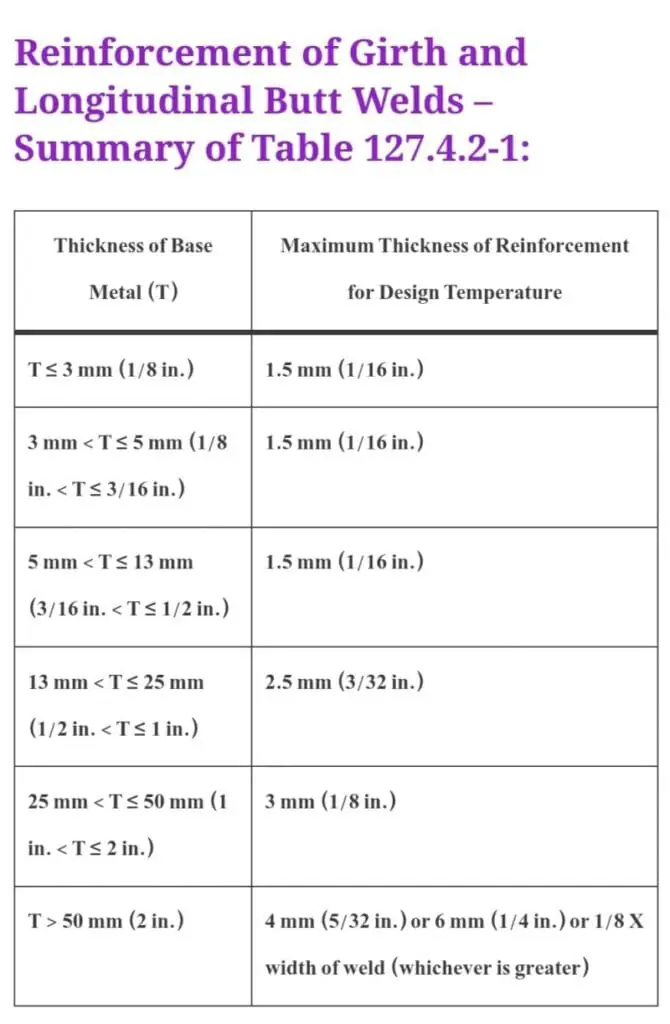
4. Weld Reinforcement Exceeding Specified Limits
Excessive weld reinforcement on butt joints creates a geometric stress concentration at the weld toes that accelerates fatigue crack initiation under cyclic thermal and pressure loading — exactly the loading pattern experienced by power piping. B31.1 therefore sets specific maximum reinforcement limits based on nominal pipe wall thickness:
| Nominal Wall Thickness | Maximum Weld Reinforcement (External) |
|---|---|
| Up to 6.4 mm (1/4 in.) | 1.6 mm (1/16 in.) |
| Over 6.4 mm (1/4 in.) to 12.7 mm (1/2 in.) | 3.2 mm (1/8 in.) |
| Over 12.7 mm (1/2 in.) to 25.4 mm (1 in.) | 4.0 mm (5/32 in.) |
| Over 25.4 mm (1 in.) | 4.8 mm (3/16 in.) |
Weld reinforcement is measured from the plane of the outer pipe surface to the highest point of the weld crown. A weld profile gauge or a straight edge with feeler gauges is used during VT to verify compliance. Weld reinforcement exceeding these limits must be ground down to an acceptable profile before the weld can be accepted. Grinding marks must be smooth and must not reduce the actual wall thickness below the minimum design thickness — verify with an ultrasonic thickness gauge after grinding.
5. Undercut — Circumferential Butt Welds
Acceptance limit: Maximum 0.8 mm (1/32 in.) depth AND must not encroach on minimum required section thickness.
Undercut is a groove or channel melted into the base metal at the weld toe during the welding process. It reduces the effective wall thickness at the most highly stressed location on the weld and creates a notch that concentrates stress under bending, pressure, and thermal loading. For circumferential butt welds in B31.1, undercut is permitted up to a maximum depth of 0.8 mm (1/32 in.), subject to the overriding condition that the remaining wall must meet the minimum required section thickness. Undercut depth is typically measured using a pit gauge or calibrated weld profile gauge.
6. Surface Undercut on Longitudinal Butt Welds
Acceptance limit: Zero. Any surface undercut on longitudinal seam welds is unacceptable.
B31.1 applies a more severe restriction to longitudinal welds than to circumferential welds. This distinction exists because longitudinal seams in power piping experience the full hoop stress from internal pressure — typically twice the axial stress from pressure alone — and any reduction in wall thickness at the seam toe directly reduces pressure-carrying capacity. The code therefore permits no undercut whatsoever on longitudinal butt welds, regardless of depth.
7. Linear Indications
Acceptance limit: Maximum 5 mm (3/16 in.) in length.
Linear indications include any surface-breaking feature with a length-to-width ratio greater than 3:1 — slag tracks, surface LOF seams, surface cracks too fine to clearly identify as cracks, or elongated porosity at the surface. Any linear indication greater than 5 mm (3/16 in.) in its longest dimension is unacceptable. Very short linear indications up to 5 mm may be conditionally accepted, but should be further investigated by PT to confirm they are not cracks, which are unconditionally rejected regardless of length.
8. Surface Porosity
Rejection conditions (either triggers rejection):
- Any single rounded indication with a maximum dimension greater than 5 mm (3/16 in.)
- A group of four or more rounded indications separated by 1.5 mm (1/16 in.) or less edge to edge in any direction
Surface porosity is evaluated as rounded indications — those with a length-to-width ratio of 3:1 or less. Individual small pores below 5 mm are accepted provided they do not occur in clusters of four or more at close spacing. The cluster criterion reflects the understanding that closely spaced pores act mechanically as a single larger defect due to ligament thinning between adjacent pores. Gas pores are typically caused by moisture contamination, shielding gas loss, or surface contaminants on the base metal. Persistent porosity during production welding warrants a weld process audit before additional joints are deposited.
9. Arc Strikes Outside the Weld Joint
Acceptance limit: Zero. Any arc strike outside the weld joint area is unacceptable.
An arc strike is a localised area where the welding arc has been initiated on or near the base metal surface outside the intended weld joint. Arc strikes create a small, rapidly quenched heat-affected zone in the base metal characterised by untempered martensite in carbon and low-alloy steels, or by sensitisation in austenitic stainless steels. In Cr-Mo power piping steels (such as P11, P22, P91, and P92), the hardened martensitic zone at an arc strike can initiate hydrogen cracking and, in service, fatigue cracks. All arc strikes must be ground out smooth, inspected by PT or MT, and if the remaining wall is within tolerance, the area may be accepted after NDE confirmation. If grinding reduces the wall below minimum, a repair weld or section replacement is required.
Quick Reference — B31.1 Visual Examination Rejection Summary
The following cards summarise every rejection criterion from Paragraph 136.4.2 at a glance. Use this grid as a field reference during visual examination.
any location = REJECT
= REJECT
accessible = REJECT
6.4–12.7t: 3.2 mm
12.7–25.4t: 4.0 mm
>25.4t: 4.8 mm
OR encroaches on min. wall = REJECT
undercut on longitudinal seams = REJECT
= REJECT
4+ pores within 1.5 mm edge-to-edge
outside weld joint = REJECT
B31.1 vs. B31.3 — Visual Acceptance Criteria Compared
Engineers and inspectors frequently work on projects that include both power piping under B31.1 and process piping under B31.3. Understanding where the two codes diverge is essential to avoid applying the wrong criterion — a common error that results either in unnecessary rework or, more seriously, in welds being accepted that should have been rejected under the applicable code.
| Discontinuity Type | ASME B31.1 (Power Piping) Para. 136.4.2 |
ASME B31.3 (Process Piping) Normal Fluid Service Table 341.3.2 |
Stricter Code |
|---|---|---|---|
| Cracks | Zero tolerance | Zero tolerance | Equal |
| Lack of Fusion (surface) | Zero tolerance | Zero tolerance | Equal |
| Incomplete Penetration | Zero (when ID accessible) | Limited ICP permitted (max 1-1/2 in. in any 6 in.) | B31.1 Stricter |
| Undercut — circumferential | max 0.8 mm (1/32 in.) | max 1.6 mm (1/16 in.) general; 0.8 mm for alloy steels | B31.1 Stricter |
| Undercut — longitudinal | Zero tolerance | Same max depth limits as circumferential apply | B31.1 Stricter |
| Weld Reinforcement | Tiered by wall thickness (1.6–4.8 mm) | Tiered by wall thickness (similar limits) | Broadly equivalent |
| Surface Porosity — single pore | max 5 mm (3/16 in.) | max 3 mm (1/8 in.) or t/4, whichever less | B31.3 Stricter (single pore) |
| Linear Indications | max 5 mm (3/16 in.) | max 5 mm (3/16 in.) | Equal |
| Arc Strikes | Zero tolerance outside weld joint | Zero tolerance | Equal |
Practical Guidance for B31.1 Visual Examination
Pre-Examination Preparation
Surface preparation before VT is not an optional step — it is a prerequisite for a valid examination. Wire brush all spatter from the weld surface and adjacent base metal within at least 25 mm of each weld toe. Remove slag (for SMAW and FCAW processes — less relevant for GTAW and GMAW) completely from the weld crown and toes using a chipping hammer followed by wire brushing. If the examination is performed after PWHT, remove all surface scale by brushing or light grinding. Do not grind the weld profile for cosmetic purposes before VT — if the weld crown appears oversized, measure it before grinding to document the as-deposited condition.
Lighting and Access
Position supplemental lighting at a low angle of incidence (raking light) across the weld surface to enhance the shadow contrast of surface discontinuities. Small, shallow undercut and fine surface cracks become far more visible under raking light than under diffuse overhead illumination. Use a weld profile gauge or straight edge to confirm reinforcement measurements rather than relying on visual estimation — gauges are inexpensive, quick to use, and produce a documentable measurement.
Documentation Requirements
While ASME B31.1 states that records of individual visual examinations are not always mandatory (except for in-process examination), sound quality practice dictates that VT results are recorded on the weld traveller or inspection record card for every weld. Record: weld identification number, examination date, examiner name and qualification, surface condition, any indications found and their disposition (accepted or rejected), and any corrective action taken. This record is required by most Quality Programmes operating under ASME and by power utility Owner requirements.
Repair Sequence for Rejected Welds
All rejected welds under B31.1 must follow a documented repair sequence before re-examination. The general sequence is: (1) map and document the location and character of each rejection, (2) identify the root cause before excavating (root cause determines the corrective action), (3) excavate by grinding, arc gouging, or machining to sound metal, extending 25 mm beyond the apparent limits of each discontinuity, (4) inspect the excavation by PT or MT to confirm removal to sound metal, (5) pre-heat if required by material and WPS, (6) re-weld using a qualified repair WPS, (7) perform PWHT if required, (8) re-examine by VT and any additionally required NDE method. For mechanical test requirements on production weld samples, see the WeldFabWorld mechanical testing guide.
NDE Methods Required in Addition to Visual Examination Under B31.1
Visual examination is the baseline but is not the sole NDE requirement for all B31.1 welds. Table 136.4 specifies when additional NDE is required. Passing VT does not guarantee that a weld is free of subsurface discontinuities — RT and UT are required for that assurance on welds meeting the pressure/temperature threshold.
| NDE Method | Standard | Scope in B31.1 | What It Detects (Beyond VT) |
|---|---|---|---|
| Radiographic Testing (RT) | ASME Section V Art. 2 | 100% for high-pressure/high-temp welds per Table 136.4 | Subsurface porosity, slag, LOP, LOF, cracks |
| Ultrasonic Testing (UT) | ASME Section V Art. 4/5 | Alternative to RT where geometry precludes RT; project-specified | Planar defects, LOF, cracks in thick sections |
| Liquid Penetrant (PT) | ASME Section V Art. 6 | Not required by B31.1 Table 136.4 alone; specified for PWHT verification, arc strikes | Surface and near-surface cracks, fine LOF seams |
| Magnetic Particle (MT) | ASME Section V Art. 7 | Ferromagnetic materials only; project-specified or as repair verification | Surface and near-surface cracks, sub-surface defects to ~3 mm depth |
For comprehensive guidance on all NDE methods applicable to power piping inspection, refer to the WeldFabWorld mechanical and non-destructive testing guide. For understanding how weld procedure and welder qualifications underpin the examination programme, the ASME Section IX practice quiz is an excellent self-assessment resource.
Recommended References for B31.1 Visual Examination
Disclosure: WeldFabWorld participates in the Amazon Associates programme (StoreID: neha0fe8-21). If you purchase through these links, we may earn a small commission at no extra cost to you. This helps support free technical content on this site.