Non-Destructive Testing (NDT):
A Complete Guide to Every Major Method
From a simple visual check to phased-array ultrasonics and radiographic film interpretation — NDT is the backbone of every quality assurance programme in welding and fabrication. This guide covers every major method: principles, step-by-step procedures, detection capabilities, applicable standards, and how to choose the right technique for your application.
NDT is mandated across industries including pressure vessel fabrication, pipeline construction, aerospace, power generation, bridges, and offshore structures. Standards such as ASME Section V (Article 1–26), AWS D1.1, API 650, and ISO 9712 govern how NDT must be performed, by whom, and to what acceptance criteria.
NDT vs Destructive Testing: Destructive tests (tensile, bend, Charpy impact, macro) provide definitive mechanical data but destroy the sample. NDT preserves the component while revealing surface, near-surface, and volumetric discontinuities. Both are used together in a comprehensive welding quality programme.
Visual Testing (VT)
Visual Testing is the examination of a component’s surface using the naked eye, with or without optical aids such as magnifying glasses, borescopes, mirrors, or remote video systems. It is always the first NDT method applied and is mandated by virtually every fabrication code before any other test proceeds. A component that fails visual examination is rejected without proceeding to costlier volumetric methods.
VT is governed by ASME Section V Article 9, AWS D1.1 Clause 6, and various other code-specific visual acceptance criteria. For pressure piping, ASME B31.1 specifies visual examination acceptance standards in detail.
What Does Visual Testing Detect?
Trained CWIs (Certified Welding Inspectors) and VT Level II technicians examine for the following welding defects:
- Cracks (surface-breaking — longitudinal, transverse, crater, toe)
- Incomplete fusion and lack of penetration (at the weld surface)
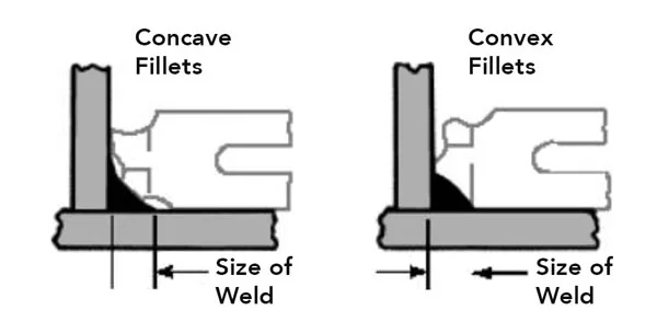
- Undercut — groove along weld toe reducing section thickness
- Overlap — weld metal overflowing onto base metal without fusion
- Porosity — surface-breaking gas voids (cluster, linear, piping)
- Inclusions — slag or other non-metallic material at the surface
- Excessive or insufficient weld reinforcement
- Burn-through, underfill, and spatter
- Surface contaminants — rust, mill scale, arc strikes adjacent to weld
- Dimensional non-conformances — weld size, leg length, throat
Important limitation: VT is restricted to surface-accessible and surface-breaking defects only. Subsurface flaws — embedded porosity, slag inclusions, lack of fusion below the surface — require volumetric NDT methods (RT or UT).
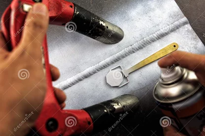
Dye Penetrant Testing (DPT / PT / LPT)
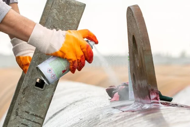
Dye Penetrant Testing (DPT), also called Liquid Penetrant Testing (LPT) or Penetrant Inspection (PI), exploits capillary action to draw a coloured or fluorescent liquid into surface-breaking discontinuities. After removal of excess penetrant, a developer draws the trapped liquid back to the surface, creating a visible indication against a contrasting background. DPT is applicable to all non-porous materials — metals, ceramics, plastics, and composites.
Governed by ASME Section V Article 6, AWS D1.1, and ASTM E165. Two major types: Color-Contrast (Visible) — red dye viewed under white light; and Fluorescent — viewed under UV (black) light for higher sensitivity.
Step-by-Step DPT Procedure
Sensitivity note: Fluorescent PT (FPT) is significantly more sensitive than visible-dye PT — it detects finer discontinuities. However, it requires a darkened area and UV lamp. For critical components (aerospace, nuclear), FPT is the preferred choice.
Radiographic Testing (RT)
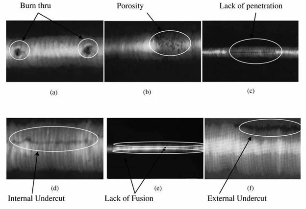
Radiographic Testing uses ionizing radiation — X-rays (from an X-ray tube) or gamma rays (from isotopes such as Ir-192, Se-75, Co-60, or Yb-169) — to penetrate a material and expose a radiographic film or digital detector on the opposite side. Variations in material density and thickness create differential absorption, producing a shadow-image that reveals internal discontinuities. RT produces a permanent visual record of the weld’s internal condition.
Governed by ASME Section V Article 2, ASME Section VIII UW-51/UW-52, AWS D1.1 Clause 8, and ISO 17636. Image quality is verified using Image Quality Indicators (IQIs) — wire type or hole type — placed on the source side to confirm adequate radiographic sensitivity.
RT Procedure Overview
Radiation Safety: RT involves ionizing radiation that is hazardous to personnel. Strict radiological safety controls are mandatory — exclusion zones, radiation surveys, dosimetry badges, and compliance with national regulatory requirements. Radiographers must be trained, certified, and authorized. Never approach a radiographic setup without confirming the source is secured.
RT vs UT for volumetric inspection: RT excels at detecting planar discontinuities oriented parallel to the beam (porosity, inclusions) and provides a permanent film record. UT is generally more sensitive to planar flaws (cracks, lack of fusion) regardless of orientation and has no radiation hazard. Many modern codes allow UT as an alternative to RT. Practice your RT knowledge with our Radiography Quiz.
🎯 Test Your NDT & Radiography Knowledge
Practice RT, inspection, and ASME code questions with our free online quizzes — used by thousands of welding and QA/QC professionals.
Ultrasonic Testing (UT)
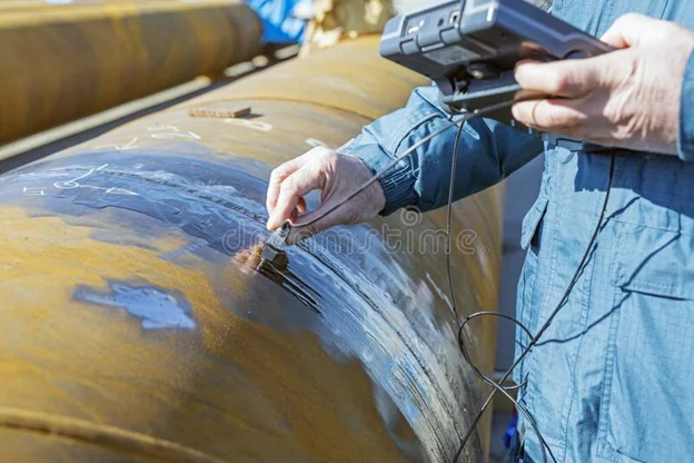
Ultrasonic Testing (UT) uses high-frequency sound waves (typically 0.5–25 MHz) generated by a piezoelectric transducer to interrogate the interior of a material. When a sound beam encounters a discontinuity or a back-wall boundary, some energy is reflected back to the transducer as an echo. The time of flight and amplitude of these echoes reveal the location, depth, and approximate size of internal flaws.
UT is widely regarded as the most sensitive and versatile volumetric NDT method. Modern variants include Phased Array UT (PAUT) — which steers and focuses multiple beams electronically — and Time-of-Flight Diffraction (TOFD), which provides highly accurate flaw sizing. Governed by ASME Section V Article 4, ASME VIII UW-53, AWS D1.1, and ISO 17640.
UT Procedure
PAUT advantage: Phased Array Ultrasonic Testing provides electronic beam steering, multiple angles simultaneously, and full weld volume coverage in a single pass. PAUT is increasingly replacing conventional RT in many pipeline and pressure vessel codes because it has no radiation hazard and detects planar flaws (cracks, lack of fusion) more reliably.
Magnetic Particle Inspection (MPI / MT)
Magnetic Particle Inspection (MPI), also called Magnetic Testing (MT), is applicable exclusively to ferromagnetic materials — iron, steel, nickel, and cobalt alloys. When a ferromagnetic component is magnetised, any discontinuity that disrupts the magnetic flux creates a localised leakage field at or near the surface. Ferromagnetic particles (dry powder or wet suspension) applied to the magnetised surface are attracted to and accumulate at these leakage field locations, forming visible indications.
MPI can detect defects up to approximately 3–6 mm below the surface (near-subsurface), making it more capable than PT for near-surface flaws but restricted to magnetic materials. Governed by ASME Section V Article 7, ASTM E709, and ISO 17638. For the complete procedure and equipment details, see our dedicated article: Magnetic Particle Inspection (MPI) — Complete Guide.
MPI Four-Step Process
Magnetisation direction matters: A defect is best detected when the flux is perpendicular to its longest dimension. To ensure full coverage, magnetisation must be applied in at least two perpendicular directions. A crack parallel to the field direction will not create a leakage field and will be missed.
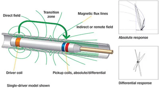
Electromagnetic / Eddy Current Testing (ECT / ET)
Eddy Current Testing (ECT) uses electromagnetic induction to detect surface and near-surface flaws in electrically conductive materials. An AC-driven coil generates an alternating magnetic field; when brought near a conductor, it induces circulating electrical currents (eddy currents) within the material. Discontinuities, cracks, or variations in material properties disrupt these eddy currents, producing measurable changes in coil impedance that a receiver circuit detects and displays.
ECT is particularly valuable for heat exchanger tube inspection — detecting wall thinning, pitting, cracking, and corrosion inside tubes without requiring the tube to be filled with liquid. It is also widely used for detecting surface cracks in aerospace components and weld toe cracks in structural applications. Governed by ASME Section V Article 8 and ASTM E213/E309/E426.
Key Advantages of ECT
- No couplant required — non-contact technique (probe is placed near surface)
- High-speed scanning capability — suitable for automated in-service inspection of tube banks
- Sensitive to surface and near-surface defects including tight fatigue cracks
- Can simultaneously measure conductivity and permeability variations (alloy sorting, heat treatment verification)
- Signal can be complex — requires experienced interpreter to distinguish relevant indications from lift-off noise and edge effects
ECT in heat exchanger inspection: ECT is the standard technique for in-service inspection of heat exchanger tubes per ASME, TEMA, and API guidelines. It detects internal pitting, stress corrosion cracking, and erosion thinning — enabling condition assessment without removing the tube bundle from service.
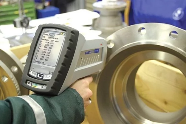
Positive Material Identification (PMI)
PMI is an NDT technique used to verify and confirm the chemical composition of materials — base metals, filler metals, and weld deposits — ensuring they match the specified requirements. In industries such as oil & gas, petrochemical, power, and nuclear, the use of incorrect materials can lead to catastrophic service failures (corrosion, cracking, loss of mechanical properties). PMI is mandatory on critical piping and pressure vessel systems in many facilities.
Two primary handheld technologies are used:
- X-Ray Fluorescence (XRF): Bombards the surface with X-rays, causing characteristic secondary X-ray emission from elements in the material. Provides fast, accurate elemental analysis (except for light elements C, N, O, and B). Most widely used PMI technique.
- Optical Emission Spectroscopy (OES) / Spark Spectroscopy: Uses a spark discharge to vaporise a small amount of surface material; the emitted light spectrum identifies elements including carbon. More accurate than XRF for carbon content — critical for carbon steel vs. stainless steel mix-ups.
When Is PMI Mandatory?
- Alloy piping and pressure vessels in sour service, high-temperature, or corrosive service
- Stainless steel, chrome-moly, duplex SS, nickel alloy, and titanium components
- Any material where heat number traceability is lost or material test certificates (MTC) are unavailable — see our guide on how to read a Material Test Certificate
- Weld deposits on P91/P92 and other high-alloy systems to verify Cr, Mo, V, Nb content
- Per API 578 (Material Verification Programme) as part of process safety management
Critical industry case: Several major refinery and plant failures have been caused by the inadvertent use of carbon steel components in alloy service lines due to material mix-ups. PMI programmes prevent these substitution errors before they enter service.
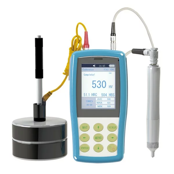
Hardness Testing
Hardness testing measures a material’s resistance to permanent deformation under an applied load. In welding and fabrication, hardness is particularly important for: verifying PWHT effectiveness, confirming compliance with sour service hardness limits (typically ≤ 250 HV10 / 22 HRC for NACE MR0175), assessing heat-affected zone properties, and evaluating the success of procedure qualification tests.
Major Hardness Test Methods
| Method | Indenter | Scale / Unit | Best Used For |
|---|---|---|---|
| Rockwell | Diamond cone (HRC) or ball (HRB) | HRC, HRB | Fast shop-floor testing; sour service compliance checks |
| Vickers (HV) | Square-pyramid diamond | HV (e.g., HV10) | Weld procedure qualification; HAZ surveys; thin materials |
| Brinell (BHN) | Hardened steel or WC ball | BHN / HBW | Castings, forgings, rough surfaces; large indentation area |
| Knoop | Rhombic pyramid diamond | HK | Brittle materials, thin coatings, microhardness mapping |
| Shore / Durometer | Sharp cone | Shore A/D | Polymers, elastomers, soft materials only |
Sour service hardness limit: Per NACE MR0175/ISO 15156, the maximum permitted hardness in weld metal and HAZ for low-alloy and carbon steels in sour service is 250 HV10 (≈ 22 HRC). Exceeding this limit significantly increases risk of Sulphide Stress Cracking (SSC). Vickers HV10 is the preferred measurement scale for weld qualification testing. See also our article on Sour Service requirements.
NDT Methods — Side-by-Side Comparison
| Method | Flaw Location | Ferrous | Non-Ferrous | Permanent Record | Radiation Hazard | Skill Level | Relative Cost |
|---|---|---|---|---|---|---|---|
| VT — Visual | Surface only | ✔ | ✔ | Photo only | None | Level II CWI | Low |
| DPT — Penetrant | Surface-breaking | ✔ | ✔ | Photo | None | PT Level II | Low |
| RT — Radiography | Surface + Volumetric | ✔ | ✔ | Film / Digital | X-ray / γ-ray | RT Level II | Medium–High |
| UT — Ultrasonic | Surface + Volumetric | ✔ | ✔ | Encoded scan | None | UT Level II | Medium |
| MPI — Magnetic Particle | Surface + Near-surface | ✔ | ✘ Not applicable | Photo | None | MT Level II | Low–Medium |
| ECT — Eddy Current | Surface + Near-surface | ✔ | ✔ | Signal data | None | ET Level II | Medium |
| PMI | Composition (surface) | ✔ | ✔ | Digital report | Low (XRF) | Trained operator | Low–Medium |
| Hardness Testing | Surface / cross-section | ✔ | ✔ | Numeric values | None | Trained operator | Low |
How to Choose the Right NDT Method
The correct NDT method — or combination of methods — is determined by the material, weld type, defect orientation, code requirement, and whether surface or volumetric coverage is needed. Use this guide as a starting point:
🔍 Surface Cracks Only
- Ferrous materials → MPI (most sensitive)
- Non-ferrous (SS, Al, Ti) → DPT
- Both → DPT as backup to MPI
- Complex geometry / weld toes → Fluorescent PT or MT
🌊 Volumetric (Internal) Defects
- Permanent film record required → RT
- Thick section / no radiation → UT
- Planar flaws (cracks, LOF) → UT / PAUT preferred over RT
- Porosity / slag → RT excellent; UT also capable
🏭 In-Service / Maintenance
- Heat exchanger tubes → ECT
- Pipe wall thickness → UT (straight beam)
- Crack detection in service → MPI or PAUT
- Risk-based inspection → see API 580 RBI
🔬 Material Verification
- Alloy confirmation → PMI (XRF)
- Carbon content confirmation → OES / spark
- PWHT and sour service → Hardness (HV10)
- Lost MTC traceability → PMI mandatory
Advantages of Non-Destructive Testing
🎯 Ready to Test Your NDT Knowledge?
Practice with our free quizzes — Radiography, ASME Section IX, API 580 RBI, and AWS/CSWIP exam prep, all in one place.