Welding Defects — Types, Causes & Remedies: Complete Technical Guide
Welding defects are the leading cause of weld rejections, costly repairs, and — in the worst cases — catastrophic structural failures in pressure vessels, pipelines, and load-bearing structures. Every welder, welding inspector, and fabrication engineer must have a working knowledge of the eight most common welding defect types: what they look like, what causes them, how they are detected, and how to prevent them. This guide covers all of that in a single, comprehensive technical reference.
A key distinction that underpins all weld quality work is the difference between a discontinuity and a defect. Not every imperfection in a weld is a defect — classification depends entirely on the applicable acceptance criteria in the governing code (AWS D1.1, ASME Section VIII, API 1104, etc.). Understanding this boundary is the foundation of professional weld quality work.
This article covers all eight of the most commonly encountered weld discontinuities in arc welding, with detailed causes-and-remedies tables, SVG cross-section diagrams, original photographs, and practical inspection notes drawn from real fabrication and code inspection experience. For related quality work, see our article on the welding inspection checklist and our guide to mechanical testing requirements per ASME Section IX.
What is a Weld Defect? Definitions and Scope
The AWS and ASME codes provide precise, code-compliant definitions that every inspection professional must use correctly:
| Term | Definition | Code Reference |
|---|---|---|
| Discontinuity | An interruption in the normal physical structure or configuration of a weld. May or may not be rejectable. | AWS A3.0 |
| Defect | A discontinuity or discontinuities that, by nature or accumulated effect, render a weld unable to meet the minimum applicable acceptance standards or specifications. | AWS A3.0 |
| Flaw | An undesirable discontinuity; used informally to mean any imperfection in the weld. | General usage |
| Imperfection | Departure of a quality characteristic from its intended level; preferred term in ISO standards (ISO 6520). | ISO 6520-1 |
When a discontinuity is found during inspection, the inspector must compare its measured characteristics (depth, length, area, orientation) against the acceptance criteria table in the governing standard. Only when those criteria are exceeded is the discontinuity classified as a defect requiring repair or rejection.
Classification of Weld Discontinuities
It is useful to understand both the location and geometric character of a discontinuity before selecting an NDT method for detection. The table below summarises the eight defect types covered in this guide alongside their primary detection methods and code-rejectable criteria basis.
| # | Defect Name | Type | Location | Primary NDT | Zero Tolerance? |
|---|---|---|---|---|---|
| 1 | Burn-Through | Surface | Root / face | VT | Yes (most codes) |
| 2 | Lack of Penetration (LOP) | Planar | Root | RT, UT | Depends on code |
| 3 | Lack of Fusion (LOF) | Planar | Fusion face / inter-pass | UT, RT | Yes (most codes) |
| 4 | Slag/Tungsten Inclusions | Volumetric | Inter-pass / surface | RT, UT | No — size/density limited |
| 5 | Cracks | Planar | Any | MT, PT, UT, RT | Yes — zero tolerance |
| 6 | Porosity | Volumetric | Any | RT, UT, VT (surface) | No — size/density limited |
| 7 | Overlap | Surface | Weld toe / root | VT, PT, MT | Yes (AWS D1.1) |
| 8 | Undercut | Surface | Weld toe | VT (pit gauge) | No — depth limited |
Eight Common Welding Defects
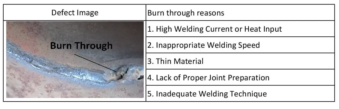
Burn-Through
Burn-through occurs when excessive heat input melts completely through the base material at the root of the joint, forming a hole or a thin, sunken area in the weld. It is characterised by a visible hole or a concave depression at the root that has breached the original material surface. In pressure vessel and piping fabrication, burn-through is almost always rejectable because it compromises the pressure-containing boundary of the joint.
Causes and Remedies
| Cause | Remedy |
|---|---|
| Excessive welding current for the material thickness | Reduce amperage; use the correct current range for the electrode diameter and material thickness |
| Too-slow travel speed — arc dwells too long in one spot | Increase travel speed to reduce heat input per unit length |
| Excessively wide root gap or thin root face | Tighten the root gap to within the WPS limits; increase root face dimension |
| Incorrect welding position (e.g., overhead without technique adjustment) | Adjust technique: use a slightly higher travel speed and weaving technique to avoid pooling |
| Material too thin for the process selected | Switch to a lower-heat process (TIG/GTAW) or use backing bars to control melt-through |
| Pulsed current not set correctly for thin material | Use pulsed GMAW or GTAW with appropriate peak/background current settings |
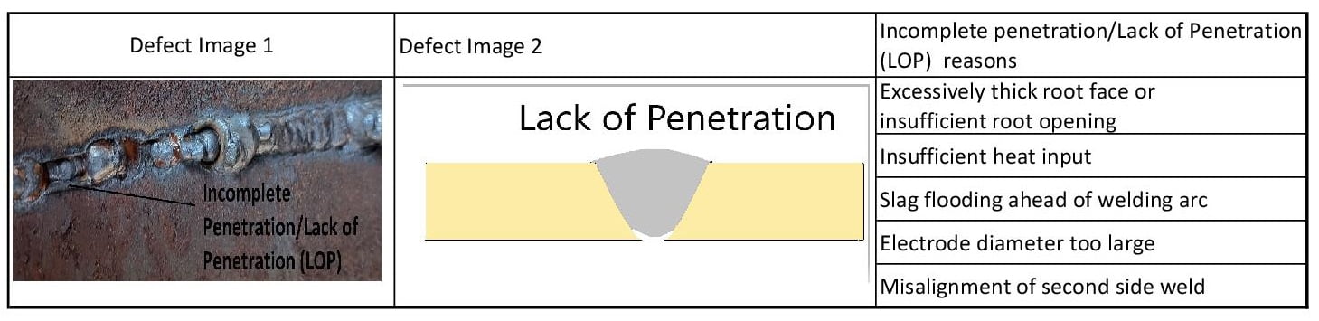
Incomplete Penetration / Lack of Penetration (LOP)
The AWS definition states: “A joint root condition in a groove weld in which weld metal does not extend through the joint thickness.” In practice, LOP means the weld bead has not reached the root of the joint — leaving an unfused gap at the bottom of the groove. Because LOP creates a planar, notch-like defect at the highest-stress region of the joint (the root in tension loading), it significantly reduces fatigue life and is rejectable under most structural and pressure vessel codes.
Causes and Remedies
| Cause | Remedy |
|---|---|
| Insufficient heat input — current too low | Increase welding current within WPS qualified range; ensure proper amperage for electrode diameter |
| Excessive travel speed — arc moves forward before penetrating | Reduce travel speed to allow sufficient melt-through at the root |
| Root gap too narrow for process to access | Increase root gap to minimum specified in WPS; ensure joint fit-up is within tolerance |
| Root face too thick (land too large) | Reduce root face dimension so heat can reach through the joint |
| Electrode too large for the joint access | Use a smaller diameter electrode for the root pass, then upsize for fill and cap passes |
| Poor joint preparation — groove angle too tight | Increase groove angle to ensure adequate arc access to the root; follow WPS requirements |
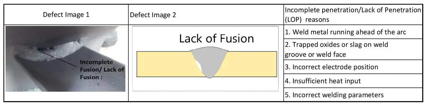
Incomplete Fusion / Lack of Fusion (LOF)
Lack of Fusion (LOF) occurs when the weld metal fails to fuse with the base metal at the groove faces, or when successive weld passes fail to fuse with the previously deposited bead. Unlike LOP (which occurs specifically at the root), LOF can occur anywhere along the fusion line. The AWS code defines it as: “A weld discontinuity in which fusion did not occur between weld metal and fusion faces or adjoining weld beads.”
LOF is a planar defect and is universally rejectable under ASME, AWS, and API codes. Its detection requires volumetric NDT — UT (especially phased array UT) is the most reliable method because its planar orientation can give weak or no indication by RT if the beam is not directed perpendicular to the defect plane.
Causes and Remedies
| Cause | Remedy |
|---|---|
| Low heat input — arc energy insufficient to melt groove faces | Increase amperage and/or reduce travel speed; ensure WPS heat input range is followed |
| Incorrect torch/electrode angle — arc not directed at the fusion face | Direct the arc toward the fusion face, not just into the weld pool; adjust work angle |
| Excessive travel speed — pool does not wet the groove walls | Reduce travel speed; use weave technique to drive the arc into each groove face |
| Contamination on groove faces (mill scale, paint, oil, moisture) | Clean all groove surfaces before welding; grind or wire-brush to bare metal |
| Inter-pass slag or oxide not cleaned between passes | Thoroughly wire-brush and chip slag between every pass; use a grinder where necessary |
| Excessive joint volume — large gap or thick joint requires multiple passes | Follow the multi-pass WPS sequence; do not attempt to fill too much in one pass |
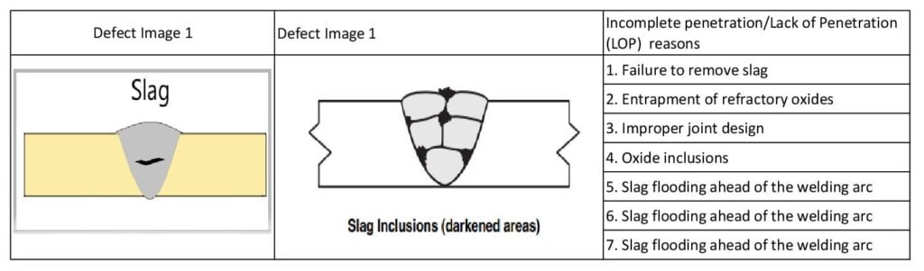
Inclusions (Slag and Tungsten)
The AWS code defines inclusions as: “Entrapped foreign solid material, such as slag, flux, tungsten, or oxide.” Two distinct types are important in arc welding practice:
- Slag inclusions — solid flux residue trapped in the weld metal, most common in SMAW, FCAW, and SAW. They form when slag from one pass is not fully removed before depositing the next pass, or when welder technique allows slag to run ahead of the arc.
- Tungsten inclusions — fragments of tungsten electrode material trapped in the weld metal, exclusive to GTAW (TIG welding). They form when the electrode contacts the weld pool or filler wire, causing particle transfer into the molten metal.
Causes and Remedies — Slag Inclusions
| Cause | Remedy |
|---|---|
| Failure to remove inter-pass slag completely | Wire-brush and chip thoroughly between every weld pass; use needle scaler for tight areas |
| Slag running ahead of the arc (wrong electrode angle) | Maintain a leading electrode angle (drag technique for SMAW) to keep slag behind the arc |
| Undercutting on previous pass trapping slag | Correct the undercut before depositing the next pass; grind or blend the undercut area |
| Weld joint too narrow for slag to escape | Increase groove angle; use a narrower electrode; ensure adequate root opening |
| Wrong polarity or incorrect current type for electrode | Use the correct polarity and current range as specified by the electrode manufacturer |
Causes and Remedies — Tungsten Inclusions (GTAW)
| Cause | Remedy |
|---|---|
| Contact between tungsten electrode and weld pool | Maintain proper arc length (1–3 mm); avoid dipping the electrode into the pool |
| Contact between electrode and filler wire | Control filler wire feed angle; avoid the wire touching the electrode tip |
| Current exceeding the electrode’s capacity — tip melts | Use the correct electrode diameter for the current range; do not exceed maximum current rating |
| Contaminated electrode tip — used wrong polarity | Re-grind the electrode to remove contamination; use correct polarity (DCEN for steel/stainless) |
Weld Cracks
The AWS definition: “A fracture-type discontinuity characterised by a sharp tip and a high ratio of length and width to opening displacement.” Cracks are the most severe weld discontinuity class because their geometry — a sharp tip — creates extreme stress concentration under load, and cracks have a strong tendency to propagate. Virtually all applicable welding codes impose zero tolerance for cracks regardless of size.
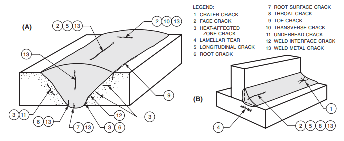
Types of Weld Cracks
Cracks are classified by location, orientation, and the metallurgical mechanism that caused them. The most clinically important crack types in fabrication are:
| Crack Type | Mechanism | When it Occurs | Susceptible Materials |
|---|---|---|---|
| Hot Crack / Solidification Crack | Segregation of low-melting constituents (S, P) to grain boundaries during weld metal solidification | During or immediately after welding | Austenitic stainless steels, high-carbon steels, aluminium alloys |
| Hydrogen-Induced Cold Crack (HICC) | Diffusible hydrogen trapped in hard (martensitic) HAZ microstructure under residual stress | Hours to days after welding (delayed) | C-Mn steels, low-alloy steels with CE > 0.40 |
| Lamellar Tear | Fracture of MnS or oxide stringers in base metal under through-thickness shrinkage stress | During welding — cooling contraction | Rolled steels with sulphur inclusions; tee joints, cruciform joints |
| Reheat Crack / SR Crack | Grain boundary embrittlement during post-weld heat treatment in creep-resistant alloys | During PWHT | Cr-Mo steels (P11, P22, P91); nickel alloys |
| Crater Crack | Solidification shrinkage in the weld crater when the arc is abruptly stopped | At arc termination | Any material — technique-related |
| Stress Corrosion Crack (SCC) | Combined action of tensile stress and corrosive environment | In-service | Austenitic stainless in chloride environments; duplex stainless |
For an in-depth treatment of hot cracking mechanisms and prevention, see our dedicated guide on hot cracking in welds. For materials particularly susceptible to HICC, the carbon equivalent calculator is essential for determining preheat requirements.
Causes and Remedies — Weld Metal Cracking
| Cause | Remedy |
|---|---|
| Highly restrained joint — high residual stress | Apply preheat; use backstep or block welding sequence to reduce restraint; consider post-weld stress relief |
| Defective or wet electrodes (hydrogen source) | Bake SMAW electrodes per manufacturer’s recommendations (typically 300–350°C for 1–2 hr); use low-hydrogen consumables |
| Small, concave bead cross-section — insufficient weld metal to resist shrinkage | Use a slightly convex bead profile; do not allow crater to be underfilled; use a larger electrode or slower travel |
| High sulphur base metal — hot cracking via FeS segregation | Use filler metals with low sulphur content; consider buttering with a compatible low-sulphur filler |
| Crater cracking — arc stopped abruptly | Fill the crater before stopping; use the backfill technique or a current decay device |
Causes and Remedies — HAZ Cracking
| Cause | Remedy |
|---|---|
| Hydrogen in welding atmosphere — HICC | Use low-hydrogen process; preheat and hold at minimum 100°C; apply post-weld hydrogen release heat treatment (250°C, 2–4 hr) before PWHT |
| High carbon equivalent (CE) — high hardenability | Preheat based on CE calculation; increase heat input; avoid rapid cooling; consider PWHT immediately after welding |
| High residual stresses in restrained joint | Redesign joint geometry; change welding sequence to balance shrinkage; apply intermediate PWHT |
| Low base metal ductility (as-rolled or hardened condition) | Anneal or normalise base metal before welding; apply preheat |
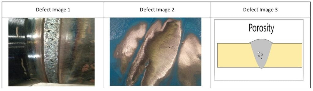
Porosity
The AWS definition: “Cavity-type discontinuities formed by gas entrapment during solidification or in a thermal spray deposit.” Porosity forms when gas is trapped in the solidifying weld pool. The gas can originate from contamination on the workpiece or filler metal, atmospheric contamination due to inadequate shielding, or from chemical reactions within the weld pool itself.
Porosity is classified by its distribution pattern, which itself provides diagnostic clues about the cause:
- Uniformly scattered porosity — gas distributed throughout the weld; typically caused by contamination or shielding issues
- Clustered porosity — concentrated in one area; often linked to a local contamination source or an arc restart
- Piping porosity (wormholes) — elongated gas channels aligned roughly perpendicular to the weld surface; typically caused by excessive moisture, especially in SAW or SMAW
- Linear porosity — aligned along the weld axis; can be confused with LOF on RT; usually related to inter-pass contamination
Causes and Remedies
| Cause | Remedy |
|---|---|
| Insufficient shielding gas coverage — hydrogen/nitrogen/oxygen contamination of weld pool | Increase shielding gas flow rate; check for drafts or air entrainment; inspect hoses and connections for leaks |
| Contaminated base metal — oil, grease, paint, moisture, mill scale | Clean the joint thoroughly before welding — degrease with acetone or equivalent; grind to bare metal; preheat to drive off moisture |
| Contaminated filler wire — drawing compounds, moisture on wire surface | Use specially cleaned and packaged filler wire; store in dry conditions; reject wire that has been left exposed |
| Wet or moisture-absorbed SMAW electrodes | Bake electrodes per manufacturer’s schedule; store in heated oven after opening |
| Excessive arc length — atmosphere contact with the pool | Maintain the correct arc length for the electrode diameter — approximately equal to electrode core diameter |
| High solidification rate — gas cannot escape before pool freezes | Apply preheat to slow the cooling rate; increase heat input within WPS range |
| Galvanised steel — zinc vapourisation at weld pool | Remove zinc coating from the weld area before welding; alternatively use E6010 electrodes with a zinc-ahead technique |
| High sulphur base metal — CO/CO2 gas generation | Use electrodes with basic slag system (high deoxidiser content) that can fix sulphur in slag |
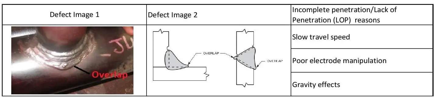
Overlap
The AWS definition: “The protrusion of weld metal beyond the weld toe or weld root.” Overlap occurs when molten weld metal flows beyond the fusion line and lays on top of the base metal without fusing with it. The resulting notch at the weld toe — where the unfused overlap meets the base metal — acts as a stress raiser and a potential fatigue crack initiation site. Overlap is rejectable under AWS D1.1 and most structural codes.
Causes and Remedies
| Cause | Remedy |
|---|---|
| Excessive current — too much molten metal generated for the travel speed | Reduce amperage; balance with travel speed to avoid over-depositing |
| Too-slow travel speed — metal piles up ahead of the arc | Increase travel speed; maintain a consistent bead width |
| Incorrect electrode angle — metal directed toward base metal surface rather than into joint | Adjust work and travel angle to direct the arc into the weld pool; avoid a steep pushing angle |
| Insufficient base metal preheat — cold base metal causes rapid solidification at the toe | Apply interpass temperature control; maintain minimum preheat per WPS |
| Excessive weaving — over-wide bead deposits weld metal beyond the fusion zone | Limit weave width to 2.5x electrode diameter; use stringer beads for out-of-position welding |
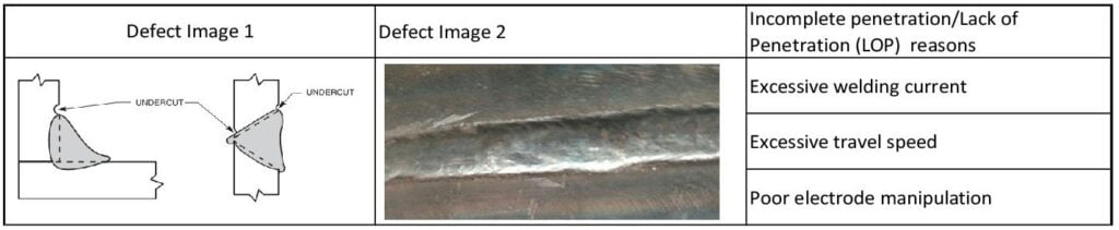
Undercut
The AWS definition: “A groove melted into the base metal adjacent to the weld toe or weld face and left unfilled by weld metal.” Undercut is one of the most frequently encountered surface defects in arc welding. The groove formed at the weld toe reduces the effective cross-section of the base metal and introduces a sharp notch that is particularly damaging under cyclic (fatigue) loading. Detection by visual testing is straightforward — the groove is visible to the naked eye under oblique lighting.
Causes and Remedies
| Cause | Remedy |
|---|---|
| Excessive welding current | Reduce amperage; check current against WPS range for the electrode/wire diameter |
| Excessive arc length — arc erodes the groove face | Maintain a short, consistent arc length; for SMAW, arc length should equal electrode core diameter |
| Incorrect electrode angle — arc directed away from the fill zone | Adjust the work angle to direct the arc back into the molten pool and fill the toe region |
| Excessive travel speed — insufficient metal to fill the toe | Reduce travel speed; pause briefly at the weld toes during weaving |
| Incorrect weaving technique — excessive dwell in the centre, not at the toes | Pause at each toe during weave; this directs filler metal to fill the eroded groove |
| Wrong shielding gas mixture for GMAW — argon-rich mixes reduce undercut vs. CO2 | Use Ar-CO2 blends (75/25 or 80/20) rather than 100% CO2 for reduced spatter and better bead profile |
NDT Detection Methods for Weld Defects
Selecting the correct Non-Destructive Testing (NDT) method is essential — using the wrong technique means defects will be missed even when the inspection is performed correctly. The table below summarises the applicability of each major method to the eight defect types covered above.
| NDT Method | Abbreviation | Defects Detected | Limitations |
|---|---|---|---|
| Visual Testing | VT | Undercut, overlap, burn-through, surface porosity, surface cracks, spatter, dimensional check | Surface-only; requires good lighting and access; cannot detect subsurface defects |
| Liquid Penetrant Testing | PT / LPT | Surface-breaking cracks, surface porosity, surface LOF | Surface-only; not effective on rough surfaces; requires clean, non-porous base |
| Magnetic Particle Testing | MT / MPI | Surface and near-surface cracks, LOF, LOP (near surface) | Ferromagnetic materials only (steel); not applicable to austenitic SS or aluminium |
| Radiographic Testing | RT | Porosity, slag/tungsten inclusions, LOP, LOF (some), cracks (if aligned with beam) | Planar defects parallel to the beam may not be detected; radiation safety requirements; slow |
| Ultrasonic Testing | UT / PAUT | All subsurface defects including LOF, LOP, cracks, inclusions, lamellar tears | Requires skilled operator; rough surfaces cause noise; less effective on thin sections (<8 mm) |
| Phased Array UT | PAUT | All UT defects plus improved detection of planar defects at various orientations; sizing capability | Higher equipment cost; requires qualified setup; complex for field use |
For more detailed guidance on NDT qualification and procedure requirements, refer to the welding inspection checklist and the mechanical testing requirements per ASME Section IX.
Prevention Through Process Control
The majority of welding defects are preventable through disciplined process control and quality assurance at every stage of the fabrication sequence. The following areas have the greatest impact on defect prevention:
1. Welding Procedure Specification (WPS) Compliance
Every weld must be made to a qualified and approved WPS. The WPS defines the essential variables — base metal, filler metal, preheat, interpass temperature, heat input range, travel speed, position, and PWHT — that were qualified during the procedure qualification record (PQR) testing. Drifting outside WPS parameters is the primary cause of preventable defects in the fabrication shop. For P-number and group number classification relevant to your WPS, see our P-Number and F-Number guide.
2. Material and Consumable Control
Electrode and filler wire condition directly affects porosity, cracking, and inclusion rates. Establish and enforce a written consumable control procedure that covers receipt inspection, storage conditions, baking and re-drying schedules, and rejection criteria for damaged packaging. For low-hydrogen SMAW electrodes, bake at 300–350°C for 1–2 hours and store in a heated electrode oven at 65–120°C. See our guide on welding consumable nomenclature for classification guidance.
3. Joint Fit-Up and Preparation
Poor joint fit-up — excessive root gap, out-of-tolerance root face, insufficient groove angle — makes it impossible for the welder to produce a defect-free root regardless of skill level. Dimensional checks before welding (in-process inspection) catch these issues before they become expensive repairs. Ensure all joint dimensions are within the WPS and engineering drawing tolerances.
4. Preheat and Interpass Temperature
Preheat prevents hydrogen-induced cold cracking (HICC) by slowing the cooling rate, reducing hydrogen diffusion rate, and reducing the hardness of the HAZ microstructure. Interpass temperature control prevents both overheating (which can degrade HAZ toughness and cause hot cracking) and undercooling (which allows hydrogen to accumulate). For carbon equivalent-based preheat determination, use the CE calculator.
5. Welder Qualification and Skill
Many defects — undercut, overlap, porosity, and LOF in particular — are fundamentally technique-related. Ensure all welders are qualified per the applicable code (ASME Section IX, AWS D1.1, etc.) for the positions, processes, and materials they are welding. Maintain welder continuity records and reinstate qualification when continuity is broken. For qualification range details, review the mechanical testing requirements per ASME Section IX.
Recommended Reference Books
The following technical references are essential reading for anyone working in welding inspection, quality assurance, or fabrication engineering. All are available via Amazon India.
Disclosure: WeldFabWorld participates in the Amazon Associates programme (StoreID: neha0fe8-21). If you purchase through these links, we may earn a small commission at no extra cost to you. This helps support free technical content on this site.