Welding Porosity — Causes, Types, Prevention and Repair: Complete Technical Guide
Welding porosity — cavity-type discontinuities formed by gas entrapment during weld pool solidification — is one of the most frequently encountered weld defects across every welding process and industry sector. Whether you are working with SMAW on structural carbon steel, MIG welding aluminium, or TIG welding stainless pressure piping, porosity has the same root mechanism: gas bubbles generated or drawn into the weld pool that cannot escape before the metal solidifies around them.
The consequences range from minor cosmetic blemishes that fall within code acceptance limits, to structurally significant defects that reduce the load-carrying cross-section of the weld, create notch points under fatigue loading, and in subsurface form act as initiation sites for hydrogen-assisted cracking in high-strength steels. Understanding every aspect of porosity — how it forms, how it is classified, how each process is vulnerable, and how codes judge it — is a fundamental competency for welders, welding engineers, and CWI/CSWIP inspectors alike.
This guide covers the complete picture: the physics of gas entrapment, all morphological types, causes broken down by welding process, a quantitative prevention framework, acceptance criteria per AWS D1.1 and ASME, and a structured repair procedure. Internal links throughout direct you to related technical resources on WeldFabWorld.
Definition and Metallurgical Mechanism
The American Welding Society defines porosity as “cavity-type discontinuities formed by gas entrapment during solidification or in a thermal spray deposit.” In practical terms, porosity represents locations within the solidified weld metal where a gas bubble was present at the moment the surrounding metal froze.
The mechanism operates in two stages. First, a gas-generating event occurs in or around the weld pool — decomposition of moisture, vaporisation of hydrocarbons, pick-up of atmospheric nitrogen or oxygen, or outgassing from dissolved hydrogen in the parent metal. Second, the bubble must fail to escape the pool before the solidification front catches up with it. Whether it escapes depends on the balance between buoyancy, pool viscosity, surface tension, and the speed of the solidification front.
Gas Sources in the Weld Pool
Four gases are responsible for virtually all porosity encountered in fusion welding:
- Hydrogen (H): Generated from moisture, hydrocarbons, or organic coatings. Extremely high solubility in liquid iron, near-zero solubility in solid iron — precipitation on freezing creates round pores and contributes to hydrogen-assisted cold cracking.
- Nitrogen (N): Absorbed from air when shielding is lost. Produces elongated or wormhole-type porosity; associated with surface roughness. More common in FCAW and GMAW than in SMAW.
- Oxygen (O): Less commonly a sole cause; reacts with carbon in the pool to form CO bubbles, particularly problematic when welding high-carbon or undeoxidised steels.
- Carbon monoxide (CO): Forms when dissolved carbon reacts with oxygen in the pool. Round pores; most common in cast iron welding and in processes with insufficient deoxidants in the filler.
Types of Porosity in Welding
Porosity is classified by morphology (shape and distribution), which directly informs the probable cause and determines the radiographic appearance used for acceptance evaluation.
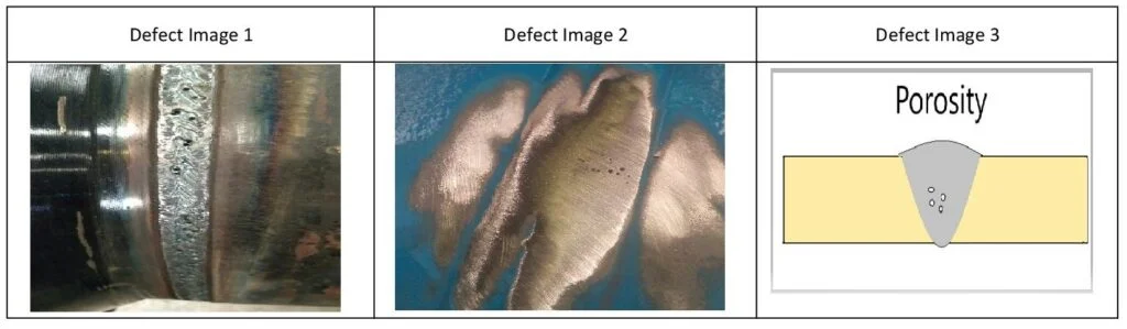
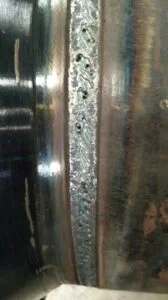
1. Surface Porosity (Open Pores)
Surface porosity breaks through the weld face and is visible to the naked eye or under low-power optical magnification. The pores often appear distributed along the weld bead in a swiss-cheese pattern and may be concentrated at the bead start, crater, or along the centreline. Surface-breaking pores are generally less acceptable than subsurface pores under most codes because they are directly exposed to the service environment and can initiate pitting corrosion.
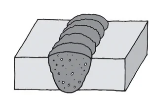
2. Subsurface (Internal) Porosity
Subsurface porosity is fully enclosed within the weld metal and can only be detected by volumetric non-destructive examination (NDE) — primarily radiographic testing (RT) or ultrasonic testing (UT). On a radiograph, isolated subsurface pores appear as rounded dark spots; clustered porosity appears as a group of dark spots; and linear porosity appears as a row of spots aligned along the weld axis.
3. Clustered (Grouped) Porosity
A local concentration of pores in one area, typically at weld starts where the arc is cold, at stop/restart locations, or where a sudden contamination event occurred. Clustered porosity is assessed as an aggregate area on radiographs and is subject to stricter limits than isolated pores of equivalent individual diameter.
4. Linear Porosity
Pores aligned in a row, usually along the weld centreline or fusion line. Linear porosity often indicates a consistent but intermittent problem — recurring gas release from a seam contaminant, a momentary shielding interruption, or a repeating parametric variation. AWS D1.1 evaluates linear porosity by the sum of diameters in any 25 mm (1 in) length of weld.
5. Wormhole Porosity (Piping / Elongated Porosity)
Elongated, tubular cavities oriented roughly perpendicular or at an acute angle to the weld axis. On a radiograph, multiple wormholes create a characteristic herringbone or fishbone pattern. Wormhole porosity is the most severe morphological form and almost invariably indicates severe moisture contamination, organic coatings, or galvanised surfaces. It is rarely conditionally acceptable — most codes require repair.
6. Crater Porosity
Localised porosity at the weld bead termination (crater). The crater is the last region to solidify and the most susceptible to shrinkage and gas entrapment. In processes without crater-fill programmes (many manual SMAW passes), crater porosity is common unless the welder backs up the arc before extinguishing. Crater porosity is considered a planar indication when located at the weld surface and may propagate as a crater crack.
| Porosity Type | Morphology | Typical Cause | Detection Method | Severity |
|---|---|---|---|---|
| Surface (Open) | Rounded holes on weld face | Surface contamination, lost shielding | VT, PT | High |
| Subsurface | Rounded voids inside weld | Moisture, contaminants, parameters | RT, UT | Medium |
| Clustered | Group of pores in local area | Cold start, contamination event | RT, VT | Medium-High |
| Linear | Row of pores along weld axis | Seam contaminant, parameter drift | RT | Medium-High |
| Wormhole (Piping) | Elongated tubular cavities | Severe moisture, galvanised steel | RT | Very High |
| Crater | Pores at bead end/crater | Abrupt arc extinction, no crater fill | VT, PT, RT | High |
Causes of Welding Porosity — By Process
While the fundamental mechanism of porosity is always gas entrapment, the predominant causes differ significantly between welding processes. Diagnosing and eliminating porosity therefore requires process-specific knowledge.
SMAW (Stick Welding) Porosity Causes
- Moisture in electrode coating: The most common cause in SMAW. Low-hydrogen electrodes (E7018, E8018) are particularly susceptible. AWS D1.1 requires reconditioning of exposed low-hydrogen electrodes at 260–430 °C for 1 hour.
- Excessively long arc length: Lengthening the arc beyond one electrode diameter draws in air, increasing nitrogen and oxygen pick-up.
- Contaminated base metal: Mill scale, rust, oil, paint, or galvanised coating release gas into the pool.
- Wrong electrode for material: Using a rutile or cellulosic electrode where a low-hydrogen type is required (e.g., on high-strength or restrained joints) produces hydrogen porosity. See the guide to rutile vs cellulosic electrodes for selection criteria.
- Incorrect polarity or current: Under-current reduces arc heat and may allow gas to remain in the pool; over-current causes excessive turbulence.
GMAW/MIG Porosity Causes
- Insufficient shielding gas flow: Below approximately 12 L/min (25 CFH) for most CO2 or Ar/CO2 mixtures, atmospheric gases can be drawn into the arc column.
- Excessive shielding gas flow: Above 20–22 L/min turbulence develops, drawing air into the gas envelope — a counter-intuitive but very real phenomenon.
- Drafts and cross-winds: Even gentle airflow (above ~1 m/s) can displace the gas shield. Welding outdoors or near fans without wind screens is a leading cause in field work.
- Contaminated wire: Drawing lubricants, moisture absorption in wire drums, or surface oxidation on wire stored in humid conditions.
- Damaged or clogged gas nozzle: Spatter build-up inside the nozzle restricts gas flow and creates turbulence at the nozzle exit.
- Contaminated base metal: Primers, coatings, galvanising, and residual cutting oils are particularly problematic in GMAW because the process has no flux to scavenge contaminants. Use the MIG welding settings calculator to optimise parameters for your material and thickness.
GTAW/TIG Porosity Causes
- Contaminated filler rod: TIG filler rods are bare wire and absorb moisture and surface oxides readily if stored incorrectly.
- Contaminated argon supply: Moisture in gas hose joints, leaking fittings, or contaminated gas cylinders.
- Inadequate back purging: On root passes in stainless steel or titanium pipe, inadequate back gas allows oxidation and nitrogen pick-up from the back face, creating subsurface porosity at the root. The TIG/GTAW welding guide covers back-purge technique in detail.
- Tungsten contamination: If the tungsten contacts the weld pool (tungsten inclusion) it can also initiate a localised void.
- Surface oxides on aluminium: Aluminium’s tenacious oxide layer (Al2O3) must be cleaned mechanically or AC-cleaned before welding; residual oxide fragments cause subsurface porosity.
FCAW Porosity Causes
- Moisture in flux core: Gas-shielded FCAW (FCAW-G) is vulnerable to moisture in the flux core, especially with large-diameter wires stored in humid environments.
- Shielding gas loss (FCAW-G): Same vulnerability as GMAW regarding flow rate, draft, and nozzle condition.
- Self-shielded FCAW (FCAW-S) in windy conditions: Self-shielded wires depend on combustion products for shielding; they tolerate more wind than gas-shielded processes but are not immune, particularly with the older generation of FCAW-S wires.
SAW Porosity Causes
Submerged arc welding benefits from deep flux coverage and is the most inherently protected process against atmospheric contamination. Nevertheless porosity occurs in SAW from moisture in the flux (particularly reconstituted/agglomerated fluxes which are hygroscopic), insufficient flux depth, joint contamination beneath the flux blanket, and excessively high travel speed that outpaces the solidification shell. Learn more in the SAW process guide.
Prevention of Welding Porosity — A Systematic Framework
Effective porosity prevention is a systematic process, not a single corrective action. The following framework addresses the five controllable variable categories responsible for virtually all porosity in production welding.
1. Base Metal Preparation and Cleanliness
Clean the joint preparation area to bright metal within the full width of the heat-affected zone, not just the immediate fusion faces. Remove:
- Mill scale — wire brush, grinding, or acid pickling
- Rust and moisture — wire brushing plus pre-heat to 50–80 °C minimum if any surface dampness is visible
- Oil, grease, and cutting fluids — acetone or isopropanol wipe followed by air drying; apply shortly before welding, not hours before
- Paint, primer, and galvanising — grind back to 25 mm beyond the weld toes; weld through zinc only with cellulosic or basic electrodes having specific zinc-tolerance ratings, and increase ventilation
2. Electrode and Consumable Management
Moisture management of consumables is the single most impactful preventive action for SMAW and FCAW. Follow the matrix below:
| Consumable Type | Storage Oven Temp. | Max. Time Outside Oven | Reconditioning Temp. | Max. Reconditionings |
|---|---|---|---|---|
| Low-H electrodes (E7018, E8018) | 120–150 °C | 4 hours (dry climate) / 2 hours (humid) | 260–430 °C / 1 hr | 1 (per AWS D1.1) |
| Cellulosic electrodes (E6010, E6011) | Room temp., dry area | No limit if stored dry | Not applicable | — |
| FCAW wire (gas-shielded) | Room temp., sealed spool | Reseal after shift; do not leave exposed overnight in high humidity | Not recommended | — |
| SAW agglomerated flux | 150–200 °C | 4–8 hours (per manufacturer) | 300–350 °C / 2 hr | 1–2 (per manufacturer) |
| TIG filler rods (stainless, alloy steel) | Room temp., sealed tube | Use within shift; wipe with dry lint-free cloth before use | Not applicable | — |
3. Shielding Gas Management (GMAW, GTAW, FCAW-G)
- Set flow rate to the recommended range for the process and nozzle diameter — typically 12–18 L/min (25–35 CFH) for most GMAW applications
- Purge the gas hose for 3–5 seconds before welding after any long idle period to clear moisture that may have migrated into the hose
- Inspect nozzle and contact tip daily; replace clogged nozzles rather than clearing with a screwdriver (distorted geometry causes turbulence)
- Erect wind screens for all outdoor welding; measure wind speed with an anemometer if conditions are marginal
- Use a gas lens (TIG) for improved laminar flow in out-of-position and tight-access welding
- For stainless and reactive metal pipe, back-purge the root using a purpose-made purge dam; maintain oxygen level below 100 ppm (0.01%) as measured with an oxygen analyser before and during root pass welding
4. Welding Parameter Control
Porosity probability increases significantly outside the qualified WPS parameter windows. Key parameter effects:
| Parameter | Too Low — Effect on Porosity | Too High — Effect on Porosity |
|---|---|---|
| Welding current | Cold pool, slow solidification — gas has time to expand but insufficient turbulence to flush it; subsurface pores at fusion line | Excessive pool turbulence; spatter and nozzle blockage accelerate shielding loss |
| Arc voltage (GMAW) | Short arc; increased spatter; poor bead wetting; shielding more sensitive to disturbance | Long arc; gas coverage less efficient; increased nitrogen/oxygen absorption |
| Travel speed | Excessive heat input; can cause boiling of zinc or other surface coatings into pool | Cold, narrow pool; insufficient time for gas to escape; porosity at weld start/stop |
| Interpass temperature | Cold interpass may condense moisture on joint faces between passes | Excessive interpass reduces weld metal toughness; not directly a porosity cause |
| Electrode/wire extension (stickout) | Short stickout in GMAW reduces preheating of wire, reduces shielding distance | Long stickout (GMAW): reduced shielding coverage at weld pool; erratic wire feed |
5. Preheating
Preheating the base metal to the minimum temperature required by the WPS (calculated from the carbon equivalent method) removes surface moisture, reduces the quench rate, and gives dissolved hydrogen more time to diffuse out of the weld metal before the microstructure fully closes. On highly restrained joints or P91 / creep-resistant steels, preheat and interpass temperature controls are mandatory — see the P91 welding requirements guide.
Porosity Acceptance Criteria — Key Codes
Code acceptance criteria for porosity define the maximum permissible size, frequency, and distribution of pores for a given weld application. Exceeding these limits requires repair. The following summarises the major codes applicable to structural, pressure vessel, and pipeline work.
AWS D1.1 — Structural Welding Code (Steel)
Clause 6.9 of AWS D1.1 (visual) and Annex K (RT criteria) define porosity limits. For statically loaded structures, individual pores must not exceed 3 mm (1/8 in) diameter, and the sum of pore diameters in any 25 mm (1 in) weld length must not exceed 10 mm (3/8 in). For cyclically loaded structures, the limits are stricter: no individual pore greater than 2 mm (3/32 in) and aggregate limits tightened by approximately 50%.
ASME Section VIII Division 1 — Pressure Vessels
Article UW-51 governs RT acceptance for pressure-boundary welds. Rounded indications (including porosity) are evaluated per ASME Section VIII Appendix 4. The maximum acceptable individual rounded indication is 1/3 of the nominal wall thickness, not to exceed 6 mm (1/4 in). Aligned porosity (linear) is subject to additional restrictions on aggregate length and separation.
API 1104 — Pipeline Welding
API 1104 Clause 9.3 sets porosity acceptance limits for pipeline girth welds based on pipe OD and wall thickness. The standard distinguishes between scattered porosity (individual pores) and cluster porosity; both are assessed against area-based limits expressed as a percentage of the weld area in the evaluated radiographic length.
Non-Destructive Examination for Porosity Detection
Selecting the right NDE method is critical to finding porosity efficiently and to the required sensitivity. Familiarise yourself with the principles and limitations of each relevant technique by reviewing the non-destructive testing guide.
| NDE Method | Detects Surface? | Detects Subsurface? | Sensitivity to Porosity | Best Application |
|---|---|---|---|---|
| Visual Testing (VT) | Yes | No | Pores > ~0.5 mm visible to trained eye | All welds, 100% coverage per code |
| Liquid Penetrant (PT) | Yes | No | Open pores down to ~0.1 mm | Non-magnetic materials; stainless, Ti, Al |
| Magnetic Particle (MT) | Yes | Near-surface only | Limited for round pores | Ferromagnetic materials only |
| Radiographic Testing (RT) | Yes | Yes | Excellent — pores 1.5%+ of wall thickness visible | Pressure piping, vessels — permanent record |
| Ultrasonic Testing (UT / PAUT) | Limited | Yes | Good for clustered/large pores; poor for isolated small pores | Thick sections; where RT access is restricted |
Repair Procedure for Weld Porosity
Porosity repair requires identifying and eliminating the root cause before re-welding, otherwise the repair weld will exhibit the same defect. Follow this structured procedure:
Porosity Susceptibility by Welding Process — Summary Comparison
| Process | Primary Porosity Risk | Key Preventive Action | Overall Susceptibility |
|---|---|---|---|
| SMAW (Stick) | Moisture in electrode coating | Electrode oven management; correct arc length | Medium |
| GMAW (MIG) | Shielding gas loss; contaminated wire/base metal | Gas flow optimisation; wind screens; joint cleaning | Medium |
| GTAW (TIG) | Contaminated filler or back-purge failure | Proper back purging; clean filler rods; gas hose integrity | Low (when done correctly) |
| FCAW-G | Shielding gas + moisture in flux core | Sealed wire storage; same gas management as GMAW | Medium-High |
| FCAW-S | Wind displacing combustion shield | Wind screens even for self-shielded processes outdoors | Medium |
| SAW | Moisture in agglomerated flux | Flux drying; adequate flux depth; consistent travel speed | Low |
| LASER / EBW | Surface contamination (keyhole collapse) | Precision cleaning; controlled shielding atmosphere | Medium (keyhole-specific) |
Porosity vs. Other Look-Alike Weld Defects
Porosity can sometimes be confused with other weld discontinuities on radiographs or in cross-section. Key distinctions:
- Porosity vs. slag inclusions: Slag inclusions appear as elongated, irregular dark indications on RT with non-round outlines. Porosity appears as round or slightly elongated dark spots with smooth edges. Under metallographic examination, slag inclusions contain non-metallic compounds; pores are clean voids.
- Porosity vs. tungsten inclusions (TIG): Tungsten inclusions appear as bright (light) rounded indications on a radiograph — opposite to the dark appearance of porosity — because tungsten is denser than steel and absorbs more X-rays.
- Porosity vs. lack of fusion: Lack of fusion is a planar defect, appearing as elongated, straight linear indications on RT. Porosity is volumetric and rounded. The distinction matters because planar defects under fatigue loading are significantly more damaging than equivalent-area round porosity.
For a complete comparative treatment of all weld discontinuity types, refer to the Welding Defects — Types, Causes and Remedies guide.
Recommended Books on Weld Inspection and Defects
Disclosure: WeldFabWorld participates in the Amazon Associates programme (StoreID: neha0fe8-21). If you purchase through these links, we may earn a small commission at no extra cost to you. This helps support free technical content on this site.