ASME Section VIII Division 1 — UW-35: Requirements for Completed Welds in Pressure Vessels
In pressure vessel fabrication, a completed weld must satisfy far more than a visual check — it must meet the precise dimensional and geometric requirements defined in ASME Section VIII Division 1 paragraph UW-35. This paragraph sets the acceptance criteria that every butt weld in a pressure vessel must conform to before it can be considered code-compliant: complete penetration and full fusion, an interpretable surface condition, controlled undercut, correct treatment of backing strips, and weld reinforcement within strict thickness limits that vary by material thickness and weld joint category. Understanding UW-35 is not optional for welding engineers, fabrication inspectors, or quality managers — it is the primary code paragraph governing the physical condition of every completed weld in an ASME pressure vessel.
Overview of UW-35 and Its Five Clauses
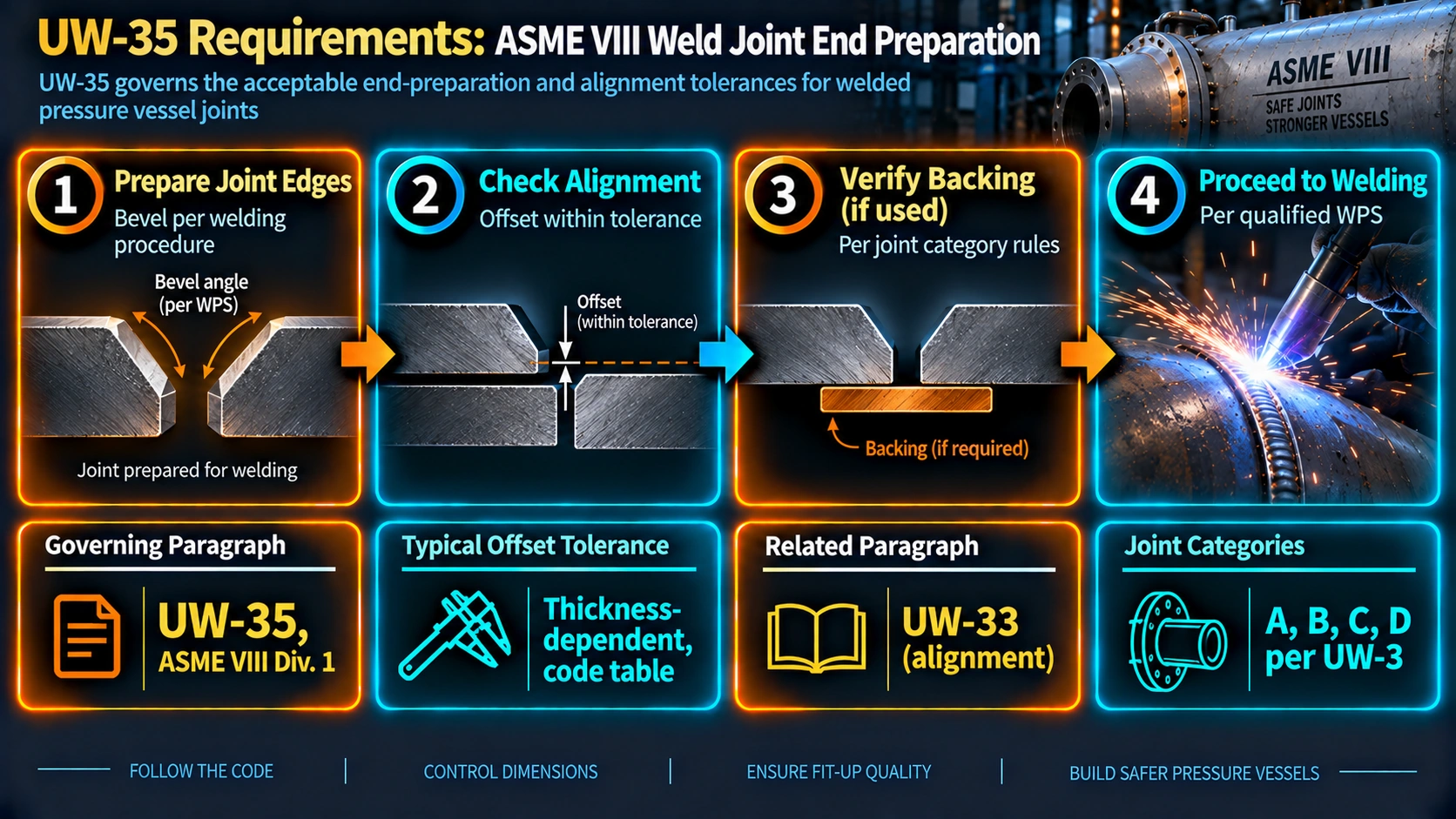
Paragraph UW-35 is structured into five distinct clauses, each addressing a different aspect of completed weld quality. They are lettered (a) through (e) and must all be satisfied concurrently — a weld that passes clause (e) on reinforcement but fails clause (c) on undercut is not acceptable under the code. The five clauses are:
| Clause | Subject | Key Requirement | Applies To |
|---|---|---|---|
| UW-35(a) | Complete Penetration & Full Fusion | All butt welds must achieve complete penetration and full fusion through the joint thickness | All butt-welded joints in pressure vessels |
| UW-35(b) | Weld Surface Condition | Surface must be free from coarse ripples, grooves, overlaps, abrupt ridges, and valleys that impair NDE interpretation | All welds subject to radiographic or other NDE |
| UW-35(c) | Undercut Limits | Undercut acceptable only within two simultaneous conditions: not below design thickness AND not exceeding 1/32 in (1 mm) or 10% of nominal thickness | All pressure-containing welds |
| UW-35(d) | Backing Strip Rule | For butt joints with permanent backing strip (Type No. 2, Table UW-12), reinforcement requirement applies only to the side opposite the backing | Single-welded butt joints with backing left in place |
| UW-35(e) | Weld Reinforcement Limits | Maximum reinforcement thickness by material nominal thickness and weld category — tabulated values in US Customary and SI units | All butt-welded joints; reinforcement on each face independently |
UW-35(a) — Complete Penetration and Full Fusion
The most fundamental requirement in UW-35 is also the most unambiguous: all butt-welded joints in pressure vessels shall have complete joint penetration and full fusion. This means the weld metal must extend through the full thickness of the joint and must achieve metallurgical fusion with both base metal sidewalls at every point along the joint length. There are no partial exceptions and no alternative acceptance criteria — incomplete penetration or lack of fusion in a butt weld is an unconditional rejection regardless of size, location, or claimed structural adequacy.
Why Complete Penetration Is Non-Negotiable
Lack of penetration (LOP) and lack of fusion (LOF) create planar defects — sharp-edged voids or unbonded interfaces — that behave as pre-existing cracks in the pressure boundary. Under cyclic pressure loading or thermal cycling, these defects propagate rapidly and can lead to sudden brittle fracture. Unlike volumetric defects such as porosity (which have rounded geometry), planar defects have very high stress concentration factors and are the leading cause of in-service weld failures in pressure equipment.
UW-35(b) — Weld Surface Condition
Clause (b) does not prohibit weld surface irregularities entirely — it requires that the surface be sufficiently smooth to permit proper interpretation of radiographic and other NDE examinations. Specifically, the weld surface shall be free from:
- Coarse ripples — heavy, irregular transverse undulations across the weld bead
- Grooves — longitudinal channels along the weld surface
- Overlaps — weld metal that has flowed over the base metal without fusion (a form of LOF at the surface)
- Abrupt ridges — sharp step changes in surface height between weld passes
- Valleys — depressions between weld beads that create concavity below the base metal surface
The purpose of this requirement is to ensure that NDE — specifically radiographic testing — can produce an interpretable image. A rough weld surface introduces false density variations on the radiographic film that can mask real defects (porosity, inclusions, cracks) underneath. The code includes an important provision: if there is a question regarding the surface condition when interpreting a radiographic image, the image shall be compared to the actual weld surface to determine acceptability. This means the radiographer must have access to the physical weld during film interpretation.
UW-35(c) — Reduction in Thickness Due to Undercut
Undercut — the groove melted into the base metal at the toe of a weld bead — is one of the most common weld surface defects in pressure vessel fabrication. Unlike porosity or inclusions which are internal, undercut is visible on the surface and measurable with a weld gauge. ASME UW-35(c) permits undercut only when both of the following conditions are simultaneously satisfied. If either condition is violated, the undercut must be repaired by depositing additional weld metal and dressing to an acceptable profile.
The reduction in thickness shall not reduce the material of the adjoining surfaces below the design thickness at any point. This means the remaining base metal at the undercut location must still be at least equal to the minimum required thickness calculated for the design pressure, temperature, and corrosion allowance.
The reduction in thickness shall not exceed the lesser of:
US Customary: 1/32 in (1 mm)
OR
10% of the nominal thickness of the adjoining surface
Whichever of these two values is smaller governs. For thin material, 10% of nominal thickness may be less than 1 mm and therefore controls.
UW-35(d) — Backing Strip (Type No. 2 of Table UW-12)
When a single-welded butt joint is produced using a backing strip that is left in place permanently (Type No. 2 of ASME Section VIII Table UW-12), the weld reinforcement requirement of UW-35(e) applies only to the side of the joint opposite the backing strip — that is, the accessible face. The backing strip side of the joint is exempt from the maximum reinforcement limit because the backing strip itself fills the root area and the joint geometry prevents meaningful reinforcement measurement on that face.
This rule has an important practical consequence: the inspector must correctly identify which side of the joint carries the backing strip before conducting the reinforcement measurement. Confusing the two faces could result in either missing an over-reinforced accessible face or incorrectly calling the backing-strip side for a reinforcement measurement that is not required by the code.
UW-35(e) — Weld Reinforcement Limits
Clause (e) is the most detail-rich part of UW-35 and is the one most directly used by welding inspectors as a go/no-go acceptance check. The requirement begins with an important positive statement: the butt-welded joints shall be completely filled so that the surface of the weld metal at any point does not fall below the surface of the adjoining base materials. Weld metal may be added as reinforcement on each face. However, the thickness of the reinforcement on each face shall not exceed the tabulated limits.
Two separate tables are given — one in US Customary (inch) units and one in SI (mm) units. Both are reproduced in full below.
Table UW-35(e) — US Customary Units (Inches)
| Material Nominal Thickness (in) | Maximum Reinforcement (in) | |
|---|---|---|
| Category B and C Butt Welds | Other Welds | |
| Less than 3/32 | 3/32 | 1/32 |
| 3/32 to 3/16, incl. | 1/8 | 1/16 |
| Over 3/16 to 1/2, incl. | 5/32 | 3/32 |
| Over 1/2 to 1, incl. | 3/16 | 3/32 |
| Over 1 to 2, incl. | 1/4 | 1/8 |
| Over 2 to 3, incl. | 1/4 | 5/32 |
| Over 3 to 4, incl. | 1/4 | 7/32 |
| Over 4 to 5, incl. | 1/4 | 1/4 |
| Over 5 | 5/16 | 5/16 |
Table UW-35(e) — SI Units (Millimetres)
| Material Nominal Thickness (mm) | Maximum Reinforcement (mm) | |
|---|---|---|
| Category B and C Butt Welds | Other Welds | |
| Less than 2.4 | 2.5 | 0.8 |
| 2.4 to 4.8, incl. | 3 | 1.5 |
| Over 4.8 to 13, incl. | 4 | 2.5 |
| Over 13 to 25, incl. | 5 | 2.5 |
| Over 25 to 51, incl. | 6 | 3 |
| Over 51 to 76, incl. | 6 | 4 |
| Over 76 to 102, incl. | 6 | 5.5 |
| Over 102 to 127, incl. | 6 | 6 |
| Over 127 | 8 | 8 |
Why the Limits Differ Between Categories
The table provides two different limits for the same material thickness: one for Category B and C butt welds and a lower limit for “other welds.” Category B and C are circumferential and attachment butt welds — they are typically accessible, can be ground if necessary, and their reinforcement is less likely to interfere with mating components. The higher allowance reflects the practical difficulty of controlling reinforcement on circumferential field or shop welds while still maintaining complete fill. “Other welds” (a category that includes nozzle-to-shell and attachment welds in certain geometries) have tighter limits because excess reinforcement on these welds creates more severe stress concentrations at the weld toe in a region of geometric discontinuity that is already a stress raiser.
Consequences of Excessive Weld Reinforcement
| Consequence | Engineering Explanation | Code/Practical Impact |
|---|---|---|
| Stress Concentration | The transition from weld crown to base metal at the weld toe creates a geometric notch. The sharper (higher reinforcement) this notch, the higher the local stress concentration factor (Kt). Under cyclic pressure loading, fatigue cracks initiate at the weld toe. | Reduced fatigue life; may require fitness-for-service assessment per API 579 if discovered in service |
| RT Interpretation Difficulty | Excess reinforcement increases the total thickness through which the X-ray beam must pass at the weld centreline relative to the base metal, creating high-contrast density gradients on the film that can obscure near-surface defects. | RT film may be uninterpretable at the weld centreline; grinding required before re-examination; wasted RT cost |
| Fit-Up Problems | Flanged nozzles, saddle supports, and mating gasket faces require a flush surface. Excess weld reinforcement on seam welds under saddle contact points causes point loading and bending stress. | Mechanical fit-up rejection; grinding required; dimension non-conformance on traveller |
| Weight & Material Waste | Excess weld metal represents wasted filler material, increased welding time, and unnecessary weight addition to the vessel — directly increasing fabrication cost. | Cost impact; welder skill/parameter control issue requiring WPS review |
Weld Joint Categories per UW-3 — Understanding the Reference in UW-35(e)
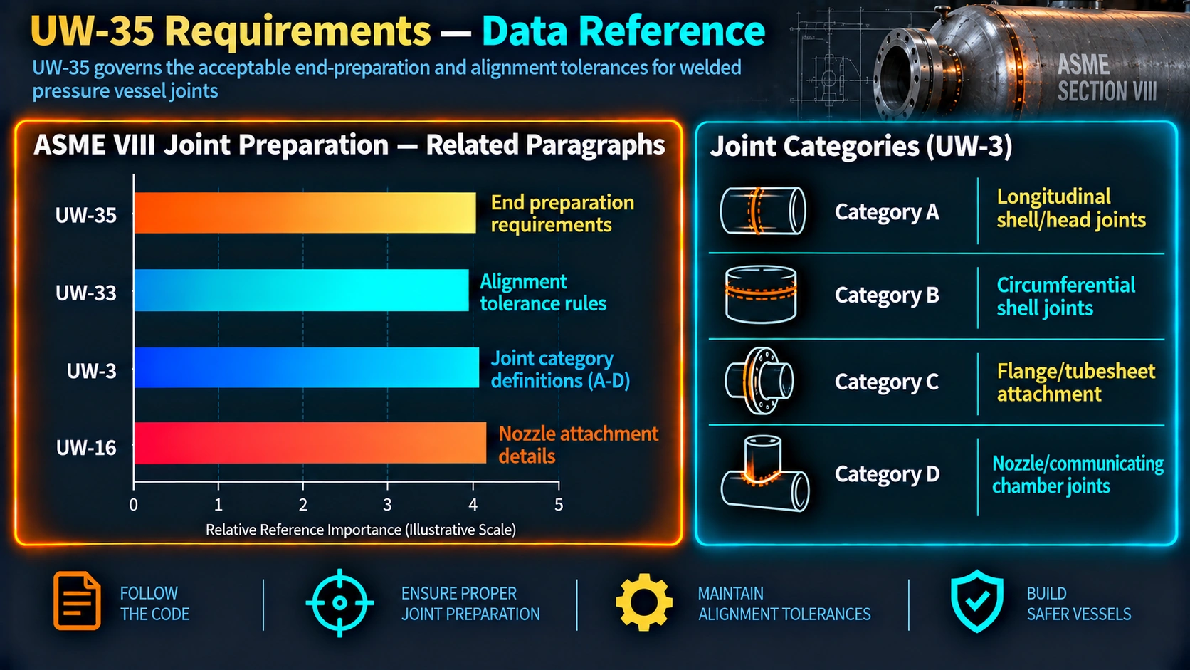
The UW-35(e) table references “Category B and C Butt Welds” and “Other Welds.” These categories are defined in paragraph UW-3 of ASME Section VIII Division 1. Understanding them is essential for correctly applying the reinforcement table. The four categories — A, B, C, and D — are defined by the orientation and location of the joint in the vessel, not by the type of weld preparation.
Category A
Longitudinal joints in shells, heads, and other major pressure parts. Also includes any weld in a sphere, formed head, or flat head.
Category B
Circumferential joints joining shells to shells, shells to transition sections, or shells to heads and other major parts.
Category C
Attachment joints for nozzles, flanges, tubesheets, flat heads, and access openings to the vessel shell or head.
Category D
Nozzle neck to shell or nozzle neck to head joints. Also covers branch connections into vessel shells.
UW-35 in the Context of the Weld Inspection Sequence
UW-35 acceptance criteria are applied during the visual examination of completed welds, which is the first NDE stage in the fabrication sequence. The visual inspection must be completed and accepted before any other NDE (RT, UT, MT, PT) is performed, because a weld with visible surface defects — excess reinforcement, undercut, overlaps — that fails UW-35 should be repaired before committing the cost of volumetric examination. The correct inspection sequence for a production weld is:
Recording UW-35 Results on the Weld Traveller
Every UW-35 visual inspection result must be formally recorded. The inspection record should include the weld number (from the weld map), the date of inspection, the inspector’s name and certification level, the measured values for undercut depth and reinforcement height, the applicable limits from UW-35(c) and (e), and the accept/reject result. Any repair, re-welding, and re-inspection must be documented with the same level of detail. These records form part of the final data book.
Key Points Summary — UW-35 Quick Reference
ASME UW-35 — Five-Clause Quick Reference
- UW-35(a): All butt welds must have complete joint penetration and full fusion — no exceptions, no alternative acceptance
- UW-35(b): Weld surface must be smooth enough for NDE interpretation — no coarse ripples, grooves, overlaps, abrupt ridges, or valleys
- UW-35(c): Undercut allowed only when: (1) remaining thickness ≥ design thickness AND (2) depth ≤ lesser of 1/32 in (1 mm) or 10% of nominal wall thickness
- UW-35(d): Backing strip (left in place) — reinforcement requirement applies to accessible face only; backing side is exempt
- UW-35(e): Reinforcement measured on each face independently; limits from tables vary by t and joint category (B&C butt welds vs. other welds)
- Excess reinforcement causes: stress concentration at weld toe, RT interpretation difficulty, fit-up problems, and material waste
- Visual inspection covers all five clauses before any NDE method is applied; all results recorded on traveller card and weld map
Common UW-35 Non-Conformances and Corrective Actions
| Clause | Common NCR Finding | Root Cause | Corrective Action |
|---|---|---|---|
| UW-35(a) | Incomplete root penetration identified on RT film | Root gap too small; travel speed too high; insufficient heat input on root pass | Back-gouge or grind root; re-weld root pass to WPS parameters; 100% RT re-examination of repaired area |
| UW-35(b) | RT film uninterpretable due to coarse weld surface | Weave bead technique with excessive oscillation; high travel speed | Dress weld surface with angle grinder (transverse grinding); verify wall thickness after grinding; repeat RT |
| UW-35(c) | Undercut depth 1.5 mm measured on 20 mm nominal wall | Excessive amperage on final pass; electrode angle too steep; travel speed too high | Undercut exceeds 1 mm limit — repair by depositing weld metal in undercut groove with low-hydrogen electrode; blend into base metal; re-inspect |
| UW-35(d) | Inspector measured reinforcement on backing strip face instead of cap face | Misidentification of weld faces; inadequate inspector training on UW-35(d) | Re-inspect correct face; update VT record; conduct inspector refresher training on UW-3 and UW-35(d) |
| UW-35(e) | Reinforcement 7 mm on 25 mm wall Category B seam (limit = 5 mm per SI table) | Excessive fill passes; lack of weld bead height monitoring; WPS interpass height not checked | Grind excess reinforcement to ≤5 mm; measure remaining wall; re-examine by VT + RT; update weld parameters in WPS pre-job review |
UW-35 and Related ASME Section VIII Requirements
UW-35 does not stand alone — it works alongside other ASME Section VIII Division 1 paragraphs that govern the quality of completed welds. Understanding the relationship between these paragraphs is essential for comprehensive weld quality control:
| Paragraph | Subject | Relationship to UW-35 |
|---|---|---|
| UW-3 | Joint Categories A, B, C, D | Defines the categories referenced in UW-35(e) reinforcement table |
| UW-12 | Joint Types and Efficiency Table | Defines Type No. 2 backing strip referenced in UW-35(d); governs which joint types require full penetration |
| UW-27 to UW-32 | Welding process requirements, PWHT, postweld operations | Define how the weld is made before UW-35 acceptance criteria apply |
| UW-51 | Radiographic examination of butt welds | Governs RT acceptance criteria; complements UW-35(b) surface requirements for film interpretation |
| UW-52 | Spot radiography | Sets RT acceptance limits for spot-examined welds — applied after UW-35 VT acceptance |
| ASME Section V, Art. 9 | Visual examination methods | Governs the VT technique used to apply UW-35 criteria; defines lighting, access, and documentation requirements |
| ASME Section IX | WPS / PQR / WPQ qualification | Ensures welds are made to qualified procedures; WPS parameters directly affect UW-35 compliance (heat input, technique, position) |
Recommended Books on ASME Section VIII and Weld Quality
Frequently Asked Questions — ASME UW-35
What does ASME UW-35 cover?
ASME Section VIII Division 1 paragraph UW-35 specifies five requirements for completed welds in pressure vessels: (a) complete penetration and full fusion for all butt welds; (b) acceptable weld surface condition free from ripples, grooves, overlaps, and abrupt ridges; (c) limits on undercut depth — not below design thickness AND not exceeding 1/32 in (1 mm) or 10% of nominal thickness, whichever is less; (d) the rule that for butt joints with a permanent backing strip, reinforcement applies only to the face opposite the backing; and (e) maximum weld reinforcement thickness tabulated by material nominal thickness and weld joint category in both US Customary and SI units. All five clauses must be satisfied simultaneously for a weld to be accepted.
What is the maximum weld reinforcement allowed under ASME UW-35?
Under ASME UW-35(e), maximum weld reinforcement is determined from tables based on material nominal thickness and weld category. For Category B and C butt welds in SI units: material under 2.4 mm allows 2.5 mm reinforcement; 2.4–4.8 mm allows 3 mm; over 4.8–13 mm allows 4 mm; over 13–25 mm allows 5 mm; over 25–51 mm allows 6 mm; over 51–102 mm allows 6 mm; over 102–127 mm allows 6 mm; over 127 mm allows 8 mm. Other welds have lower limits in the same table. Each face of the weld is measured independently — both faces must comply with their respective limits. See the full tables in the article above for all thickness ranges in both SI and US Customary units.
What are the two conditions for acceptable undercut under ASME UW-35?
ASME UW-35(c) permits undercut only when both conditions are satisfied simultaneously. Condition 1: the reduced thickness must not fall below the design thickness — the remaining metal at the undercut must be sufficient for the design pressure and temperature. Condition 2: the depth of undercut must not exceed the lesser of 1/32 in (1 mm) OR 10% of the nominal thickness of the adjoining surface. Both conditions apply at the same time — a weld that satisfies Condition 2 but violates Condition 1 (remaining wall below design minimum) must still be repaired. For thin materials, the 10% rule often governs and gives a limit well below 1 mm.
Why does excessive weld reinforcement cause problems?
Excessive weld reinforcement creates three primary problems. First, it introduces a stress concentration at the weld toe — the geometric notch between the weld cap and base metal — which reduces fatigue life under cyclic pressure loading. Second, it creates density variations on radiographic film, where the greater weld thickness at the crown makes the centreline appear denser than the base metal, potentially hiding internal defects. Third, it causes mechanical fit-up problems on nozzle faces, saddle contact zones, and mating flanged joints that require flush surfaces. ASME notes in UW-35 that excessive reinforcement can cause difficulties in radiographic interpretation, stress concentration, and fit-up issues and may require grinding and rework — adding cost and time to fabrication.
When does the backing strip reinforcement rule apply under UW-35(d)?
Per ASME UW-35(d), the special backing strip rule applies when a single-welded butt joint is made using a backing strip of Type No. 2 from Table UW-12 that is left in place permanently after welding. In this case, the weld reinforcement requirement of UW-35(e) applies only to the accessible face — the side opposite the backing. The backing strip face is exempt from the reinforcement thickness limit. This distinction is important for visual inspection — the inspector must correctly identify which face is the backing-strip side and measure reinforcement only on the accessible cap face. If the backing strip were subsequently removed, the root face would need to meet the normal reinforcement and surface requirements.
What are the four weld joint categories in ASME Section VIII Division 1?
ASME Section VIII Division 1 paragraph UW-3 defines four weld joint categories: Category A covers longitudinal joints in shells, heads, and other major parts, and all joints in spheres and formed heads. Category B covers circumferential joints joining shells to shells, shells to heads, or shells to transition sections. Category C covers joints attaching nozzles, flanges, access openings, and tubesheets to the vessel shell or heads. Category D covers nozzle neck-to-shell or neck-to-head joints. The category determines the required joint type from Table UW-12, the applicable radiographic examination extent, and — in UW-35(e) — the maximum permissible weld reinforcement thickness. See the ASME Section VIII quiz for practice questions on category classification.
What weld surface conditions are unacceptable under UW-35(b)?
ASME UW-35(b) prohibits weld surfaces that are not smooth enough to permit proper NDE interpretation. Specifically, the weld must be free from coarse ripples (irregular transverse undulations), grooves (longitudinal channels), overlaps (cold laps where weld metal flows over base metal without fusion), abrupt ridges (sharp step transitions between passes), and valleys (inter-bead concavities below the base metal surface level). If a radiographic image shows ambiguous density features that might be masked by surface condition, the code requires the image to be compared to the actual weld surface. Grinding to achieve an interpretable surface is permitted — but the remaining wall thickness must be verified after grinding to confirm compliance with minimum thickness requirements.
Can weld reinforcement be added on both faces of a butt weld?
Yes. ASME UW-35(e) explicitly states that weld metal may be added as reinforcement on each face of a butt weld to assure complete filling at the joint. Both faces may carry reinforcement, but each face is subject to its own independent limit from the UW-35(e) table based on the material nominal thickness and the weld category. Neither face’s excess can be offset against the other face being within limits. Grinding the reinforcement flush or below the table limit is always acceptable provided the minimum required thickness is maintained. Some owner and EPC specifications require reinforcement to be ground flush for all Category A seams (longitudinal joints) to eliminate the weld toe stress concentration in high-cycle service applications.