Weld Spatter — Causes and Prevention
Weld spatter is the scatter of small molten metal droplets thrown out of the arc and weld pool during welding, landing on the surrounding base metal, fixtures, and equipment. Every welder encounters it, but the amount varies enormously depending on process, parameters, equipment condition, and technique. A small amount is normal and unavoidable; heavy, persistent spatter is a signal that something in the welding setup is out of balance, and it comes with real costs in cleanup labor, consumable wear, and coating or paint adhesion problems downstream.
This guide breaks down exactly what causes spatter across MIG, stick, and flux-cored welding, and gives practical, parameter-level fixes that reduce it at the source rather than just cleaning it up after the fact. It covers arc transfer mode, voltage-to-wire-speed balance, polarity and arc blow, contamination, equipment wear, and the role of shielding gas, along with removal methods for spatter that does occur.
Scope note: This article focuses on spatter mechanisms and prevention in GMAW/MIG, SMAW/stick, and FCAW welding of carbon and low-alloy steel, which is where spatter is most commonly encountered in fabrication shops. TIG welding produces negligible spatter under normal conditions and is referenced only for comparison.
What Causes Weld Spatter
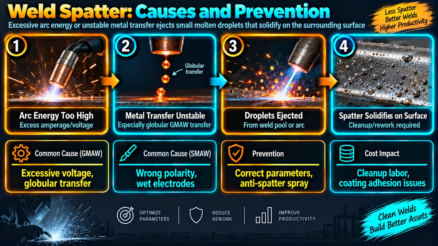
Spatter originates from instability in how the arc transfers molten metal from the electrode or wire into the weld pool. When that transfer is smooth and controlled, essentially all of the melted filler ends up in the weld bead. When it is violent or erratic, some of that molten metal is ejected outward instead of flowing into the pool.
Parameter Mismatch (Voltage vs. Wire Feed Speed / Amperage)
In short-circuit MIG transfer, the wire physically touches the weld pool many times per second. If wire feed speed or amperage is too high relative to voltage, the wire punches into the pool too aggressively and the resulting short circuit is more violent, expelling droplets outward as it clears. Conversely, voltage that is too high relative to wire speed can promote an unstable, overly long arc that also spatters. The correct combination is a narrow, process-specific window, not a single fixed setting.
Excessive Inductance or Arc Force Settings
Inverter-based MIG machines allow adjustment of inductance (sometimes labelled “arc control” or “pinch”), which governs how quickly current rises during the short circuit. Too little inductance causes an abrupt, explosive short-circuit clearing that throws spatter; too much inductance can make the arc feel sluggish and inconsistent. Most manufacturers set a reasonable default, but fine-tuning inductance is one of the most effective and underused spatter fixes on modern inverter power sources.
Contact Tip and Nozzle Condition
A worn, oversized, or spatter-clogged contact tip lets the wire wander off-centre, changing the electrical contact point inconsistently as the wire feeds through. This destabilises arc length and current delivery from one instant to the next, which shows up directly as increased spatter along with an inconsistent arc sound. Contact tips are inexpensive and should be replaced on a defined schedule rather than run until visibly damaged.
Arc Blow
Arc blow is the deflection of the welding arc caused by magnetic fields around the joint, most common in DC welding on ferromagnetic steel, near plate ends, close to the work clamp connection, or on parts carrying residual magnetism from prior operations like magnetic particle inspection. A deflected arc cannot maintain a stable, consistent pool and throws noticeably more spatter along with erratic bead shape.
Contamination and Moisture
Mill scale, rust, oil, paint, and moisture on the base metal or in the electrode coating all disrupt the arc and generate additional gas and vapor at the pool surface, which increases spatter. Damp stick electrode coatings are a particularly common and avoidable cause, since flux coatings absorb atmospheric moisture if stored or handled incorrectly.
Shielding Gas Composition
Gas composition directly affects transfer stability. Straight CO2 promotes a more globular metal transfer with inherently more spatter than an argon-CO2 blend, because CO2’s higher ionization energy and different arc characteristics make the droplet detachment less smooth. This is why nearly all production MIG welding on carbon steel uses an argon-rich blend rather than pure CO2, except where CO2’s deeper penetration is specifically needed.
Process-by-Process Spatter Comparison
| Process | Typical Spatter Level | Primary Driver | Best Reduction Strategy |
|---|---|---|---|
| TIG (GTAW) | Minimal | Rarely an issue | Maintain clean tungsten and correct gas flow |
| Pulsed MIG (GMAW-P) | Low | Pulse parameter tuning | Use synergic presets, verify wire/gas match |
| Spray transfer MIG | Low | Requires high voltage/amperage above transition point | Ensure parameters are above spray transition threshold |
| Short-circuit MIG | Moderate-High | Voltage/wire speed balance, inductance | Fine-tune voltage-to-wire-speed ratio, adjust inductance |
| FCAW (flux-cored) | Moderate | Wire type, polarity, gas coverage (gas-shielded FCAW) | Match polarity to wire type, verify gas flow |
| Stick (SMAW) | Moderate-High | Amperage, arc length, electrode condition | Correct amperage, keep arc length short, use dry electrodes |
Setting the Voltage-to-Wire-Speed Window
Caution: Chasing spatter by adjusting voltage and wire speed alone without checking inductance, contact tip condition, and gas flow first often leads to a setting that reduces spatter but sacrifices penetration or fusion. Rule out equipment and gas issues before making large parameter changes.
Polarity and Arc Blow Fixes
Where arc blow is suspected, first try relocating the work clamp to a more symmetric position relative to the joint, or split the ground connection across two points to balance the magnetic field. Welding toward the clamp rather than away from it, reducing amperage slightly, and switching to AC where the process allows are additional standard countermeasures. On parts that have been through magnetic particle inspection or handled near strong magnets, demagnetising before welding is often necessary.
Equipment and Consumable Maintenance
Shop tip: Keep a running replacement schedule for contact tips and nozzles rather than waiting for visible failure. A contact tip that has drifted even slightly oversized from wear will noticeably increase spatter well before it looks obviously worn.
Nozzle spatter buildup restricts gas flow and can cause turbulent, ineffective shielding, which further destabilises the arc. Regular dipping in anti-spatter compound, or periodic reaming, keeps the nozzle bore clear. Check the consumable nomenclature guide when selecting replacement tips, nozzles, and wire to ensure correct sizing for the wire diameter in use.
Removing Spatter That Does Occur
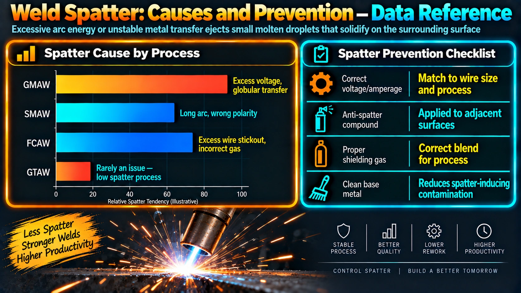
| Method | Best For | Notes |
|---|---|---|
| Anti-spatter spray/gel | Preventing adhesion before welding | Applied to base metal and nozzle beforehand; does not reduce spatter generation |
| Chipping hammer / scraper | Heavy, stuck-on spatter | Fast but can mark soft or coated surfaces |
| Grinding / flap disc | Cosmetic finish surfaces | Removes base metal too; use light passes on thin sheet |
| Wire brushing | Light, loosely adhered spatter | Least aggressive, good for stainless finish preservation |
Applications and Downstream Impact
Beyond the immediate cleanup labor, heavy spatter has real downstream costs. On parts headed for painting or powder coating, spatter globules create surface irregularities that show through the finish coat. On stainless fabrication, spatter can be a source of free iron contamination if not fully removed before passivation. On automated and robotic welding lines, spatter buildup on nozzles and fixtures is a leading cause of unplanned downtime, since it interferes with sensors, torch positioning, and gas coverage over time.
For related parameter reference, see WeldFabWorld’s MIG welding settings calculator and the GMAW/MIG process guide, both useful for cross-checking voltage and wire speed windows against the guidance in this article.
Amazon Picks for Spatter Control
Anti-Spatter Spray
Silicone-free anti-spatter spray for nozzles and base metal, reduces spatter adhesion and cleanup time.
View on AmazonMIG Welding Handbook
Covers transfer modes, parameter setting, and troubleshooting spatter and arc instability.
View on AmazonContact Tips and Nozzle Kit
Replacement MIG contact tips and nozzles across common sizes for scheduled consumable replacement.
View on AmazonChipping Hammer and Wire Brush Set
Standard slag and spatter removal tools for post-weld cleanup on steel and stainless.
View on AmazonDisclosure: WeldFabWorld participates in the Amazon Associates programme (StoreID: neha0fe8-21). If you purchase through these links, we may earn a small commission at no extra cost to you. This helps support free technical content on this site.
Frequently Asked Questions
What is the main cause of weld spatter in MIG welding?
In short-circuit MIG transfer, spatter is mostly caused by too much wire feed speed or amperage relative to voltage, which makes the wire short against the weld pool too violently and expel small droplets of molten metal when the arc re-establishes. Excessive inductance settings, too long a stick-out, and worn contact tips also increase spatter by destabilising the transfer. Correcting the voltage-to-wire-speed ratio is usually the single biggest fix.
Does arc blow cause spatter, and how do I fix it?
Yes. Arc blow is the deflection of the arc caused by magnetic fields, common in DC welding on ferromagnetic material, near the work clamp, at plate ends, or on parts with residual magnetism. A deflected arc struggles to maintain a stable pool and throws noticeably more spatter. Fixes include relocating or splitting the work clamp, welding away from plate ends where possible, using AC where practical, and demagnetising heavily magnetised parts before welding.
Can shielding gas choice reduce weld spatter?
Yes, gas composition has a significant effect. Straight CO2 produces more spatter than an argon-CO2 blend because CO2 promotes a more globular, less controlled metal transfer. Switching from 100 percent CO2 to a 90/10 or 95/5 argon-CO2 blend for MIG welding on carbon steel typically cuts spatter noticeably while keeping penetration acceptable, and is one of the easiest changes to make without retraining welders.
Why does spatter increase as a contact tip wears out?
A worn or oversized contact tip lets the wire wander off-centre inside the tip, which changes electrical contact point-to-point and destabilises the arc length and current delivery. This inconsistency shows up directly as increased spatter, along with erratic arc sound and inconsistent bead appearance. Contact tips are a low-cost, high-impact maintenance item and should be replaced on a set schedule rather than run until they visibly fail.
Does anti-spatter spray actually reduce spatter, or does it just help removal?
Anti-spatter spray does not reduce the amount of spatter generated by the arc itself; it works by preventing spatter that does land on the surrounding base metal and nozzle from sticking, so it can be wiped or brushed off instead of chipped or ground. It is a cleanup and nozzle-protection aid, not a substitute for correcting the underlying parameter or equipment issue that is generating excess spatter in the first place.
Is spatter more of a problem with stick welding or MIG welding?
Both processes can spatter heavily if parameters are wrong, but for different reasons. Stick welding spatters most from excessive amperage, a damp or contaminated electrode coating, and an arc length that is too long. MIG welding, particularly in short-circuit transfer, spatters most from an unbalanced voltage-to-wire-speed ratio. Pulsed MIG and spray transfer MIG, when the process allows it, generally produce the least spatter of the common arc welding processes. See our SMAW stick welding guide for more detail.
Does spatter affect weld quality, or is it only a cosmetic problem?
Heavy spatter is often a visible symptom of an unstable arc, and an unstable arc is also more likely to produce inconsistent penetration, porosity, and irregular bead profile. So while individual spatter globules on the surrounding plate are mostly a cosmetic and cleanup cost issue, persistent heavy spatter should be treated as a signal to check parameters, equipment condition, and technique rather than dismissed as purely cosmetic.