Welding Thin Sheet Metal — Tips to Avoid Burn-Through
Welding thin sheet metal is one of the most unforgiving jobs a welder can take on. Where a quarter-inch plate can absorb a slightly hot arc without much complaint, a sheet of 1 mm mild steel or 18 gauge stainless will blow a hole through the joint in a fraction of a second if the heat input, travel speed, or joint fit-up is even slightly wrong. Burn-through is not just cosmetic; it means re-fabricating the part, wasting filler and gas, and in production settings, missing schedule.
This guide breaks down exactly why thin gauge material burns through, and walks through the practical countermeasures that working welders and fabricators actually use: process selection between TIG, MIG, and pulsed MIG, amperage and travel speed windows for common thicknesses, joint design choices that add thermal mass exactly where you need it, and shop techniques like stitch welding and copper backing bars that turn a marginal setup into a controllable one.
Whether you are repairing automotive body panels, fabricating HVAC ductwork, or building thin-wall enclosures and cladding, the underlying physics is the same. Get the heat balance right and thin sheet welds cleanly, consistently, and with minimal distortion.
Scope note: This article covers carbon steel, stainless steel, and aluminum sheet in the roughly 0.6 mm to 3 mm (24 gauge to 11 gauge) range, using TIG, MIG, and pulsed MIG processes. Resistance spot welding and laser welding are referenced for comparison but are covered in depth in separate WeldFabWorld guides.
Why Thin Sheet Metal Burns Through
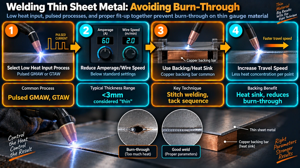
Burn-through happens when the rate of heat input from the arc exceeds the rate at which the surrounding base metal can conduct that heat away. On thick plate, there is a large volume of adjacent metal acting as a heat sink, so the weld pool stays contained. On thin sheet, that thermal mass simply is not there. The same arc energy that would produce a clean bead on 6 mm plate will punch straight through 1 mm sheet in an instant.
Three variables control this balance: amperage (how much energy the arc delivers per second), travel speed (how long the arc dwells over any one point), and thermal mass at the joint (how much surrounding metal is available to carry heat away). Get any one of these badly out of balance and the weld pool grows uncontrollably, sags, and eventually perforates the sheet.
Understanding this balance is the foundation for every technique in this article. Every fix below either reduces the rate of heat input, increases the rate of heat removal, or adds thermal mass at the joint so the arc has somewhere for its energy to go besides straight through the sheet.
Choosing the Right Process for Thin Gauge Work
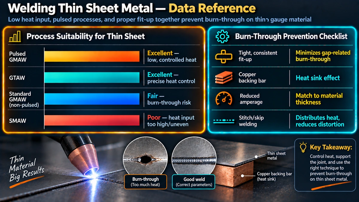
Not every welding process is equally suited to thin material. The table below compares the four processes most commonly used on sheet metal in the 0.6 mm to 3 mm range.
| Process | Heat Control | Typical Thickness Range | Skill Level | Best Use |
|---|---|---|---|---|
| TIG (GTAW) | Excellent | 0.5 mm – 3 mm | High | Precision fabrication, stainless, aluminum, visible welds |
| Pulsed MIG (GMAW-P) | Very good | 0.8 mm – 4 mm | Medium | Production runs needing speed with heat control |
| Short-circuit MIG | Fair | 1 mm – 6 mm | Low-Medium | General fabrication, less critical cosmetic finish |
| Stick (SMAW) | Poor | 2.5 mm and up | Medium | Not recommended below 2.5 mm |
For most repair and fabrication work under 2 mm, TIG welding remains the gold standard because the arc and the filler addition are two separate, independently controlled actions. A welder can hold a stable arc, dab in filler only as needed, and back off amperage instantly with a foot pedal the moment the pool starts to grow.
Pulsed MIG/GMAW is the production alternative. The pulsing cycles between a high peak current, which detaches the droplet, and a lower background current, which keeps the arc lit without dumping continuous heat into the sheet. This gives much of the heat control benefit of TIG at MIG travel speeds, which is why pulsed MIG has become the default choice in automotive body shops and thin-wall enclosure fabrication.
Conventional short-circuit MIG can still be used on thin sheet, but the operator has less margin for error since wire feed speed and voltage are locked together and there is no independent amperage control mid-weld. Stick welding (SMAW) is generally not recommended below about 2.5 mm; the minimum stable arc length and amperage needed to keep an electrode running is usually already too hot for thinner material.
Amperage and Travel Speed Starting Points
The table below gives practical starting points for mild steel. These are starting points only — always run a test coupon of the same thickness, joint type, and fit-up before welding the actual part, since machine calibration, polarity, and fit-up tolerance all shift the ideal setting.
| Thickness | TIG Amperage (DCEN) | Tungsten Dia. | MIG Wire Dia. | Pulsed MIG Avg. Current |
|---|---|---|---|---|
| 0.6 mm (24 ga) | 15-25 A | 1.0 mm | 0.6 mm | 25-40 A |
| 1.0 mm (20 ga) | 30-45 A | 1.6 mm | 0.6-0.8 mm | 40-60 A |
| 1.5 mm (16 ga) | 45-65 A | 1.6 mm | 0.8 mm | 60-85 A |
| 2.0 mm (14 ga) | 65-90 A | 2.4 mm | 0.8-0.9 mm | 85-110 A |
| 3.0 mm (11 ga) | 90-130 A | 2.4 mm | 0.9-1.0 mm | 110-150 A |
Caution: Heat input formulas are a planning guide, not a substitute for a test coupon. Arc voltage in particular is hard to measure precisely on shop equipment, so treat the calculated figure as an order-of-magnitude check rather than an exact pass/fail number.
Joint Design: Add Thermal Mass Where the Arc Needs It
Joint geometry has as much influence on burn-through as amperage does. The goal is to put extra metal exactly where the arc will be concentrated, without adding so much bulk that it defeats the purpose of using thin sheet in the first place.
Lap Joints
A lap joint is the most forgiving option for thin sheet because the overlapping material effectively doubles the local thickness at the joint. The arc has roughly twice the thermal mass to work with compared to a butt joint of the same nominal sheet thickness, which is why lap joints are the default choice in ductwork and light enclosure fabrication.
Flanged and Hemmed Edge Joints
A flanged joint, where the sheet edge is bent up before welding, achieves a similar effect to a lap joint while keeping a flush external appearance. This is standard practice in automotive panel work, where a visible, grindable weld line is required but a lap joint’s stepped profile is not acceptable.
Butt Joints
A square-edge butt joint is the least forgiving geometry on thin sheet and should be fitted with essentially zero root gap. Any gap forces the welder to add filler and heat to bridge it, and that extra heat is exactly what causes burn-through. On material under 1.5 mm, even a 0.3 mm gap can be the difference between a clean weld and a blown-through one.
See WeldFabWorld’s full reference on welding joint types for geometry and code-based joint classification across all thickness ranges.
Heat Sinks and Backing Bars
A copper backing bar or copper heat sink clamp placed directly behind the joint is one of the most effective tools for thin sheet welding. Copper has roughly ten times the thermal conductivity of mild steel, so it pulls heat away from the weld pool far faster than the surrounding sheet ever could. Copper also does not fuse to steel or aluminum at normal arc temperatures, so the same backing bar can be reused indefinitely.
Shop tip: A section of copper bar with a shallow groove machined along the joint centreline also helps control root reinforcement on butt joints, giving a slightly convex, consistent root bead instead of an uncontrolled sag-through.
Where copper is not practical, a simple steel heat sink clamp, a wet rag wrapped near the joint (well clear of the weld pool), or even aluminum finger clamps along the joint edge can meaningfully slow heat buildup on longer runs. On aluminum sheet specifically, a chill bar is almost mandatory given aluminum’s very high thermal conductivity combined with its low melting point relative to steel.
Stitch Welding and Skip Sequencing
Stitch welding, also called skip welding, is the simplest technique available to any welder regardless of process or equipment. Instead of running one continuous bead down the full joint length, the welder lays short segments, typically 15-25 mm long, at scattered points along the joint, allowing each segment to cool to the touch before returning to weld an adjacent segment.
This breaks the cumulative heat buildup that causes burn-through and warping on long continuous runs. It is standard practice in automotive body panel repair, where a continuous bead down a door skin or fender would almost certainly warp the panel and risk blowing through even with correct amperage.
Sequencing note: A common skip pattern is to divide the joint into thirds, weld the first third, skip to the far end and weld backward into the second third, then fill the remaining gaps. This spreads heat input across the whole joint rather than letting it accumulate at one end.
Filler Metal and Electrode Selection
Filler wire and electrode diameter should scale down with sheet thickness just as amperage does. An oversized filler rod or wire dumps a large, cold mass into a small weld pool, which the welder then has to add extra heat to fuse in, defeating the purpose of a controlled low-amperage setting. As a rule, filler diameter should be roughly equal to or slightly less than the sheet thickness itself for TIG work on material under 2 mm.
On stainless steel and aluminum sheet, filler alloy selection also affects weldability and burn-through resistance. Refer to WeldFabWorld’s consumable nomenclature guide for how to read filler and electrode classification codes when selecting the correct alloy match.
Shielding Gas Selection
Shielding gas composition has a real, if secondary, effect on arc heat and burn-through risk. Gas blends weighted toward CO2 or helium produce a hotter, more penetrating arc with more spatter, while argon-rich blends produce a cooler, more focused, more controllable arc.
| Material | Process | Recommended Gas | Notes |
|---|---|---|---|
| Mild steel | MIG | 90% Ar / 10% CO2 | Cooler, more controllable than straight CO2 |
| Mild steel | TIG | 100% Argon | Standard for thin gauge TIG |
| Stainless steel | MIG/TIG | 98% Ar / 2% CO2 or 100% Ar | Minimises heat and surface oxidation |
| Aluminum | TIG | 100% Argon | AC balance also affects heat and cleaning action |
Common Defects Beyond Burn-Through
Excess heat on thin sheet rarely causes burn-through in isolation; it usually shows up alongside these related defects as well.
| Defect | Cause | Fix |
|---|---|---|
| Warping / distortion | Uneven or excessive heat input across the panel | Stitch welding, symmetric weld sequence, clamping/fixturing |
| Excessive undercut | Travel speed too fast relative to amperage | Slow travel slightly or reduce amperage to match |
| Blow holes / porosity | Contamination, gas coverage loss at high travel speed | Clean joint thoroughly, check gas flow and nozzle stand-off |
| Discoloration (stainless) | Excess heat input and poor gas coverage | Reduce heat input, add trailing/backing gas shield |
Applications and Industry Context
Thin sheet welding shows up across a wide range of fabrication work: automotive body panel repair and restoration, HVAC ductwork, stainless kitchen and food-processing equipment, thin-wall enclosures and cabinets, and light structural cladding. In each of these, the same core principles apply: match the process to the thickness, control amperage and travel speed as a pair, and use joint design and heat sinks to buy margin rather than relying on operator skill alone to compensate for a marginal setup.
For related calculator tools and welding parameter references, see WeldFabWorld’s MIG welding settings calculator and TIG welding settings calculator, both of which can be used to sanity-check the starting points given in this article against your specific machine and joint.
Amazon Picks for Thin Sheet Welding
TIG Welding Handbook
Covers arc control, pedal technique, and settings for thin gauge stainless, aluminum, and mild steel.
View on AmazonSheet Metal Fabrication Guide
Practical reference on joint design, flanging, hemming, and forming for thin gauge fabrication work.
View on AmazonCopper Backing Bar Set
Machined copper heat sink bars for thin sheet butt joints, reusable across mild steel and aluminum work.
View on AmazonAuto Body Panel Welding Guide
Focused on stitch welding technique, panel replacement, and distortion control for automotive sheet metal.
View on AmazonDisclosure: WeldFabWorld participates in the Amazon Associates programme (StoreID: neha0fe8-21). If you purchase through these links, we may earn a small commission at no extra cost to you. This helps support free technical content on this site.
Frequently Asked Questions
What is the best welding process for thin sheet metal?
For most shop and fabrication work, TIG (GTAW) gives the best control over heat input on material under 2 mm thick because the arc and filler addition are separate actions. Pulsed MIG (GMAW-P) is faster for production runs and also controls heat well once the pulse parameters are dialed in. Conventional short-circuit MIG and stick welding are harder to control on very thin gauges and are more prone to burn-through unless amperage and travel speed are carefully matched.
Why does thin sheet metal burn through so easily?
Thin sheet has very little thermal mass, so it cannot absorb and dissipate arc heat the way thicker plate can. Once the heat input rate from the arc exceeds the rate at which the surrounding metal can conduct heat away, the weld pool grows faster than it should, the base metal melts through, and a hole or excessive sag results. Poor fit-up, high amperage, slow travel speed, and continuous non-stitched welding all make this worse.
What amperage should I use for 1 mm or 18 gauge sheet metal?
As a starting point for TIG on 1 mm mild steel, use roughly 30 to 45 amps DCEN with a 1.6 mm tungsten and 1.6 mm filler, adjusted by pedal or foot control. For MIG on the same thickness, short bursts of 40 to 60 amps with 0.6 to 0.8 mm wire and a fast travel speed usually work, but pulsed MIG at a low background current is more forgiving. Always run a test coupon of the same thickness and joint type before committing to the actual part.
Does a copper backing bar really help prevent burn-through?
Yes. A copper backing bar acts as a heat sink directly behind the joint, pulling heat away from the weld pool far faster than the surrounding thin sheet can on its own. This lets you run a slightly higher, more stable amperage without blowing through, and it also helps control root profile on butt joints. Copper does not fuse to steel or aluminum at normal welding temperatures, so it can be reused many times.
Should I use stitch welding or a continuous weld on thin sheet?
Stitch welding, also called skip welding, is one of the simplest and most effective ways to manage heat input on thin material. By welding short segments and allowing each one to cool before moving to the next, you avoid the cumulative heat buildup that causes burn-through and warping on long continuous runs. This technique is standard practice in automotive sheet metal repair and general thin-gauge fabrication.
What joint design is best to avoid blowing through thin sheet?
A tight-fitting butt joint with zero to minimal root gap is best for thin sheet, since any gap forces you to add more heat to bridge it, which increases burn-through risk. A flanged or hemmed edge joint is even more forgiving because the doubled-up material at the joint adds thermal mass exactly where the arc is concentrated. Lap joints are the easiest of all to weld on thin sheet since the overlapping metal itself acts like a built-in heat sink. See our guide on welding joint types for more detail.
Does shielding gas choice affect burn-through risk?
Shielding gas has an indirect but real effect. A gas blend with higher argon content and lower CO2 or helium produces a cooler, more focused arc with less spatter and heat spread compared to gas mixes weighted toward CO2 or helium, which run hotter. For thin steel, a 90 percent argon and 10 percent CO2 blend, or 100 percent argon for TIG, gives a more controllable, lower heat arc than straight CO2 or high-helium blends.