Tool Steel Welding and Repair Guide
Tool steel welding is one of the least forgiving jobs in the welding trade. A die insert, punch, or mold cavity that took hundreds of hours to machine can be scrapped in seconds by a single heat affected zone crack, and that crack often does not show up until the tool is back in the press and under load. Understanding tool steel welding and repair is therefore less about arc technique and more about metallurgical control: preheat, interpass temperature, filler selection, and post weld tempering all have to line up correctly, every time.
This guide walks through the full repair welding workflow for common tool steel families, including the O, A, D, H, S, and M groups defined under AISI classification. You will find preheat and interpass tables by group, filler metal selection logic, a step-by-step die repair sequence, post weld heat treatment requirements, and the cracking mechanisms that cause most tool steel repair failures. Whether you are welding up a worn punch corner, rebuilding a forging die edge, or repairing a plastic injection mold cavity, the same underlying principles apply.
Tool steel repair welding sits at the intersection of two disciplines that do not always talk to each other: the toolmaker who knows the part’s dimensional and hardness requirements, and the welder who controls heat input and cooling rate. Getting both sides right is what separates a repair that lasts the life of the tool from one that fails on the first production cycle.
Why Tool Steel Is Difficult to Weld
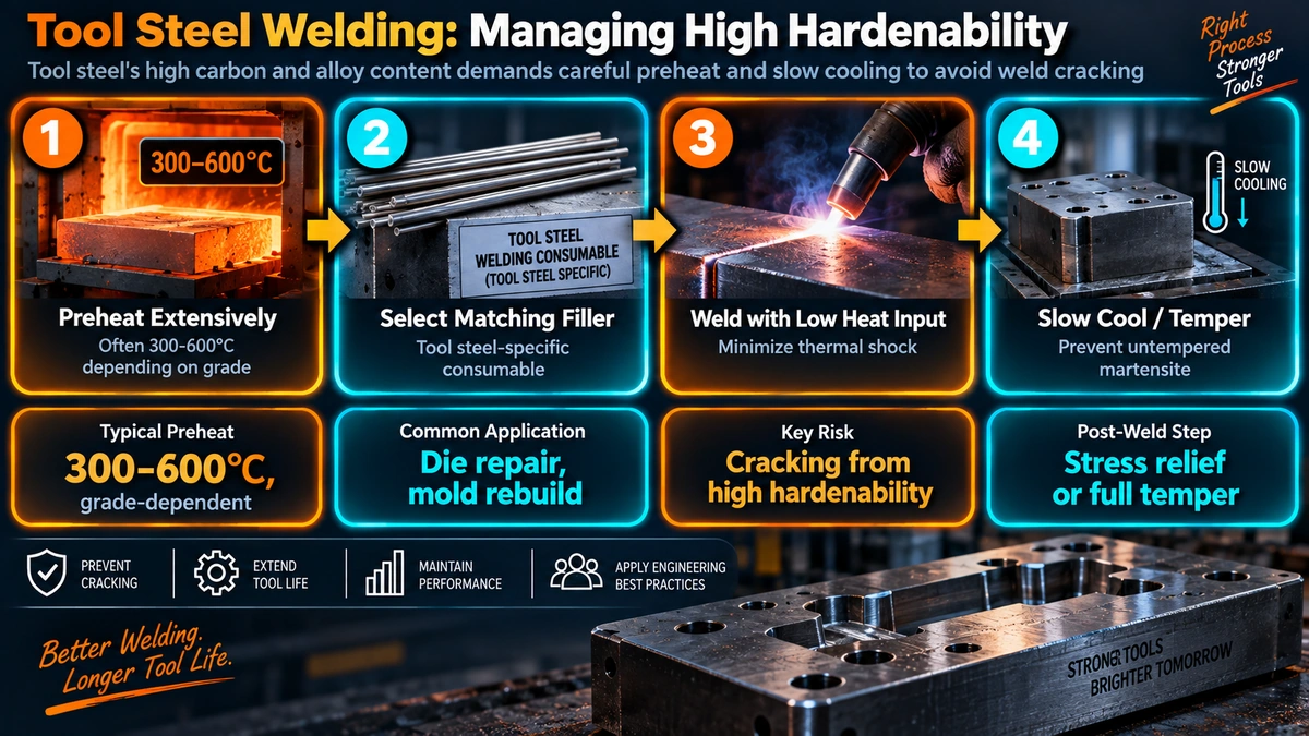
Tool steels are defined by high carbon content, typically between 0.5 and 2.3 percent, combined with substantial alloying additions of chromium, molybdenum, vanadium, tungsten, or cobalt depending on the grade. These elements are exactly what give tool steel its hardness, wear resistance, and hot strength in service, and they are exactly what makes it prone to cracking during and after welding.
When the arc passes over the base metal, the heat affected zone is briefly heated above the austenitizing temperature and then cools rapidly, often faster than the tool steel’s own critical cooling rate. Because tool steels are formulated for high hardenability specifically so that they harden through in the vacuum furnace or salt bath, that same hardenability means the heat affected zone forms hard, brittle, untempered martensite during welding. Untempered martensite has essentially no ductility and is the direct cause of heat affected zone cracking, whether the crack appears the moment the weld cools or hours to days later as a delayed crack.
The practical implication is that tool steel welding is a heat treatment problem wrapped around a joining problem. Every repair procedure has three phases that matter equally: preheat and interpass control before and during welding, deposit and heat affected zone chemistry during welding, and prompt post weld tempering after welding. Skipping any one of the three is the most common cause of repair failure reported by die shops and mold repair facilities.
Tool Steel Classification and Common Grades
AISI groups tool steels by their primary characteristic and intended hardening method. Selecting the correct preheat and filler for a repair starts with correctly identifying which group the tool belongs to, since carbon content and alloy content vary widely between groups.
| AISI Group | Typical Grades | Carbon Content | Primary Use | Weldability |
|---|---|---|---|---|
| Water hardening | W1, W2 | 0.6-1.4% | Cutting tools, blanking dies | Difficult |
| Oil hardening | O1, O2, O6 | 0.9-1.5% | Gauges, precision blanking dies | Fair with care |
| Air hardening | A2, A6 | 1.0% | Punches, forming dies | Fair with care |
| High carbon-chromium | D2, D3 | 1.5% | Blanking and cold forming dies | Difficult |
| Chromium hot-work | H11, H13 | 0.35-0.4% | Die casting dies, forging dies, extrusion tooling | Good |
| Shock resisting | S5, S7 | 0.5% | Chisels, punches, pneumatic tools | Good |
| Molybdenum high speed | M2, M4 | 0.8-1.3% | Cutting tools, drills, taps | Difficult |
| Plastic mold steel | P20, NAK80 | 0.3-0.4% | Injection mold cavities and cores | Good |
The hot-work chromium grades such as H13 are the most weld-friendly tool steels because their moderate carbon content (around 0.4 percent) gives a much lower as-quenched hardness and a wider tempering window than the high carbon D or M group steels. This is one reason H13 has become the default choice for die casting and forging tooling that regularly needs field repair.
Reading a Tool Steel Specification Correctly
Before welding, confirm the exact grade, current hardness, and heat treatment condition of the tool, not just the nominal AISI designation. A punch stamped D2 that has already been through hardened to 58-60 HRC behaves very differently under the torch than annealed D2 bar stock. Understanding the tool’s carbon equivalent gives a useful first estimate of relative hardenability and cracking susceptibility, in the same way it does for structural and pressure part steels, even though tool steel formulas are not typically expressed this way in industry literature.
Preheat and Interpass Temperature Requirements
Preheat is the single most important control variable in tool steel welding. Its purpose is to slow the cooling rate through the martensite start temperature so that the heat affected zone forms a more tempered, less brittle microstructure, and to reduce the thermal gradient between the weld deposit and the surrounding cold mass of the die or mold block.
| Tool Steel Grade | Preheat Temp | Interpass Max | Notes |
|---|---|---|---|
| H13, H11 | 550-650 F (290-345 C) | 650 F (345 C) | Match preheat to original tempering temperature where known |
| P20, NAK80 | 300-400 F (150-205 C) | 500 F (260 C) | Lower carbon allows lower preheat |
| A2, A6 | 500-600 F (260-315 C) | 600 F (315 C) | Air hardening; slow, controlled cooling is critical after welding |
| O1, O2 | 400-500 F (205-260 C) | 550 F (290 C) | Oil hardening steels can distort if cooled unevenly |
| D2, D3 | 600-700 F (315-370 C) | 700 F (370 C) | Highest risk group; slow post-weld cooling in an insulated blanket or furnace |
| S7, S5 | 400-500 F (205-260 C) | 550 F (290 C) | Shock resisting grades tolerate moderate preheat well |
| M2, M4 | 600-700 F (315-370 C) | 700 F (370 C) | High speed steels are extremely crack sensitive; specialist repair only |
How Preheat Interacts With Section Size
Large die blocks act as a heat sink. A local torch preheat on a massive block loses heat into the surrounding mass faster than it can be replenished, so interpass temperature drifts down during long repair sequences unless preheat is continuously maintained. For dies over roughly 150 mm thick, oven preheat of the entire block, or induction preheat concentrated around the repair zone, gives far more consistent results than spot torch heating.
Welding Process Selection
Process choice for tool steel repair depends on the size of the defect, the required deposit hardness, and how much heat input the surrounding tool can tolerate without distortion.
| Process | Best For | Heat Input | Typical Use Case |
|---|---|---|---|
| GTAW (TIG) | Precision repairs, thin sections, cavity detail | Low, well controlled | Mold cavity repair, punch corner buildup, cosmetic surface defects |
| Micro-TIG / pulsed arc welding | Very fine repairs on hardened, finished surfaces | Very low | Injection mold parting lines, polished cavity surfaces |
| SMAW (Stick) | Larger buildups, field repair away from shop | Moderate to high | Forging die edge buildup, large punch faces |
| Laser welding | Minimal heat affected zone repairs | Very low, highly localized | Fine cavity detail repair on finished, hardened tooling |
| PTA / plasma transferred arc | Wear surface rebuilding | Moderate | Large forming die faces requiring hardfacing overlay |
For most job-shop die and mold repair, GTAW is the default choice because it allows the welder to control puddle size and heat input precisely enough to avoid disturbing adjacent hardened surfaces. SMAW remains useful for larger forging and stamping die rebuilds where deposition rate outweighs the need for fine control, provided low-hydrogen electrodes are used and baked according to manufacturer recommendations.
Filler Metal Selection
Selecting the filler metal is a trade-off between matching properties and minimizing cracking risk. Three general strategies are used in practice.
| Strategy | Filler Approach | When to Use | Trade-off |
|---|---|---|---|
| Matching filler | Filler chemistry matches parent tool steel grade (e.g., D2-matching rod on a D2 die) | Full hardness and wear resistance required across the repair | Highest cracking risk; requires full re-harden and re-temper cycle after welding |
| Buffer/underlay filler | Softer, tougher nickel-chromium or low-alloy rod deposited first, then matching filler on top if needed | Most general die and mold repairs | Lower hardness in the buffer layer, but dramatically reduced cracking |
| Full buffer only | Entire repair made with tough, crack-resistant filler, no matching top layer | Cosmetic or low-wear areas, non-critical repairs | Repair area will not match parent hardness; not suitable for high-wear zones |
Step-by-Step Die Repair Procedure
The following sequence reflects standard practice for repairing a worn or chipped area on a hardened tool steel die insert.
Post Weld Heat Treatment and Tempering
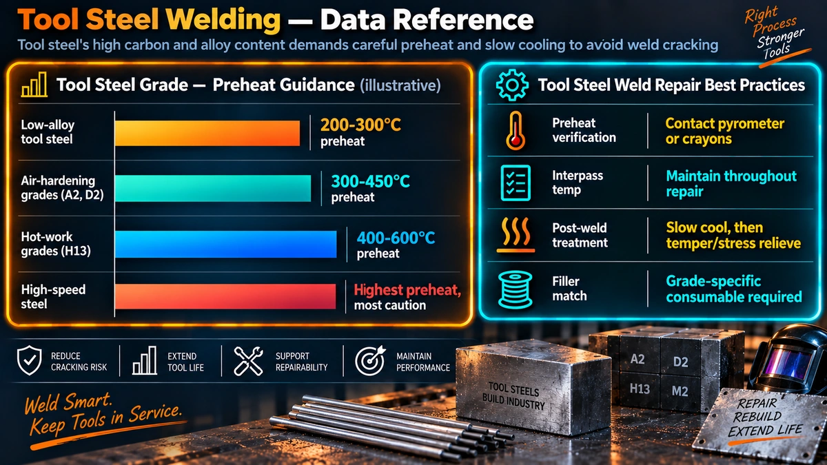
Post weld tempering is not optional on any hardenable tool steel repair. Its purpose is to convert the untempered, brittle martensite formed in the heat affected zone and weld deposit into a tempered, tougher microstructure before the part is returned to service or subjected to further machining stress.
| Grade | Typical Original Temper | Post-Weld Temper Target | Cycles |
|---|---|---|---|
| H13 | 1000-1100 F (540-595 C) | Match or 25 F below original | 2 cycles, 2 hrs each |
| D2 | 400-1000 F (205-540 C) depending on target hardness | At or below original temper | 2-3 cycles, 1-2 hrs each |
| A2 | 350-1000 F (175-540 C) | At or below original temper | 2 cycles, 2 hrs each |
| O1 | 350-500 F (175-260 C) | At or below original temper | 1-2 cycles, 1-2 hrs each |
| P20 | Pre-hardened, 300-400 HB typical | Stress relieve at 400-450 F (205-230 C) | 1 cycle, 2 hrs |
Common Defects and Cracking Mechanisms
Heat Affected Zone Cracking
This is the most frequent failure mode and typically appears as a crack running parallel to the fusion line, just outside the weld deposit itself. It results from untempered martensite combined with the residual stress of rapid cooling and shrinkage.
Delayed (Hydrogen-Assisted) Cracking
Delayed cracking can appear hours or even days after welding, once hydrogen picked up from moisture in electrode coatings, shielding gas, or surface contamination has had time to diffuse into susceptible microstructure. Using low-hydrogen consumables, properly baked electrodes, and clean, dry base metal reduces this risk substantially.
Solidification Cracking
Occurring within the weld deposit itself rather than the heat affected zone, solidification cracking is associated with high dilution from the base metal, sulfur or phosphorus segregation, and overly convex or narrow weld bead profiles that concentrate shrinkage stress along the centerline.
Reheat Cracking
Multi-pass repairs on highly alloyed tool steel can experience reheat cracking in the heat affected zone of earlier passes when reheated by subsequent passes, particularly if interpass temperature is allowed to swing too widely.
Distortion Control and Dimensional Considerations
Because tool steel repairs are often made on finished or near-finished dimension tooling, minimizing distortion matters as much as avoiding cracking. Balanced weld sequencing, symmetric buildup where possible, and controlled interpass temperature all help keep the repaired area within final machining allowance. Where the tool geometry allows it, welding in a fixture that restrains the part in its as-machined orientation reduces the chance that shrinkage pulls a critical dimension out of tolerance.
Documentation and Repeatability
Because tool steel repair is high risk and often performed under production time pressure, having a written procedure for each grade in the shop’s tooling inventory pays for itself quickly. A simple repair travel sheet recording preheat temperature achieved, filler used, interpass readings, and post weld temper cycle creates a record that can be referenced the next time the same die needs repair, and helps identify tools that are chronic repeat offenders for cracking.
Recommended Reference Reading
Tool Steels Handbook
Comprehensive metallurgical reference covering tool steel classification, heat treatment, and failure analysis for die and mold applications.
View on AmazonWelding Metallurgy Reference
Covers heat affected zone transformation, hardenability, and cracking mechanisms relevant to high carbon and alloy steel welding.
View on AmazonContact Pyrometer / IR Thermometer
Essential for verifying preheat and interpass temperature directly at the weld location during tool steel repair.
View on AmazonPortable Hardness Tester
Useful for verifying post-weld temper hardness on repaired die and mold surfaces without sectioning the tool.
View on AmazonDisclosure: WeldFabWorld participates in the Amazon Associates programme (StoreID: neha0fe8-21). If you purchase through these links, we may earn a small commission at no extra cost to you. This helps support free technical content on this site.
Frequently Asked Questions
What is the biggest risk when welding tool steel?
Cracking is the dominant risk. Tool steels carry 0.5 to 2.3 percent carbon plus heavy alloying, so the heat affected zone forms untempered, brittle martensite unless preheat, slow cooling, and prompt tempering are controlled tightly.
Can D2 tool steel be welded without preheat?
No. D2 has roughly 1.5 percent carbon and 12 percent chromium, giving it very high hardenability. Welding without preheat almost always produces heat affected zone cracking, either immediately or within hours of cooling.
Should I match the filler metal to the base tool steel grade?
Only when the repaired area must retain the full hardness and wear resistance of the parent grade, and full re-hardening and tempering afterward is feasible. For most die and mold repairs, a slightly softer, tougher buffer filler reduces cracking risk while still providing good service life. See our notes on consumable nomenclature for how filler alloy systems are classified.
Is TIG or SMAW better for tool steel repair?
GTAW is generally preferred for tool steel because it gives precise heat input control, a small and shallow heat affected zone, and clean deposits without slag inclusions. SMAW is used for larger buildups where deposition rate matters more than precision. Review our GTAW guide and SMAW guide for process fundamentals.
How soon after welding must tool steel be tempered?
As soon as the part reaches roughly 150 to 200 F (65 to 95 C), it should go into the tempering furnace, ideally within one to two hours. Letting a freshly welded high carbon tool steel sit at room temperature for an extended period significantly raises delayed cracking risk.
What preheat temperature should I use for H13 die repair?
H13 is typically preheated to 550 to 650 F (290 to 345 C) and held at that interpass temperature throughout welding, because H13 dies are usually already through hardened and tempered before repair welding begins.
Why does a tool steel weld repair sometimes crack days later?
Delayed or hydrogen assisted cracking occurs when untempered martensite in the heat affected zone is loaded by residual stress while retained hydrogen diffuses through the lattice. Slow cooling, adequate preheat, low hydrogen consumables, and prompt post weld tempering all reduce this risk.
Can I weld a cracked tool steel die back into service?
Yes, in most cases, provided the crack is fully removed by grinding to sound metal, the repair follows a qualified preheat and PWHT cycle, and the repaired zone is inspected by magnetic particle or dye penetrant testing before the die returns to production.