Welding Dissimilar Metals: A Complete Guide
Welding dissimilar metals – joining two base metals of different chemistry, such as carbon steel to stainless steel, or stainless to a nickel superalloy – is one of the most common sources of avoidable weld failure in industry. The joint often looks perfectly normal after welding and only fails weeks or months later from brittle cracking or accelerated corrosion, because the real problem was never visible on the surface: it was decided by the resulting weld metal chemistry the moment dilution mixed the two base metals with the filler.
This guide walks through the tools engineers actually use to plan these joints – the Schaeffler and WRC-1992 diagrams, dilution estimation, and galvanic compatibility – along with practical filler selection tables for the combinations you will meet most often: carbon steel to stainless steel, stainless to duplex, and steel to nickel alloy. We will also cover the buttering technique used when the two sides of a joint need different heat treatments.
If you already work with duplex stainless steel or creep-strength enhanced ferritic steels like P91, you have likely run into dissimilar joints already without necessarily framing the filler choice in these terms. This guide gives you the underlying logic so you can apply it to any combination, not just the ones covered by a standard’s lookup table.
Scope note: This guide focuses on fusion-welded dissimilar joints between common structural and process alloys – carbon steel, austenitic stainless steel, duplex stainless steel, and nickel-based superalloys. Explosion-bonded and friction-welded transition joints (e.g., aluminum to steel) follow different rules and are outside this scope.
Why Dissimilar Joints Fail Differently
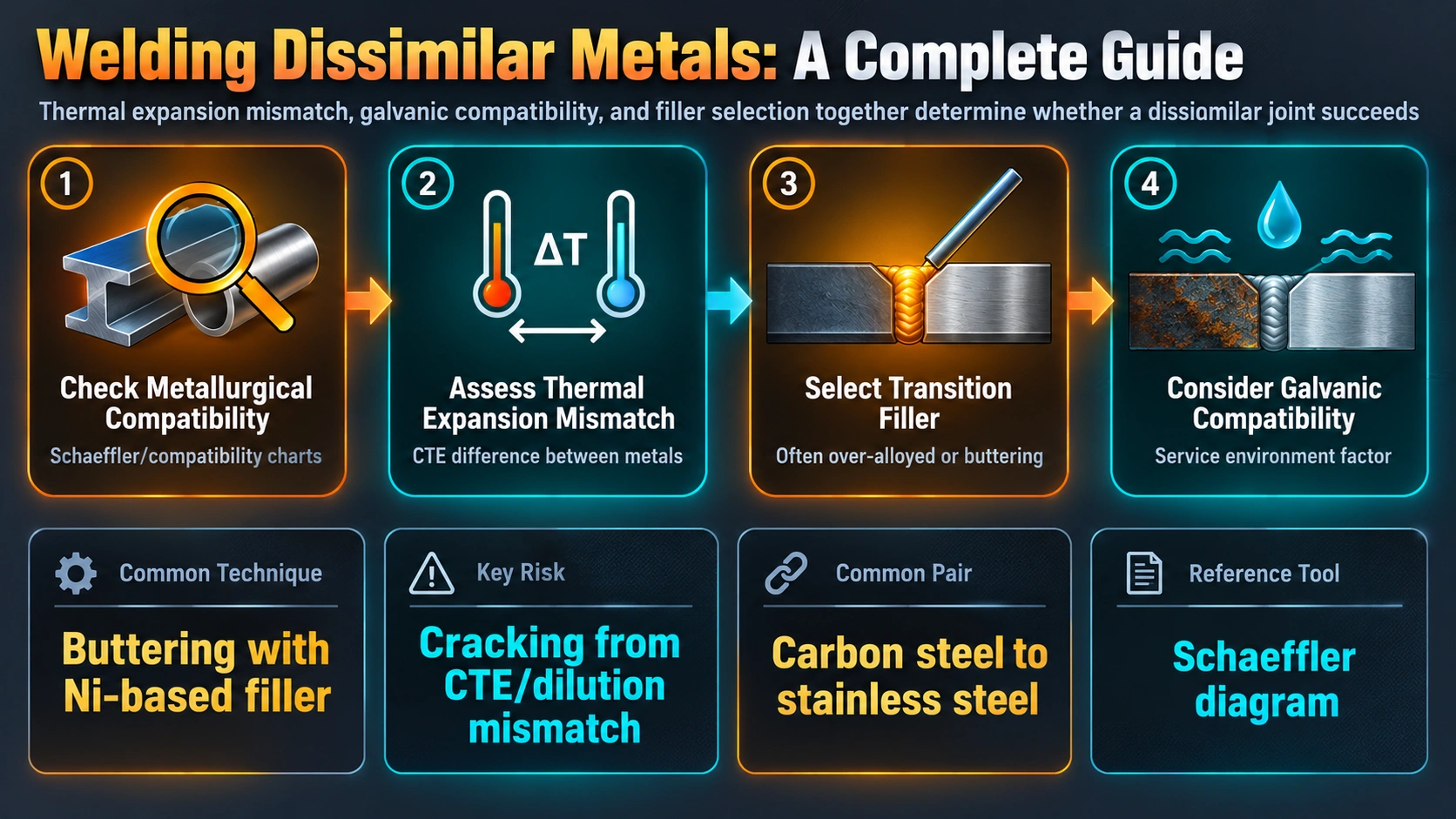
A similar-metal weld fails, when it fails, for reasons you would predict from the base metal alone – hydrogen cracking, lack of fusion, porosity. A dissimilar joint adds three failure modes that do not exist in similar welding at all.
Dilution changes the weld metal’s identity
Every arc welding pass melts some of both base metals into the filler. Dilution is calculated as the base metal contribution divided by the total weld metal, expressed as a percentage. If you weld carbon steel to stainless steel using ordinary stainless filler, the iron from the carbon steel side dilutes the chromium and nickel content of the pool enough that the resulting deposit can land in the brittle martensite region of a constitution diagram rather than the ductile austenitic region the filler was chosen for.
Brittle and low-melting phases at the fusion boundary
When two dissimilar alloys such as low-carbon steel and austenitic steel are fusion welded, the joints or heat-affected zones often exhibit low ductility and poor creep properties, since brittle martensite is more prone to form and the weld becomes more susceptible to hot cracking from low-melting impurities introduced by the carbon steel. An additional structure called an unmixed zone can form directly at the fusion line, where base metal melts and resolidifies without actually blending with the filler, sometimes producing hard, untempered martensite even inside an otherwise correctly-selected weld.
Galvanic corrosion risk
In a conductive environment, joining two metals with different electrochemical nobility creates a galvanic cell. The less noble metal becomes the anode and corrodes preferentially. A filler metal chosen only for mechanical compatibility can inadvertently become the anode relative to the surrounding base metals, concentrating corrosion into a thin weld bead – a very different, and often more dangerous, failure mode than uniform corrosion of a plate.
The Schaeffler and WRC-1992 Diagrams
Welding engineers do not guess when it comes to dissimilar metals; they use predictive diagrams. The Schaeffler diagram, and the more modern WRC-1992 diagram, plot chromium equivalent (ferrite-forming elements) against nickel equivalent (austenite-forming elements) to predict the microstructure of the finished weld.
By plotting the composition of the filler wire and the composition of the base metal and connecting them with a line, the resulting weld composition falls somewhere along that line depending on the dilution ratio. This lets an engineer confirm, before any welding happens, that the finished weld will land in a safe region of the diagram rather than the brittle martensite zone.
The golden rule of dissimilar welding, particularly for carbon steel to stainless steel, is to target a weld deposit that is primarily austenitic with a small amount of delta ferrite, typically 3 to 8 percent or 3 to 8 FN, since this structure is highly ductile and essentially immune to hot cracking. Too little ferrite and the weld becomes hot-crack sensitive; too much and toughness and corrosion resistance both suffer.
Filler Metal Selection by Combination
| Base Metal A | Base Metal B | Recommended Filler | Notes |
|---|---|---|---|
| Carbon steel | 304/304L stainless | ER309L / E309L | Standard |
| Carbon steel | 316/316L stainless | ER309LMo / E309LMo | Standard |
| Carbon/low-alloy steel | Duplex 2205 | Duplex filler (ER2209) or nickel filler | Verify phase balance |
| Stainless steel | Nickel alloy (Inconel/Hastelloy) | ERNiCrMo-3 (Alloy 625 filler) | Excellent tolerance to dilution |
| Carbon/low-alloy steel | Nickel alloy 600/625/690 | ERNiCr-3 or ERNiCrMo-3 | Standard buffer |
| P91/creep steel | Austenitic stainless | ERNiCr-3 (Alloy 82) buffer layer | Consider buttering |
Nickel-based filler alloys are commonly used in steel-to-stainless steel dissimilar metal welds because nickel’s high solubility for both iron and chromium keeps the weld deposit austenitic and ductile even at higher dilution levels than a stainless filler alone could tolerate. This is why ERNiCr-3 and ERNiCrMo-3 show up repeatedly across very different combinations – the underlying reason is the same each time.
AS/NZS 1554.6 lookup approach
Industry standards frequently simplify this into a direct lookup: carbon steel to 304(L) uses 309L filler, and carbon steel to 316(L) uses 309LMo filler. These pre-validated combinations are a reasonable starting point for common joints, but any combination outside a standard table should be checked with a constitution diagram rather than assumed safe.
Controlling Dilution in Practice
Dilution is primarily controlled by weld geometry and welding parameters; for a given filler metal feed rate, dilution increases with higher heat input. Practical dilution control techniques include:
- Process selection: GTAW gives the lowest, most controllable dilution and is the default choice for root passes on dissimilar joints; SAW and other high heat-input processes push dilution higher and need closer monitoring.
- Arc placement: The welding arc can be manipulated so it primarily impinges on the base metal nearest in composition to the filler, reducing dilution from the more dissimilar side of the joint.
- Arc drift toward steel: When joining nickel-base alloys to carbon or low-alloy steels, the arc may tend to drift toward the steel side, so short arc length and careful torch or electrode manipulation are needed to compensate.
- Multi-layer buildup: Building up the first layer or two with lower current before increasing deposition rate on fill passes limits how much of the dissimilar base metal enters the final weld composition.
The Buttering Technique
Buttering solves a specific problem: two base metals that each need a different, sometimes incompatible, heat treatment. A layer of compatible filler metal is deposited onto the more demanding side (commonly a low-alloy or creep steel requiring PWHT) and that buttered layer is heat treated on its own before the dissimilar joint is finally completed and welded together.
Practical tip: Buttering is especially valuable when a P91 or other creep-strength enhanced ferritic steel nozzle must transition into an austenitic or nickel-clad vessel. The steel side gets its full required PWHT while buttered, and the final assembly weld to the stainless or nickel side never needs to subject the completed dissimilar joint to a heat treatment it does not need or tolerate well.
Galvanic Compatibility
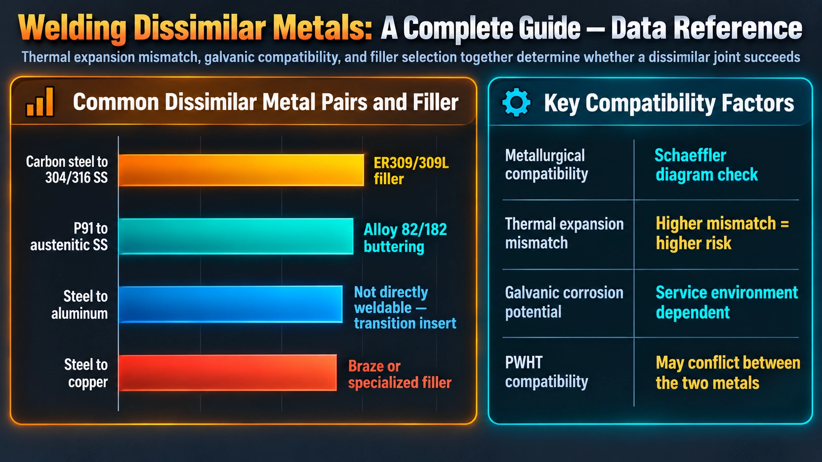
Beyond metallurgical compatibility in the as-welded structure, dissimilar joints in wet, humid, or immersed service need a galvanic check. Selecting a filler that sits close to the more noble of the two base metals on the galvanic series, rather than close to the less noble one, avoids concentrating corrosion attack into the weld bead itself.
Common mistake: Choosing a filler purely for mechanical strength or ease of welding, without checking its position on the galvanic series relative to both base metals, can turn an otherwise sound joint into the sacrificial anode of the whole structure – a failure mode that has nothing to do with weld quality and everything to do with electrochemistry.
Inspection Considerations for Dissimilar Joints
- Hardness surveys: A hardness traverse across the fusion boundary confirms no untempered martensite or unmixed zone formed at unacceptable hardness levels.
- Ferrite number checks: On stainless-to-steel joints, a ferrite number check (magnetic gauge or metallographic point count) confirms the weld deposit landed in the targeted 3-8 FN window rather than drifting into a brittle or corrosion-prone extreme.
- Volumetric and surface NDT: Radiography or UT per the governing code, supplemented with liquid penetrant testing, since fine cracking at the fusion boundary can be easy to miss on radiographs alone.
- Corrosion testing: Where service is aggressive, ASTM G48-type testing can confirm the actual weld deposit chemistry delivers the corrosion resistance the diagram-based prediction assumed.
Amazon Recommended References
Welding Metallurgy
Sindo Kou’s core reference on dilution, constitution diagrams and dissimilar metal weldability.
View on AmazonMetals and How to Weld Them
Practical filler selection guidance across ferrous and non-ferrous base metal combinations.
View on AmazonASM Handbook: Welding, Brazing and Soldering
Covers dissimilar metal joining processes, filler selection tables and metallurgical background.
View on AmazonCorrosion Engineering Handbook
Galvanic series data and corrosion prediction methods relevant to dissimilar joint design.
View on AmazonDisclosure: WeldFabWorld participates in the Amazon Associates programme (StoreID: neha0fe8-21). If you purchase through these links, we may earn a small commission at no extra cost to you. This helps support free technical content on this site.
Frequently Asked Questions
What filler metal is used to weld carbon steel to stainless steel?
ER309L or E309L is the standard filler for joining carbon or low-alloy steel to 304/304L stainless steel, and ER309LMo/E309LMo is used when the stainless side is 316/316L. These fillers carry enough chromium and nickel that even after dilution from the carbon steel side, the resulting weld metal still lands in the austenite-plus-ferrite region of the Schaeffler diagram rather than the brittle martensite region.
What is the Schaeffler diagram used for in dissimilar welding?
The Schaeffler diagram plots chromium equivalent against nickel equivalent to predict the room-temperature microstructure of a weld deposit formed from a mix of base metals and filler. By plotting each material’s position and drawing a dilution line between them, a welding engineer can confirm the final weld composition lands in a safe, ductile region rather than a brittle martensitic zone before any welding actually happens.
How much dilution should be assumed when welding dissimilar metals?
A common planning assumption for standard open-arc processes is roughly 30 percent dilution from the combined base metals and 70 percent from the filler metal, though this varies with joint design, welding process and technique. Submerged arc and high heat-input processes can push dilution significantly higher, which is why root passes on dissimilar joints are often made with GTAW specifically to keep dilution low and controllable.
Why does galvanic corrosion matter when welding dissimilar metals?
When two dissimilar metals are electrically connected in a conductive environment, the less noble metal becomes the anode and corrodes preferentially to protect the more noble metal. Filler metal selection should avoid creating a weld deposit that is anodic relative to the surrounding base metals, since concentrating that corrosion attack into a narrow weld bead can cause premature, localized failure even when the joint was mechanically sound as welded.
What is the buttering technique in dissimilar metal welding?
Buttering means depositing a layer of compatible filler metal onto one base metal face and heat treating that buttered layer before the final joint is completed. It is commonly used when joining a low-alloy steel requiring PWHT to an austenitic stainless or nickel alloy that does not need or tolerate the same heat treatment, letting each side receive the thermal treatment it actually requires.
Can carbon steel be welded directly to duplex stainless steel?
Yes, typically using a duplex or super-duplex filler metal, or in some cases a nickel-based filler, selected via the Schaeffler or WRC-1992 diagram to confirm the resulting weld deposit retains an appropriate austenite-to-ferrite balance. Getting the dilution wrong on this joint risks either excess ferrite, which reduces toughness and corrosion resistance, or excess austenite, which loses the strength duplex grades are chosen for.
Why do nickel-based fillers work well for most dissimilar metal joints?
Nickel has very high solubility for both iron and chromium, so a nickel-rich weld deposit stays austenitic and ductile even after significant dilution from a ferritic or martensitic base metal. This tolerance for dilution is why nickel fillers such as ERNiCr-3 and ERNiCrMo-3 are the default choice for joints that would otherwise be difficult to predict on a Schaeffler diagram, particularly steel-to-superalloy transitions.