Narrow Gap Welding Technique Explained
Narrow gap welding is a thick-section joining technique that replaces the wide V-groove of conventional multi-pass welding with a nearly parallel-sided groove only marginally wider than the welding wire or torch itself, cutting filler metal consumption and welding time dramatically on heavy wall pipe, pressure vessel, and nuclear components. By minimizing groove volume, narrow gap welding directly attacks the two biggest cost drivers of thick section welding, filler metal and arc-on time, while also reducing total heat input and the resulting distortion across the finished joint.
This guide explains how narrow gap grooves are designed and machined, the specialized torch and wire delivery systems the process demands to reach the base of a deep, confined groove, the process variants used in submerged arc and GTAW narrow gap welding, the defects unique to welding inside such a tight space, and where the process earns its equipment and tooling investment against conventional wide-groove multi-pass welding using processes such as SAW and GTAW.
Whether you are specifying joint preparation for a heavy wall pressure vessel shell, comparing narrow gap SAW against conventional multi-pass welding for a large diameter pipeline, or qualifying a procedure under ASME Section IX, this article gives you the working technical foundation to evaluate the process.
How Narrow Gap Welding Reduces Weld Volume
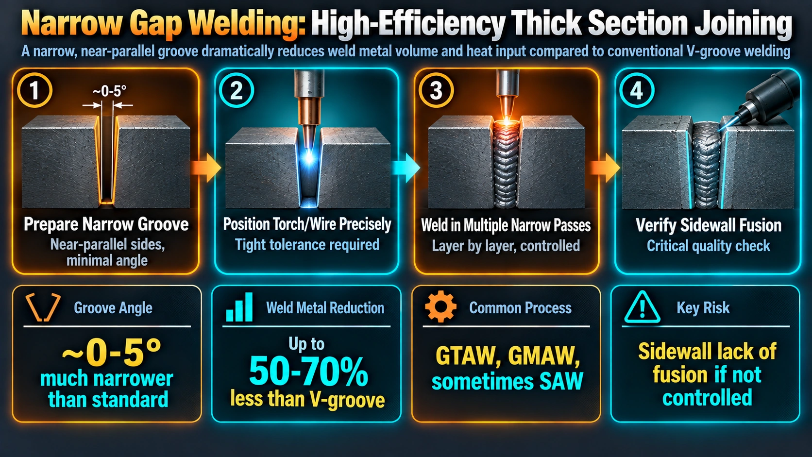
A conventional single-V groove on a 50 mm thick plate, with a typical included angle of 60 degrees, requires a root opening that widens to well over 50 mm at the cap pass, meaning the great majority of the joint cross section must be filled with weld metal, pass after pass, across the full width of that wide V. A narrow gap groove for the same 50 mm thickness instead holds a nearly constant width of roughly 8 mm to 16 mm from root to cap, since the groove sidewalls are cut almost parallel to each other rather than flaring outward.
Because the cross-sectional area to be filled scales directly with groove width, cutting the average groove width by a factor of three to five, which is typical of narrow gap versus conventional V-groove design, cuts filler metal volume and arc-on time by roughly the same factor for the same plate thickness. This single geometric change is the entire economic and technical case for narrow gap welding.
Groove design tolerances
Because the groove is so narrow, machining tolerances on groove width, sidewall angle, and straightness must be tighter than for a conventional wide V-groove. A groove that opens or narrows unexpectedly along its length leaves the arc unable to consistently reach and fuse both sidewalls, which is the root cause of the process’s signature defect.
Torch and Wire Delivery Systems
Reaching the base of a deep, narrow groove with a conventional torch or wire guide is not physically possible once the groove depth exceeds a small multiple of its width, which is why narrow gap welding equipment uses specialized long, slender torch or wire delivery heads, often with side-shielded or laterally offset contact tips, that can be lowered into the groove without contacting the sidewalls above the current weld pass.
Arc oscillation and sidewall targeting
Because the groove leaves almost no room for a wide weave pattern, narrow gap systems typically use small-amplitude mechanical or electromagnetic oscillation to sweep the arc between the two sidewalls on a controlled cycle, dwelling briefly at each sidewall to ensure fusion before moving to the opposite side. Some systems instead use twin-wire or twin-torch configurations, with one arc directed at each sidewall, to eliminate the need for oscillation entirely.
Narrow Gap Process Variants
Narrow gap submerged arc welding (NG-SAW)
Adapts submerged arc welding to a narrow groove using specialized flux delivery and wire guide nozzles, and is widely used on heavy wall pressure vessel and thick pipe circumferential seams where SAW’s high deposition rate and mechanized nature suit long production runs.
Narrow gap GTAW (NG-GTAW)
Adapts GTAW to a narrow groove, often with hot-wire feed to increase deposition rate beyond what cold-wire GTAW alone would achieve, and is favored where weld quality and low defect tolerance justify GTAW’s process control even at its lower deposition rate compared with SAW.
Narrow gap GMAW and hybrid processes
Narrow gap adaptations of GMAW and hybrid laser-arc systems are used less commonly but offer higher deposition rates than GTAW in applications where GMAW’s spatter and fusion characteristics can be adequately controlled within the confined groove.
| Process Variant | Deposition Rate | Quality Control | Typical Application |
|---|---|---|---|
| NG-SAW | High | Good, mechanized | Heavy wall pressure vessels, thick pipe |
| NG-GTAW (incl. hot-wire) | Low to moderate | Excellent | Nuclear, critical service, high-alloy steels |
| NG-GMAW / hybrid | Moderate to high | Requires tight control | General thick section fabrication |
Defects Unique to Narrow Gap Welding
Lack of sidewall fusion
The process’s signature defect occurs when the arc fails to adequately fuse to one or both groove sidewalls, most often from incorrect arc positioning, insufficient oscillation amplitude, or arc wander within the confined groove. Because there is very little visible groove opening to inspect during welding, lack of sidewall fusion is controlled through precise mechanized arc guidance and parameter discipline rather than through visual monitoring, and it is typically verified only through volumetric non-destructive testing after welding.
Slag entrapment (NG-SAW)
In narrow gap submerged arc welding, incomplete slag removal between passes in the confined groove space is more likely than in a wide groove, since there is less room to manipulate a grinder or chipping tool between layers.
Incomplete fill / lack of interpass cleaning
The tight groove geometry that gives narrow gap welding its efficiency also makes interpass cleaning and visual inspection between passes physically more difficult than in a conventional wide groove, increasing the importance of a disciplined, well-documented welding sequence.
Narrow Gap Welding Compared with Conventional Multi-Pass Welding
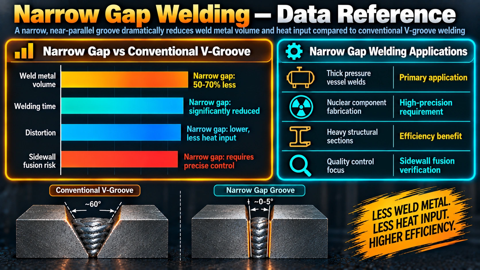
| Characteristic | Narrow Gap Welding | Conventional Wide V-Groove |
|---|---|---|
| Filler metal volume (thick section) | Much lower | High |
| Welding time (thick section) | Much lower | High |
| Total heat input / distortion | Lower | Higher |
| Joint preparation tolerance | Tight | More forgiving |
| Equipment / tooling investment | Higher (specialized) | Standard equipment |
| Sidewall fusion risk | Process-specific concern | Lower risk (wide access) |
Applications of Narrow Gap Welding
Narrow gap welding is used almost exclusively on thick section work where the filler metal and time savings justify the specialized equipment and tighter joint preparation control it demands.
Power generation and nuclear
Heavy wall reactor pressure vessel and steam generator shell welds, often in low-alloy and stainless steels many tens to hundreds of millimeters thick, are a classic narrow gap welding application where both cost and weld quality requirements are extreme.
Petrochemical and pressure vessel fabrication
Thick wall pressure vessel shell and head-to-shell circumferential seams use narrow gap SAW to keep welding time and consumable cost manageable on large-diameter, heavy-wall equipment.
Pipeline and heavy pipe fabrication
Large diameter, thick wall pipe girth welds in offshore and high-pressure pipeline applications increasingly use narrow gap welding to reduce the very large filler volume that conventional wide-groove welding would otherwise require on thick wall pipe.
Frequently Asked Questions
What is narrow gap welding?
Which welding processes are used for narrow gap welding?
What is lack of sidewall fusion in narrow gap welding?
Why does narrow gap welding reduce distortion compared with conventional welding?
What thickness range is narrow gap welding typically used for?
Does narrow gap welding require special joint preparation?
What are the main advantages of narrow gap welding over conventional V-groove welding?
Recommended Reading
Submerged Arc Welding Handbook
Reference on SAW process fundamentals, equipment, and adaptation to narrow gap groove designs.
View on AmazonWelding Handbook (AWS), Volume on Welding Processes
Broad process reference covering narrow gap variants of SAW and GTAW alongside conventional groove welding.
View on AmazonPressure Vessel Design Handbook
Reference on heavy wall pressure vessel design and fabrication where narrow gap welding is commonly specified.
View on AmazonWelding Metallurgy (Kou)
Covers heat input, distortion, and residual stress fundamentals relevant to narrow gap versus conventional groove welding.
View on AmazonDisclosure: WeldFabWorld participates in the Amazon Associates programme (StoreID: neha0fe8-21). If you purchase through these links, we may earn a small commission at no extra cost to you. This helps support free technical content on this site.