Resistance Spot Welding — Process, Parameters, Defects
Resistance spot welding is a solid-and-liquid-state joining process that fuses overlapping sheet metal at discrete points by passing a high electrical current through the stacked sheets under electrode force, generating heat through the metal’s own electrical resistance rather than from an arc or flame. It remains the dominant joining method for automotive body-in-white assembly and general sheet metal fabrication because a single spot weld can be completed in a fraction of a second, needs no filler metal or shielding gas, and lends itself completely to robotic automation.
This guide covers how the weld nugget actually forms at the faying surface between two sheets, the three governing schedule variables of current, time, and force, electrode geometry and wear, the defects specific to a resistance process such as expulsion and undersized nuggets, and how spot welding compares with fusion arc processes such as GMAW for thin sheet assembly.
Whether you are troubleshooting inconsistent nugget size on a production line, developing a weld schedule for a new coated steel grade, or simply want to understand why spot welding dominates high-volume sheet metal assembly, this article gives you the working technical foundation.
How Resistance Spot Welding Works
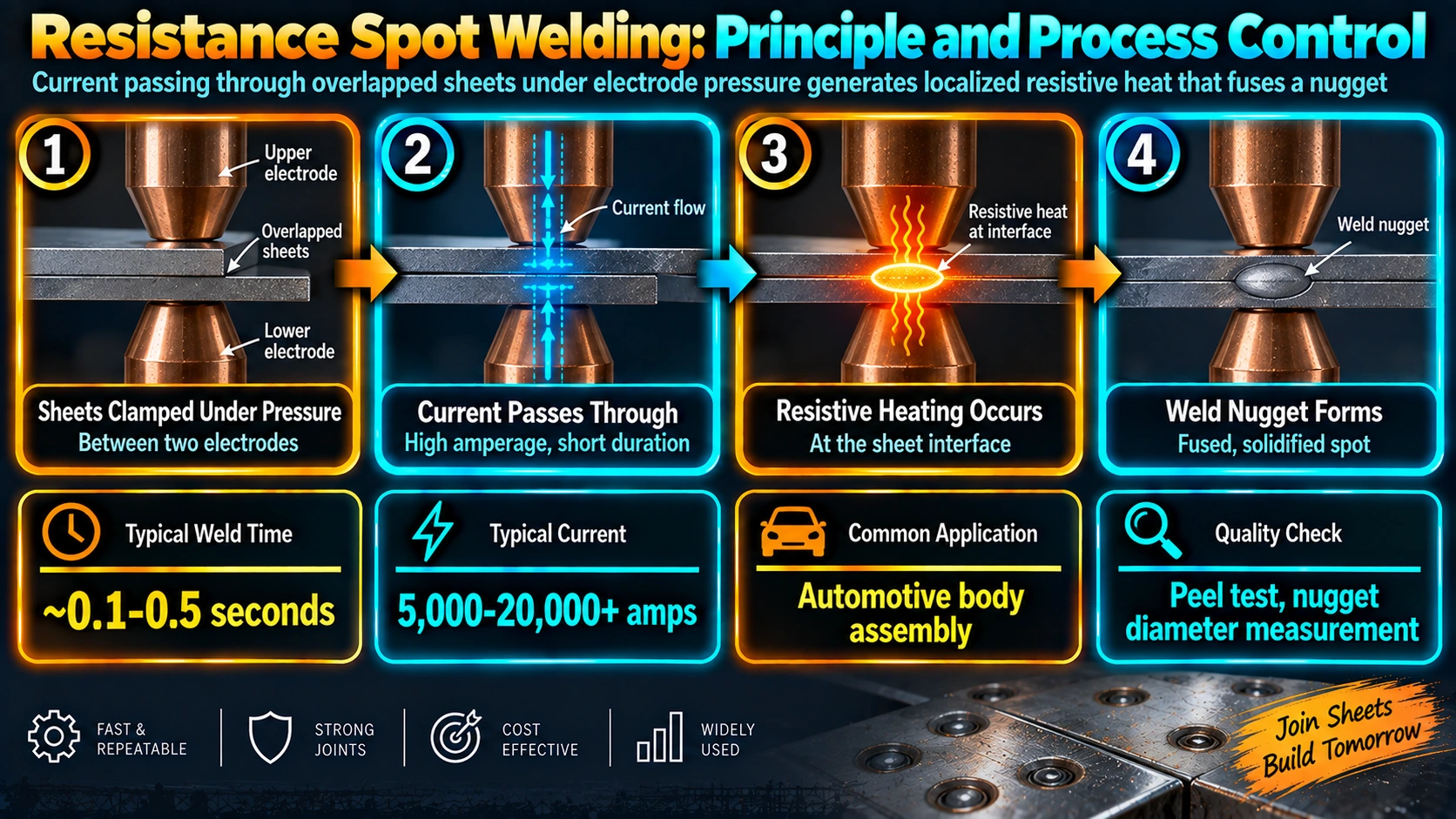
Two copper alloy electrodes clamp overlapping sheets together under a controlled force. A high welding current, typically several thousand amperes at only a few volts, is passed through the electrodes and the sheet stack for a precisely timed interval, usually a fraction of a second to a few seconds depending on material and thickness. Electrical resistance is not uniform through the stack: it is highest at the interface between the two sheets, called the faying surface, because that is where surface roughness and any coating create the greatest contact resistance.
Heat generated at the faying surface raises the local temperature to melting, forming a lens-shaped pool of molten metal, the weld nugget, that grows outward and slightly upward and downward from the interface as welding continues. Once current stops, the electrodes continue applying force for a brief hold time while the nugget solidifies under pressure, which is essential to producing a sound, void-free weld.
The Three Governing Weld Schedule Variables
Weld current
Sets the rate of heat generation according to the resistive heating relationship. Current is the most sensitive variable in the schedule; small changes produce large changes in nugget size because heat generation scales with the square of current.
Weld time
The duration current flows, usually specified in cycles of the AC power supply (60 cycles per second in a 60 Hz system, 50 in a 50 Hz system) or in milliseconds for inverter-based DC equipment. Longer weld time increases total heat input and nugget growth up to the point where excessive time risks expulsion or electrode indentation.
Electrode force
The clamping force applied through the electrodes, which controls contact resistance at both the electrode-to-sheet and sheet-to-sheet interfaces and resists the internal pressure of the molten nugget. Force that is too low increases contact resistance unpredictably and raises expulsion risk; force that is too high suppresses contact resistance so much that insufficient heat is generated for the given current and time.
Electrode Design and Wear
Spot welding electrodes are made from copper alloys, most commonly copper-chromium or copper-zirconium, chosen for a balance of high electrical and thermal conductivity with enough mechanical strength and hardness to resist deformation under repeated force and heat cycles. Tip geometry, typically a truncated cone, dome, or radius face, is selected based on sheet thickness, coating, and accessibility.
Electrode tips gradually mushroom, meaning the tip face flattens and enlarges, from the combined effects of mechanical force, heat, and, on coated steels, alloying between the zinc coating and the copper electrode surface. As the tip face enlarges, current density drops for a fixed current setting, which reduces heat input and eventually produces undersized nuggets unless the weld schedule is adjusted or the electrode is redressed or replaced.
| Electrode Issue | Typical Cause | Effect on Weld |
|---|---|---|
| Mushrooming (tip growth) | Repeated thermal/mechanical cycling | Undersized nugget over time |
| Zinc pickup / alloying | Welding galvanized steel | Accelerated tip wear, resistance variation |
| Misalignment | Worn holders, bent shanks | Asymmetric nugget, expulsion at edge |
| Insufficient cooling water flow | Blocked or undersized cooling circuit | Accelerated softening and mushrooming |
Common Resistance Spot Welding Defects
Expulsion
Expulsion occurs when internal pressure from rapidly generated molten metal exceeds the electrode force holding the sheets together, spraying molten metal from the faying surface or the electrode-to-sheet interface. It is most often caused by excessive current or time relative to force, or by insufficient force for the current level, and it typically leaves a visibly undersized or irregular nugget behind.
Undersized nugget
Insufficient heat input, whether from low current, short weld time, worn electrodes, or excessive shunting through an adjacent weld, produces a nugget below the minimum diameter needed to meet strength requirements, even though the weld may look acceptable from the surface.
Stick weld / cold weld
A stick weld occurs when the sheets bond without forming a true fused nugget, often from severely insufficient current or a heavily contaminated or oxidized faying surface. It can appear satisfactory visually and even pass a light peel test while failing under real service load.
Electrode indentation and surface marking
Excessive force or weld time can leave a visible depression from the electrode tip on the sheet surface, which matters for cosmetic outer body panels even when the weld itself is structurally sound.
Applications of Resistance Spot Welding
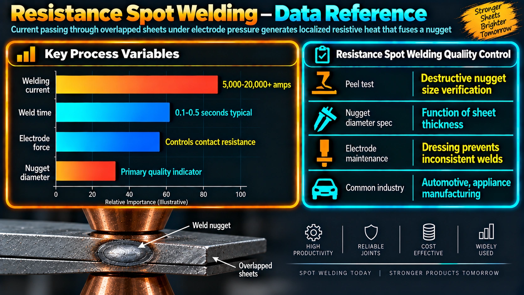
Automotive body assembly
A typical automotive body-in-white contains several thousand spot welds joining stamped sheet steel and increasingly aluminum panels, making RSW the backbone of high-volume vehicle assembly lines and a heavily automated, robot-driven process.
Appliance and general sheet metal fabrication
Household appliance cabinets, HVAC ductwork, and general sheet metal enclosures use spot welding wherever overlapping thin sheet joints need fast, consumable-free assembly without the distortion that arc welding introduces on thin material.
Structural sheet applications
Cold-formed steel structural framing and light structural assemblies use spot welding where the code and design allow it as an alternative to mechanical fasteners, offering faster assembly and a cleaner finished appearance.
Frequently Asked Questions
How does resistance spot welding create a weld nugget?
What are the three main variables in a resistance spot welding schedule?
What causes expulsion in spot welding?
How is spot weld nugget size checked in production?
Why do spot welding electrodes wear out?
Can resistance spot welding join galvanized steel?
What is the difference between resistance spot welding and resistance seam welding?
Recommended Reading
Resistance Welding: Fundamentals and Applications
Reference text on resistance welding process physics, equipment, and schedule development.
View on AmazonWelding Handbook (AWS), Volume on Welding Processes
Broad process reference including resistance welding alongside arc and beam processes for comparison.
View on AmazonSheet Metal Forming and Fabrication Handbook
Practical reference on sheet metal assembly methods including spot welding in production fabrication.
View on AmazonWelding Metallurgy (Kou)
Covers rapid solidification and heat-affected zone effects relevant to resistance spot weld nuggets.
View on AmazonDisclosure: WeldFabWorld participates in the Amazon Associates programme (StoreID: neha0fe8-21). If you purchase through these links, we may earn a small commission at no extra cost to you. This helps support free technical content on this site.