Friction Stir Welding Explained
Friction Stir Welding is a solid-state joining process that produces a full-strength weld without ever melting the base metal, using nothing more than a rotating tool, downward force, and controlled travel speed to plasticize and mechanically stir the joint line together. Because the peak temperature stays well below the melting point, FSW sidesteps the solidification cracking, porosity, and heat-affected zone softening that make fusion welding of high-strength aluminum alloys so difficult, which is exactly why the process was invented for aerospace and marine aluminum structures and has since spread into steel, copper, and dissimilar metal applications.
This guide covers how the FSW tool and process actually generate a joint, the shoulder and pin geometry choices that control material flow, the key process parameters an engineer must set, the defects unique to a process that never melts anything, and where FSW earns its place against conventional fusion processes such as GMAW and GTAW.
Whether you are evaluating FSW for an aluminum panel line, qualifying a procedure that references ASME Section IX, or simply trying to understand why a process with no arc, no filler metal, and no shielding gas can still be called welding, this article gives you the working technical foundation.
How Friction Stir Welding Works
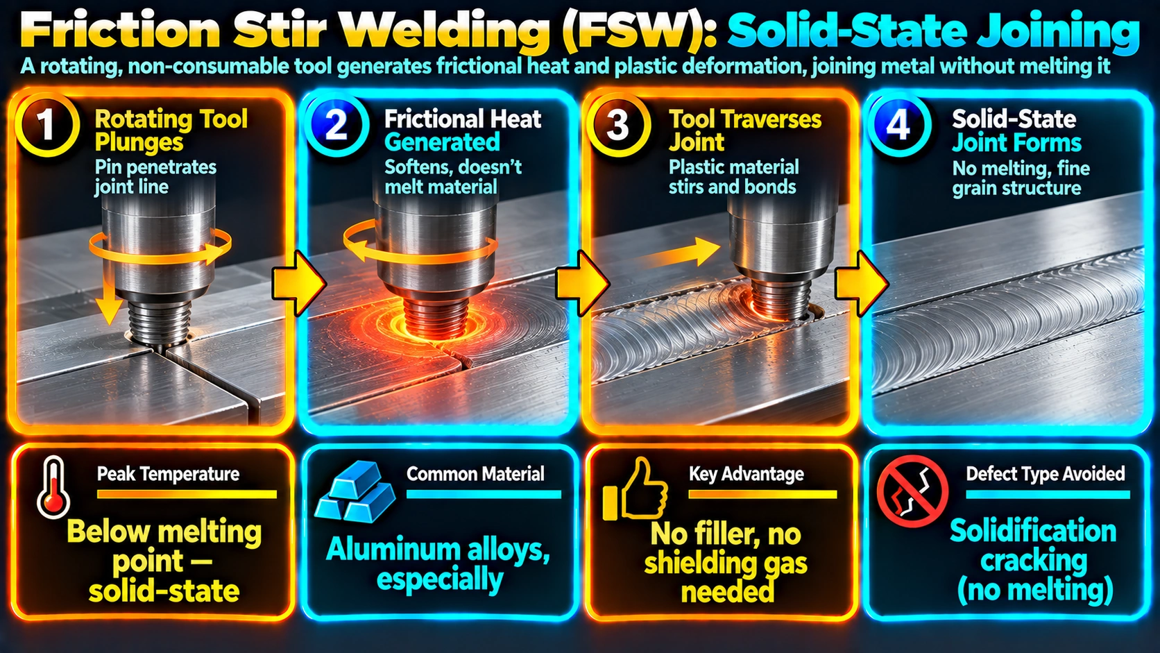
A non-consumable rotating tool, consisting of a shoulder and a protruding pin, is plunged into the abutting edges of two workpieces that are rigidly clamped against a backing anvil. Friction between the rotating shoulder and the workpiece surface, combined with severe plastic deformation from the pin, heats the material to a plasticized, dough-like state, typically 70 percent to 90 percent of the base metal’s absolute melting temperature, without ever reaching the melting point itself.
Once the tool reaches this plasticized state at the plunge location, it translates along the joint line at a controlled travel speed. Material is swept from the leading edge of the pin, around the tool, and deposited at the trailing edge under the forging pressure of the shoulder, mechanically stitching the two sides of the joint into a single continuous piece of metal. The shoulder simultaneously contains the plasticized material against escaping upward and provides most of the frictional heat input, while the pin does the mechanical stirring that actually consolidates the joint through its full thickness.
Advancing side and retreating side
Because the tool rotates while also translating, one side of the joint has the tool’s surface velocity adding to the travel direction (the advancing side), while the other side has it subtracting (the retreating side). This asymmetry produces a characteristic asymmetric weld nugget and is the reason FSW procedures specify tool rotation direction relative to the joint, not just rotation speed.
Tool Design: Shoulder and Pin Geometry
The FSW tool is arguably the single most important variable in the process, since its geometry directly controls how material flows and consolidates.
Shoulder design
The shoulder contacts the top surface of the workpiece, generates the majority of the frictional heat, and applies the downward forging force that consolidates the plasticized material. Shoulders are commonly machined with concave faces, scrolled features, or concentric grooves to help draw plasticized material inward and prevent it from being expelled as flash.
Pin (probe) design
The pin penetrates to nearly the full depth of the joint and does the mechanical stirring that consolidates material through the thickness. Threaded pins, flatted pins, and fluted pins are all used to promote vertical material flow; the pin length is set to leave a small standoff from the backing anvil, since a pin that contacts the anvil directly will wear rapidly and can damage the anvil surface.
| Tool Feature | Primary Function | Design Notes |
|---|---|---|
| Shoulder diameter | Heat generation, surface consolidation | Typically 2.5 to 3 times the pin diameter |
| Shoulder profile | Contain and direct plasticized flash | Concave, scrolled, or featured for containment |
| Pin length | Sets penetration depth | Critical — standoff from anvil required |
| Pin thread/flute | Vertical material transport | Direction matched to rotation for correct flow |
| Tool material | Wear resistance at process temperature | Tool steel (Al alloys); PCBN, W-Re (steel) |
Key FSW Process Parameters
Tool rotational speed
Controls the rate of frictional heat generation. Higher rotational speed increases heat input and material plasticization but excessive speed can overheat the joint and coarsen the recrystallized grain structure in the weld nugget.
Travel (welding) speed
The rate at which the tool moves along the joint. Slower travel speed increases heat input per unit length; faster travel speed reduces it but risks insufficient plasticization if pushed too far for a given rotational speed.
Tool tilt angle
A small tilt, typically 1 to 3 degrees, of the tool axis opposite to the travel direction helps the shoulder forge and consolidate material at the trailing edge rather than simply riding over the surface.
Plunge force / axial force
The downward force applied through the tool, which must be sufficient to maintain full shoulder contact and pin penetration throughout the weld without over-thinning the joint from excessive plunge depth.
Defects Unique to Friction Stir Welding
Kissing bond
A kissing bond occurs when the two sides of the joint are pressed together under the tool’s forging force but do not achieve true metallurgical bonding, often due to insufficient pin penetration or an oxide layer that is not adequately broken up and dispersed. Because there is no volumetric gap, kissing bonds are notoriously difficult to detect with conventional radiography and usually require bend testing or specialized ultrasonic techniques during qualification.
Wormhole (tunnel) defect
An internal void running along the weld, usually caused by insufficient heat input or incorrect pin geometry preventing enough material from flowing to fill the space behind the advancing pin. It is controlled through parameter adjustment rather than repair welding, since there is no fusion zone to repair with filler metal.
Surface lack of fill and flash
Insufficient forging force or an incorrect plunge depth can leave a groove-like surface lack of fill along the weld centerline, while excessive plunge depth or force produces excessive flash extruded from the sides of the shoulder.
Exit hole
At the end of a standard FSW pass, withdrawing the tool leaves a keyhole-shaped hole the size of the pin, which is unacceptable in most pressure-retaining or structural applications unless run-off tabs are used or a retractable-pin tool closes the hole in place.
FSW Compared with Fusion Welding
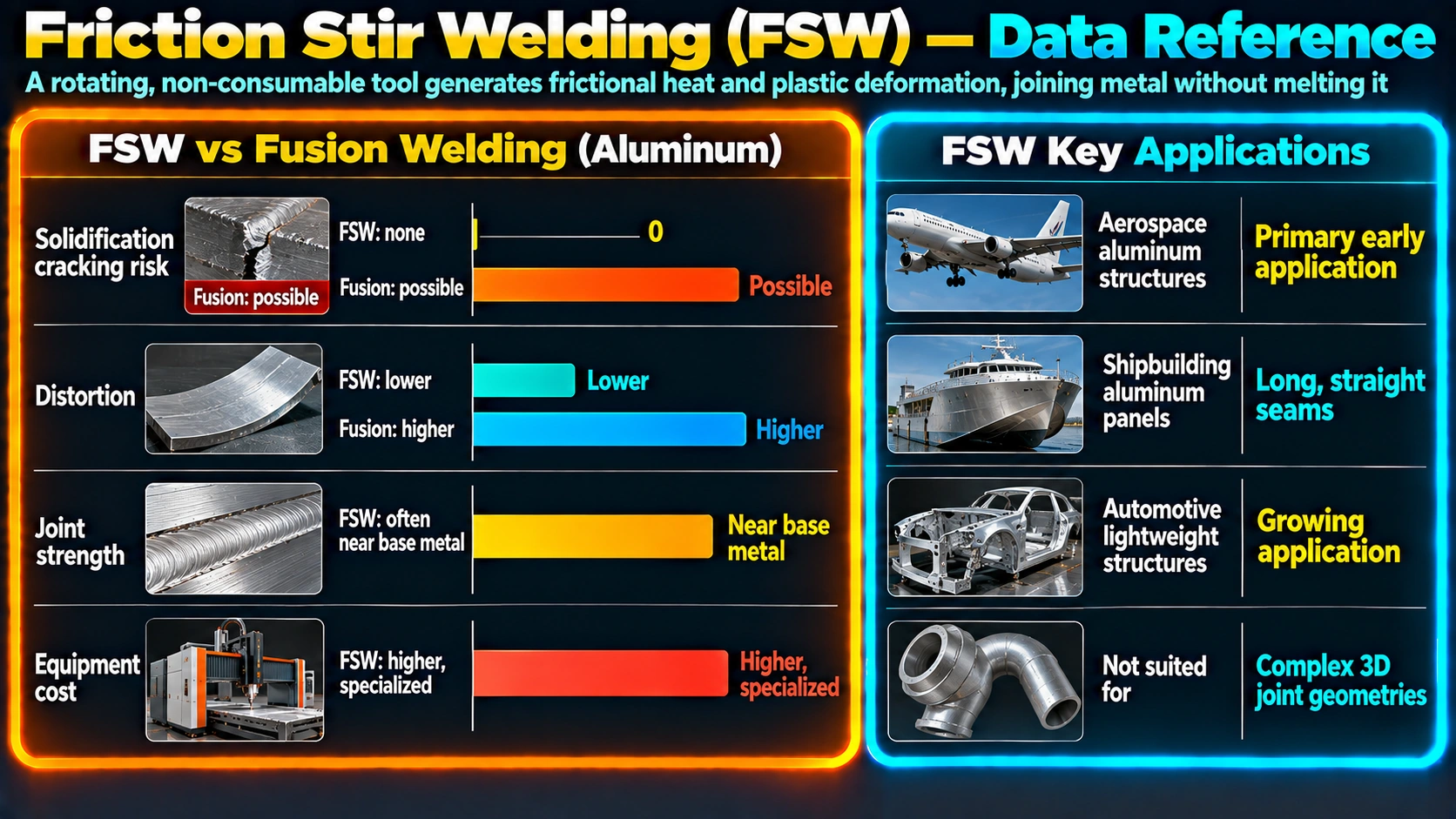
Because FSW never melts the base metal, it avoids an entire category of defects and metallurgical problems that affect arc and beam fusion processes, but it introduces its own constraints.
| Characteristic | FSW | GMAW (Fusion) | GTAW (Fusion) |
|---|---|---|---|
| Base metal melting | None (solid state) | Yes | Yes |
| Solidification cracking risk | Eliminated | Present | Present |
| Filler metal / shielding gas | Not required | Required | Required |
| Distortion | Low | Moderate to high | Moderate |
| Fixturing / clamping needs | High (rigid + anvil) | Low to moderate | Low to moderate |
| Joint geometry flexibility | Limited (mainly linear butt/lap) | High | High |
| Best suited materials | Al, Cu, Mg, some steel/Ti | Wide range | Wide range |
Applications of Friction Stir Welding
Aerospace and rail
FSW is used extensively for aluminum fuselage panels, launch vehicle propellant tanks, and rail car structural extrusions, where the elimination of solidification cracking in high-strength 2xxx and 7xxx aluminum alloys is a decisive advantage over fusion welding.
Marine and shipbuilding
Aluminum hull panels, deck structures, and marine extrusions benefit from FSW’s low distortion, which reduces the fairing and straightening work required after fabrication compared with fusion-welded panels.
Automotive
Aluminum body panels, battery enclosures for electric vehicles, and heat exchanger assemblies use FSW for its consistent, high-volume-compatible weld quality without consumable costs.
Dissimilar metal joints
Because FSW never forms a conventional fusion zone, it can join combinations that are essentially unweldable by arc processes, including aluminum to steel and aluminum to copper, by mechanically interlocking the two metals rather than mixing them in a molten pool.
Frequently Asked Questions
Is Friction Stir Welding a fusion welding process?
What metals can be joined by Friction Stir Welding?
What is a kissing bond defect in FSW?
Why doesn’t Friction Stir Welding need filler metal or shielding gas?
What are the main FSW tool components?
Can Friction Stir Welding be used on steel?
How does FSW compare with fusion welding for aluminum?
Recommended Reading
Friction Stir Welding and Processing
Reference text on FSW process physics, tool design, and metallurgy across aluminum, steel, and dissimilar metal applications.
View on AmazonWelding Metallurgy (Kou)
Covers recrystallization, grain structure, and solid-state joining fundamentals relevant to FSW nugget formation.
View on AmazonASM Handbook: Welding, Brazing, and Soldering
Reference volume with a dedicated section on friction stir welding process parameters and defects.
View on AmazonAluminum Design and Fabrication Handbook
Practical reference on aluminum alloy selection and fabrication methods including solid-state joining.
View on AmazonDisclosure: WeldFabWorld participates in the Amazon Associates programme (StoreID: neha0fe8-21). If you purchase through these links, we may earn a small commission at no extra cost to you. This helps support free technical content on this site.