Stud Welding Process and Applications
Stud welding is an arc welding process that attaches a threaded, headed, or plain metal stud to a base plate in a single automatic operation lasting well under a second, making it one of the fastest fastener-attachment methods available to fabricators. Instead of a welder manually running a fillet weld around a pre-placed fastener, a stud welding gun holds the stud, strikes a controlled arc between the stud tip and the base plate, and then plunges the stud into the resulting molten pool under spring or pneumatic force, forging a full-strength weld with no filler metal and virtually no operator skill variability.
This guide explains the two dominant stud welding methods, drawn arc and capacitor discharge, the role of the ceramic ferrule, the key process parameters, the defects a fabricator needs to watch for, and where stud welding earns its place in structural steel, shipbuilding, and sheet metal fabrication. Comparisons are grounded against manual processes such as SMAW so the tradeoffs are concrete.
Whether you are specifying shear connectors for a composite steel-concrete deck under code-governed structural work, or simply trying to choose between drawn arc and capacitor discharge for a sheet metal cabinet, this article gives you the working knowledge to make that call.
How Stud Welding Works
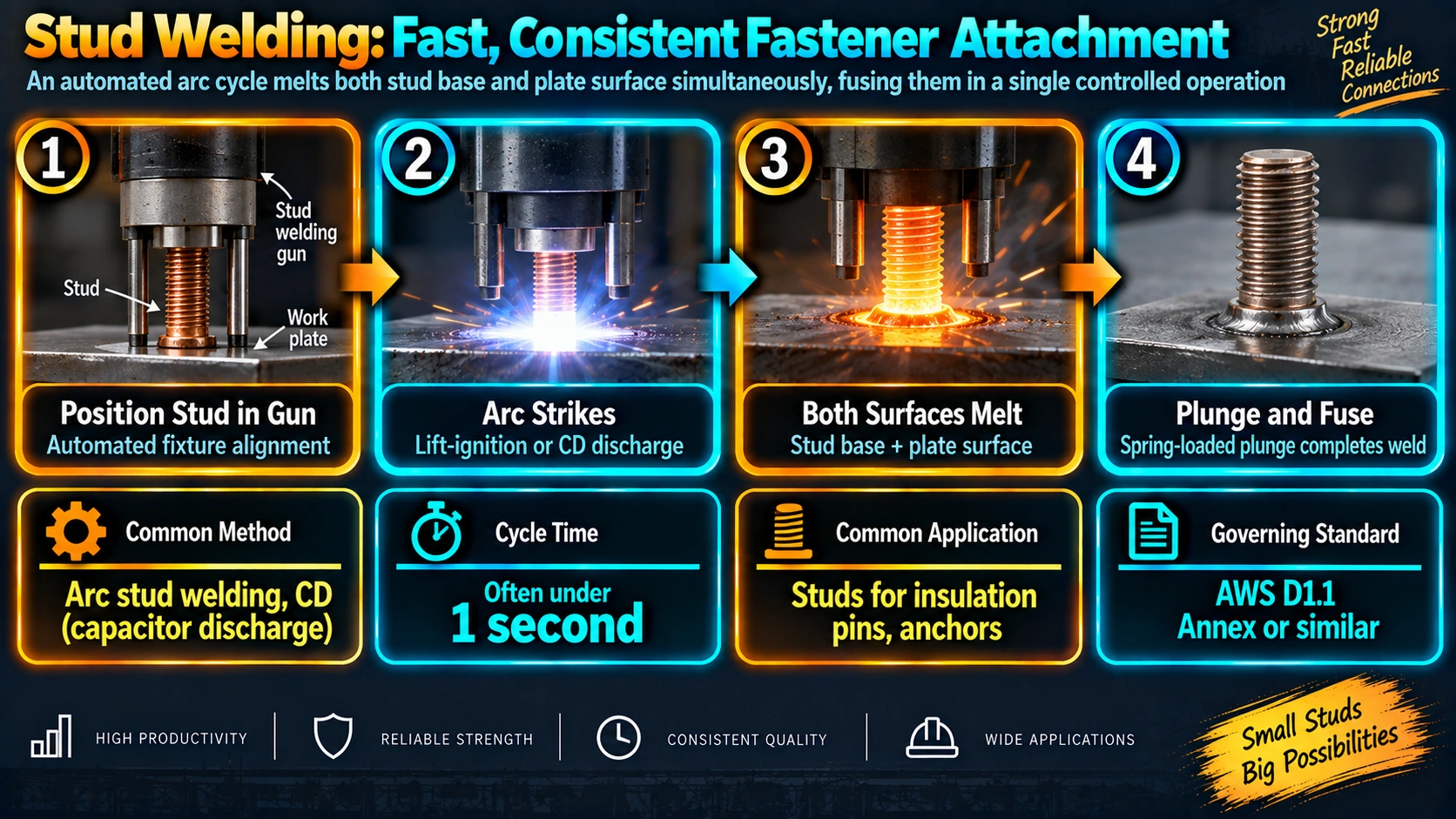
A stud welding gun holds the stud against the base plate, then lifts it a small controlled distance to draw an arc between the stud tip and the plate surface. The arc melts a thin layer of both the stud tip and the base plate almost instantaneously. Once the weld timer or capacitor discharge completes, the gun’s spring or pneumatic mechanism plunges the stud back down into the molten pool, and the two molten surfaces forge together as they solidify, producing a full-penetration, full-strength joint around the entire cross section of the stud in a single operation that typically takes well under one second.
Weld current and time
Weld current for drawn arc stud welding is typically supplied by a DC constant-current power source similar in principle to those used for SMAW, but the arc time is controlled automatically by the stud gun’s timer rather than by an operator, which is what makes the process so repeatable.
Drawn Arc vs Capacitor Discharge Stud Welding
Drawn arc (DA) stud welding
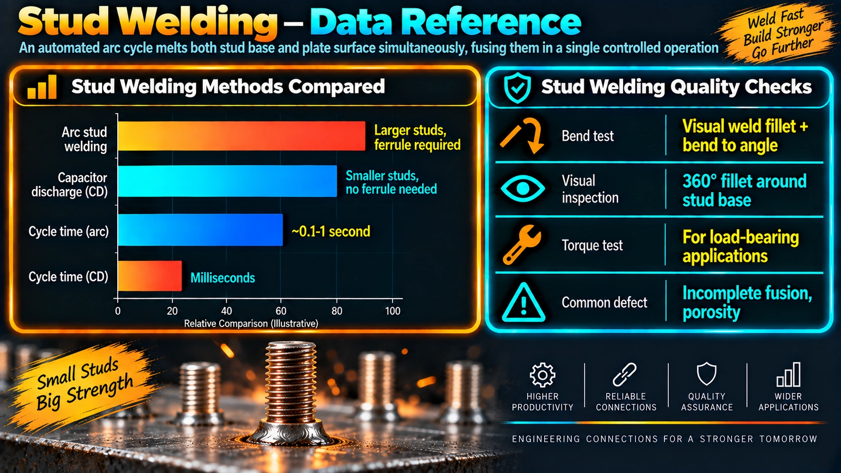
Drawn arc welding sustains an arc for a set weld time, typically in the range of tens to a few hundred milliseconds, and is used for stud diameters from roughly 3 mm up to 25 mm or larger. It normally requires a ceramic ferrule to shield the arc and contain the flash, and it produces a distinctive raised fillet of solidified flash completely around the base of the stud.
Capacitor discharge (CD) stud welding
Capacitor discharge welding stores energy in a capacitor bank and releases it in an extremely short, intense discharge, typically only a few milliseconds. This very short weld time deposits far less total heat into the base plate, which is why CD stud welding is the preferred method for thin sheet metal, stainless steel, and applications where minimal or no visible mark on the reverse side of the plate is required. CD studs typically use a small tip or flange feature rather than a ferrule to initiate and control the arc.
| Characteristic | Drawn Arc (DA) | Capacitor Discharge (CD) |
|---|---|---|
| Typical weld time | Tens to hundreds of ms | A few ms |
| Stud diameter range | 3 mm to 25 mm+ | Typically up to about 10 mm |
| Minimum base thickness | Moderate to thick | Down to about 0.5 mm |
| Ferrule required | Yes (typically) | No (or small tip feature) |
| Reverse-side marking | Visible discoloration possible | Minimal to none |
| Typical applications | Shear connectors, structural anchors | Sheet metal, enclosures, stainless trim |
Key Stud Welding Process Parameters
Weld current
Sets the arc energy for drawn arc welding; higher current is needed for larger stud diameters and thicker base material to achieve full fusion around the stud’s entire cross section.
Weld time
Controls the duration the arc is sustained before plunge. Insufficient weld time leaves incomplete fusion at the joint; excessive weld time increases distortion and can burn through thin base material.
Lift height
The small gap the gun creates between the stud tip and the plate to initiate and sustain the arc. Lift height must match the stud diameter and weld current for a stable arc.
Plunge force and speed
The spring or pneumatic force that drives the stud into the molten pool after arc time completes. Adequate plunge force is essential to forge the two molten surfaces together and expel contaminants into the flash fillet rather than trapping them in the joint.
Common Stud Welding Defects
Incomplete flash fillet
A gap or thin section in the 360-degree flash ring around the stud base usually indicates insufficient current, contaminated or coated base metal at the weld location, or a stud that was not held perpendicular to the plate during welding.
Porosity in the weld zone
Porosity can result from moisture or mill scale on the base plate surface, or from a damaged or wet ceramic ferrule that fails to properly shield the molten pool during drawn arc welding.
Undercut and base plate burn-through
Excessive weld current or weld time relative to base plate thickness can cause undercut around the stud base or, on thin sheet, complete burn-through, which is one of the main reasons capacitor discharge welding is specified for thin material instead of drawn arc.
Applications of Stud Welding
Structural and composite construction
Headed shear connector studs welded to structural steel beams are a defining application, transferring shear load between the steel beam and a composite concrete deck in bridge and building construction.
Shipbuilding and heavy fabrication
Threaded studs for temporary fixturing, insulation pins, and cable tray supports are commonly stud welded directly to hull plating and structural steel because the process is fast enough to keep pace with fabrication schedules.
Sheet metal and enclosures
Capacitor discharge stud welding attaches standoffs, ground studs, and fastener bosses to thin steel and stainless enclosures, appliance panels, and automotive body panels without the distortion or reverse-side marking that drawn arc or resistance processes can leave.
Electrical and grounding
Grounding studs welded directly to structural steel or equipment housings provide a reliable, code-recognized electrical bond point without drilling and bolting.
Frequently Asked Questions
What is stud welding used for?
What is the difference between drawn arc and capacitor discharge stud welding?
What is a ferrule used for in stud welding?
How is stud weld quality checked?
Can stud welding be used on thin sheet metal?
What welding standard governs stud welding procedures?
Why does stud welding not need filler metal?
Recommended Reading
Welding Handbook (AWS), Volume on Welding Processes
Reference coverage of stud welding equipment, procedure variables, and quality control alongside other arc processes.
View on AmazonStructural Welding Code Study Guide (AWS D1.1)
Companion reference for engineers and inspectors working with AWS D1.1 stud welding and structural welding provisions.
View on AmazonWelding Inspection Handbook
Practical inspection methods including bend testing and visual acceptance criteria applicable to production stud welds.
View on AmazonSteel Construction Manual
Reference for composite deck design and shear connector specification relevant to structural stud welding applications.
View on AmazonDisclosure: WeldFabWorld participates in the Amazon Associates programme (StoreID: neha0fe8-21). If you purchase through these links, we may earn a small commission at no extra cost to you. This helps support free technical content on this site.