Tube to Tubesheet Welding Qualification — Complete Guide
Tube to tubesheet welding is one of the most specialised weld joint types encountered in pressure vessel fabrication. It is a critical joint in heat exchangers, condensers, and boilers — where the integrity of each individual tube-to-tubesheet weld directly determines whether the exchanger can maintain separation between two process fluid streams. A single leaking joint can contaminate product, cause unplanned shutdowns, or create a safety hazard in toxic or high-pressure service. This guide covers all aspects of the tube-to-tubesheet welder and welding operator qualification process as required by ASME BPVC Section IX.
What is Tube to Tubesheet Welding?
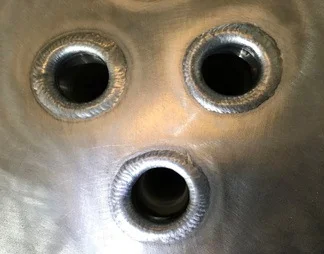
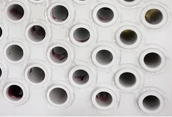
Tube to tubesheet welding is the process of attaching individual tubes to the tubesheet plate of a shell-and-tube heat exchanger, condenser, or similar pressure equipment. The tubesheet is a thick plate drilled with a regular array of holes — each hole receives one tube, and the tube is then welded at the face of the tubesheet to form a pressure-tight joint.
This joint type is fundamentally different from standard groove or fillet welds in several important respects. The access is severely restricted — the welder (or automated welding head) must work in the confined space between adjacent tube holes. The joint geometry is annular rather than linear. The wall thickness of the tube is typically very thin (often 1.2 mm to 3 mm), demanding extremely precise heat input control to achieve full fusion without burning through the tube wall. For these reasons, qualification of a welder or welding operator for groove welds alone does not qualify them for tube-to-tubesheet welding. A specific, separate qualification process is required.
The failure modes unique to tube-to-tubesheet joints include burn-through of the tube wall, lack of fusion at the tube-to-tubesheet interface, cracking in the heat-affected zone of the thin tube wall, and insufficient minimum leak path (MLP) — all of which can allow cross-contamination of the shell-side and tube-side fluids. Because the entire heat exchanger bundle must be replaced if systematic weld failure is discovered after fabrication, the qualification and production welding of these joints carries substantial financial and schedule risk in addition to the safety implications.
Key Terminology for Tube to Tubesheet Joints
ASME Section IX defines specific terminology for this joint type that must be understood before interpreting the qualification requirements. The following terms are fundamental:
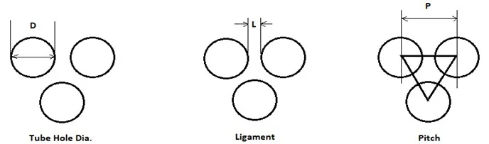
Tube Hole (D)
The through-hole drilled or bored in the tubesheet into which the tube is inserted. The tube hole diameter is slightly larger than the tube OD to allow insertion and, in some designs, tube expansion before welding.
Ligament (L)
The shortest distance between the edges of two adjacent tube holes in the tubesheet. The ligament dimension governs the structural integrity of the tubesheet and determines how closely tubes can be packed. A narrow ligament limits the fillet weld size that can be deposited without undercut into adjacent holes.
Pitch (P)
The centre-to-centre distance between adjacent tube holes, measured in the pitch direction (triangular or square layout). Pitch = Tube OD + Ligament (for a single-diameter tubesheet with no expansion grooves).
Minimum Leak Path (MLP)
The shortest path a fluid at the root of the weld would need to travel to escape from the joint to the atmosphere or the other side of the tubesheet. The MLP must meet or exceed the value required by the applicable construction code or engineering design.
Strength Weld
A tube-to-tubesheet weld intended to carry mechanical loads in addition to providing pressure tightness. The MLP for strength welds is the minimum distance a fluid must travel from the weld root to the nearest free surface — controlling the effective throat of the weld in the leak path direction.
Seal Weld
A tube-to-tubesheet weld whose primary function is pressure tightness only, not mechanical strength. Tubes in seal-welded tubesheets are typically expanded into the tubesheet before welding, so the expansion carries the mechanical load and the weld provides the seal.
Minimum Leak Path — Definition and Importance
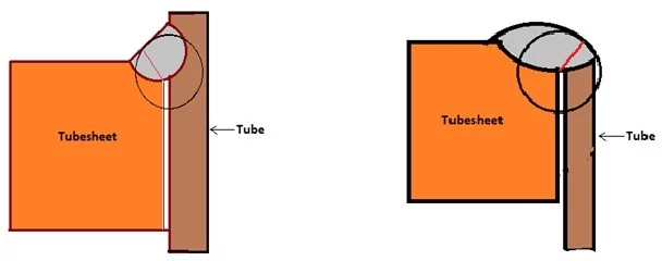
The Minimum Leak Path (MLP) is the critical design parameter that governs the size and depth of the tube-to-tubesheet weld. It is defined as the shortest distance from the root of the weld to the nearest free surface — that is, the shortest path a fluid under pressure at the weld root would need to travel to escape from the joint.
In a full-strength tube-to-tubesheet weld, the MLP is measured from the deepest point of weld penetration (the root) to either the tubesheet face or the tube bore — whichever is closer. The MLP must equal or exceed the value specified by the construction code (such as ASME Section VIII Div. 1 or Div. 2) or the engineering design document for the heat exchanger.
The MLP is verified during qualification through macro-section examination of the mockup welds (described in detail in the Testing Requirements section below). It cannot be confirmed by visual or liquid penetrant examination alone — only a properly prepared macro-section through the weld centre reveals the true root position and confirms that the MLP requirement has been met.
Why Groove Weld Qualification is Not Sufficient
One of the most important requirements in ASME Section IX for tube-to-tubesheet joints is stated plainly in QW-387: the integrity of this joint type cannot be assured by groove welding qualification alone. This is not a formality — it reflects genuine technical differences between the two joint types that make cross-qualification inappropriate:
- Joint geometry: Groove welds involve linear or curved joints with consistent access from one or both sides. Tube-to-tubesheet joints are annular joints welded in a confined circular pass around the tube circumference, with access severely restricted by the adjacent tubes and the tubesheet face.
- Tube wall thickness: Heat exchanger tubes are typically 1.2 mm to 3.0 mm thick — far thinner than the plates normally used in groove weld qualification coupons. Heat management to avoid burn-through at these thicknesses requires a fundamentally different technique.
- Proximity effects: In production, the tube being welded is surrounded by already-welded adjacent tubes. The heat input, arc characteristics, and shielding gas behaviour are affected by this proximity in ways that cannot be replicated in a groove weld coupon test.
- Orbital and automated welding: Many tube-to-tubesheet operations use automatic orbital welding heads. The qualification requirements for welding operators controlling automated equipment differ from manual welder qualification, and the specific variables for orbital tube-to-tubesheet welding are captured in Table QW-388 rather than in the standard groove weld essential variables.
- Failure mode: The primary failure mode — insufficient MLP leading to a through-leak path — is unique to this joint type and cannot be evaluated by groove weld test specimens.
Tube-to-Tubesheet Welder and Welding Operator Qualification
ASME Section IX QW-387 governs the qualification of welders and welding operators for tube-to-tubesheet joints. The requirements differ depending on which construction code governs the heat exchanger being built:
ASME Section VIII Division 1
ASME BPVC Section VIII Division 1 does not mandate the use of QW-193 mockup qualification for tube-to-tubesheet joints as a prescriptive requirement. The manufacturer has the option to choose between two qualification methods:
- Demonstration mockup qualification per QW-193.2 (the specific tube-to-tubesheet test procedure), or
- A standard groove weld qualification per QW-303.1
When the groove weld qualification route is chosen for Div. 1 work, the welder or welding operator who passes the required groove weld test is qualified for tube-to-tubesheet joint welding. However, the applicable position limits, diameter restrictions, and essential variables of QW-350 (for welders) or QW-360 (for welding operators) still apply in full.
ASME Section VIII Division 2
ASME BPVC Section VIII Division 2 is more prescriptive. Per paragraph 6.3.4 of that standard, QW-193 mockup qualification is mandatory for tube-to-tubesheet joints. Groove weld qualification alone is not accepted as a qualification route for Division 2 pressure vessels. This stricter requirement reflects Div. 2’s higher allowable stresses and more rigorous engineering analysis requirements, where the quality of individual joint qualification must be demonstrably higher than the Div. 1 minimum.
Mockup Assembly Requirements (QW-193.2)
When the mockup qualification route is used (whether required by Div. 2 or chosen for Div. 1), the mockup must satisfy the following requirements:
- The mockup assembly must essentially duplicate the tube-to-tubesheet weld joint design to be used in production. This means the same tube OD, same tubesheet material, same tube projection (if any), same hole preparation (countersink, groove, or plain), and the same tube pitch and layout pattern.
- The mockup must satisfy the essential variables of QW-350 (for welders) or QW-360 (for welding operators), as applicable, in addition to the tube-to-tubesheet-specific variables of Table QW-388.
- A minimum of five mockup tube-to-tubesheet welds is required to qualify each individual welder or welding operator. These five welds are made in the mockup, tested, and must all meet the acceptance criteria described below.
- PWHT (Post-Weld Heat Treatment) may be omitted from the mockup qualification test even if PWHT is required in production. The rationale is that PWHT does not affect the welder’s skill in producing the weld; it is a production process variable rather than a qualification variable for this purpose.
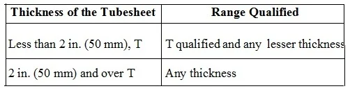
Tubesheet Thickness Qualification Range (QW-193.1)
The tubesheet used in the qualification mockup must be of sufficient thickness to be representative of production conditions. ASME Section IX QW-193.1 specifies the tubesheet thickness limits for welder qualification. These limits define the range of production tubesheet thicknesses for which the qualification is valid based on the thickness used in the mockup.
The qualification range principle is consistent with the broader ASME Section IX philosophy: the mockup must be representative of the production application, but a single qualification test qualifies the welder for a defined range of similar applications rather than requiring re-qualification for every incremental change in tubesheet thickness.
Essential Variables for Tube-to-Tubesheet Performance Qualification (QW-388)
In addition to the standard essential variables of QW-350 (for welders) and QW-360 (for welding operators), ASME Section IX Table QW-388 lists the specific essential variables that apply to tube-to-tubesheet welding. A change in any of these variables beyond the qualified limits requires re-qualification of the welder or welding operator.
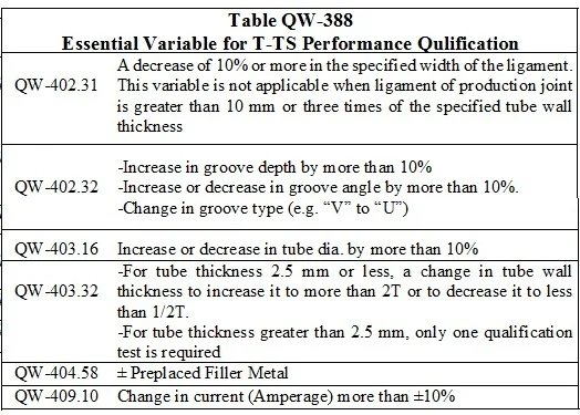
The key essential variables captured in QW-388 include, but are not limited to, the following categories:
| Essential Variable Category | Description | Effect of Change |
|---|---|---|
| Tube outside diameter | Change in OD of the tube being welded beyond the qualified range | Requires re-qualification — joint circumference and access geometry change |
| Tube wall thickness | Change in tube wall thickness beyond qualified range | Requires re-qualification — heat input management and burn-through risk change significantly |
| Tube hole type | Change from plain bore to countersunk, grooved, or other preparation | Requires re-qualification — joint geometry and weld access change |
| Tube projection | Change in the length by which the tube extends beyond the tubesheet face | Requires re-qualification — affects joint geometry and minimum leak path |
| Welding position | Position of the tube axis relative to the welder (horizontal, vertical, overhead) | Requires re-qualification — gravity affects the weld pool behaviour in the annular joint |
| Welding process | Change of welding process (e.g., GTAW to GMAW) | Requires re-qualification — arc characteristics and technique are fundamentally different |
| Automatic to manual (or reverse) | Change between automatic/mechanised orbital welding and manual welding | Requires re-qualification — operator skill and control method fundamentally differ |
| Base material P-number | Change in tubesheet or tube P-number beyond the qualified combination | Requires re-qualification — material weldability and thermal properties change |
Testing Required for Tube-to-Tubesheet Qualification Mockup
Once the qualification mockup has been welded, three examination methods are applied to the five test welds. All five welds must pass all applicable tests. The examinations and their acceptance criteria are as follows:
1. Visual Examination
All five mockup welds are first examined visually. The visual examination must confirm:
- Complete fusion is visible — the weld must show a continuous, uninterrupted bond around the full circumference of the tube
- The weld is free from cracks and from porosity visible to the naked eye
- There is no evidence of burning through the tube wall — burn-through results in a visible hole or collapse of the tube wall at or near the weld, and is an automatic rejection condition
2. Liquid Penetrant Examination
After visual examination, all five welds are examined by the liquid penetrant test method. The examination must be conducted in accordance with ASME Section V, Article 6. The acceptance criteria for liquid penetrant indications are:
- No relevant linear indications are acceptable — any indication whose length is more than three times its width constitutes a linear indication and is rejectable
- Rounded indications (those whose length is not more than three times their width) must not exceed 5 mm in any single dimension
- Groups of three or fewer rounded indications arranged in a line, separated by less than 1.5 mm, are acceptable provided each individual indication meets the 5 mm size limit
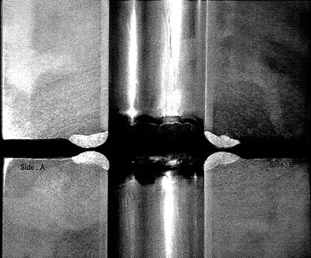
3. Macro-Section Examination
The macro examination is the definitive test for tube-to-tubesheet weld qualification. After visual and PT examinations are complete and accepted, each of the five mockup welds is sectioned through the centre of the tube to expose the weld cross-section. The sectioning exposes four faces per weld (two cuts through the tube centre at 90 degrees to each other gives four exposed faces per weld location, though the code specifies sectioning to give a minimum number of evaluable surfaces).
The four exposed surfaces are prepared for examination as follows:
- Ground smooth to produce a flat, even surface free from machining marks that would obscure the weld boundary
- Etched with an appropriate chemical etchant (such as nital for carbon steel) to reveal the weld metal, heat-affected zone (HAZ), and base metal boundaries
- Examined under magnification of 10X to 20X to evaluate the weld geometry and identify any discontinuities
The acceptance criteria for macro examination are:
- The weld must achieve the minimum leak path (MLP) dimension required by the design or construction code — this is verified by direct measurement on the macro section
- No cracking is acceptable in the weld metal, HAZ, or base metal visible at the examination magnification
- Complete fusion of the weld deposit into both the tubesheet face and the tube wall thickness must be demonstrated — the weld must show a continuous bonded interface at all locations
Qualification Process Overview
Production Welding Considerations for Tube-to-Tubesheet Joints
Qualification is only the starting point. Maintaining consistent weld quality in production — where hundreds or thousands of individual tube-to-tubesheet joints must be made — requires disciplined process control throughout fabrication.
Tube Preparation and Fit-Up
The tube must be cleaned of all contaminants — oil, oxide, drawing compound, and any protective coatings — for a minimum of 50 mm from the end before insertion into the tubesheet. Any contaminant at the joint interface can cause porosity, cracking, or lack of fusion in the completed weld. For stainless steel and nickel alloy tubes, oxide removal by grinding or chemical cleaning immediately before welding is standard practice.
The tube projection (the length by which the tube extends beyond the tubesheet face) must be controlled within the limits specified by the applicable WPS and confirmed by the qualification mockup. Excessive projection makes torch access difficult and can cause inconsistent weld geometry; insufficient projection reduces the available MLP.
Welding Sequence
In large tubesheets with hundreds of tubes, the welding sequence must be planned to minimise distortion and residual stress buildup in the tubesheet. Random or sequential row-by-row welding tends to cause progressive distortion. A balanced, back-step or symmetrical sequence — welding from the centre outward, or alternating between opposing quadrants — distributes heat more evenly and reduces cumulative distortion.
Interpass Temperature Control
Although tube-to-tubesheet welds are typically single-pass joints (the tube wall thickness is rarely sufficient for more than one pass), the interpass temperature of the tubesheet as a whole must be monitored when many joints are welded in close succession. Excessive cumulative heat input into the tubesheet can raise the temperature above the maximum interpass limit of the tubesheet material, potentially affecting its mechanical properties and causing distortion.
Inspection During Production
Per most quality plans and ASME construction code requirements, the production tube-to-tubesheet welds are subject to the same visual and liquid penetrant examination criteria as the qualification mockup. Many specifications additionally require periodic cross-section checks (one tube per tubesheet, or one per shift) to verify that the production MLP continues to meet the design requirement throughout the production run.
Summary — Qualification Method Comparison
| Requirement | ASME Sec. VIII Div. 1 | ASME Sec. VIII Div. 2 |
|---|---|---|
| QW-193 Mockup Required? | Optional (manufacturer’s choice) | Mandatory (para. 6.3.4) |
| Alternative to mockup? | Yes — groove weld per QW-303.1 | No — QW-193 is the only route |
| Minimum mockup welds | 5 welds per welder/operator | 5 welds per welder/operator |
| PWHT required on mockup? | May be omitted | May be omitted |
| Essential variables ref. | QW-350 / QW-360 + QW-388 | QW-350 / QW-360 + QW-388 |
| Visual Examination | Required — all 5 welds | Required — all 5 welds |
| Liquid Penetrant Test | Required — per ASME V Art. 6 | Required — per ASME V Art. 6 |
| Macro Examination | Required — 10X to 20X | Required — 10X to 20X |
| MLP verification | Per design / code requirement | Per design / code requirement |