Welding Documentation & Record-Keeping: Weld Maps, Traveller Cards, JHA, and Complete Data Book Guide
Welding documentation is the formal paper and electronic trail that proves every weld on a fabricated structure or pressure equipment was made correctly — by a qualified welder, to an approved procedure, from traceable materials, and with verified inspection results. It is not administrative overhead: it is the mechanism by which codes like ASME Section IX, ISO 3834, and EN 1090 enforce fabrication quality. When documentation fails, welds fail audit — and failed audits halt production, trigger costly rework, and in the worst cases result in catastrophic in-service failures with legal and regulatory consequences. This guide covers every document type in the welding quality system: from the job hazard analysis (JHA) that opens a hot-work permit to the Manufacturer’s Data Record (MDR) that closes out a pressure vessel for lifetime service.
The Welding Documentation Hierarchy
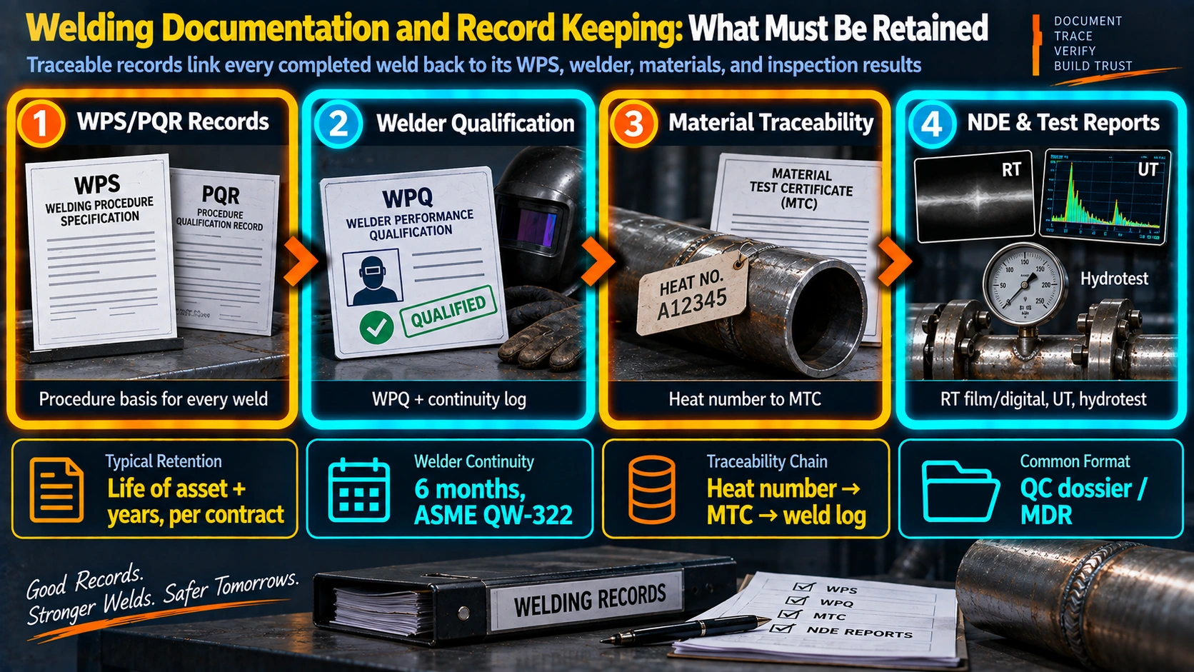
Welding documents sit in a three-tier hierarchy that mirrors the quality management system itself. Understanding how the tiers relate to each other is the foundation for building a compliant documentation system.
Tier 1 — Procedure Documents
Instruction and evidence documents that define and prove how welding must be done. Long-term retention; form the basis of every production weld authorisation.
Tier 2 — Personnel Qualification
Records proving each individual welder is qualified for the process, material, position, and thickness they are being asked to weld in production.
Tier 3 — Production Records
Documents generated during and after fabrication confirming that every individual weld in the product was made and inspected correctly.
Safety Documentation
Pre-task hazard analysis and permit-to-work documents that must be completed before any welding operation begins, especially in field, confined space, or hazardous area environments.
Material Traceability
Chain of custody documents linking every piece of base metal and filler material in the finished weld to the original manufacturer’s certifications and heat/lot numbers.
Final Closeout
The assembled record package submitted to the owner and regulatory authority at project completion, confirming all requirements of the applicable code have been met.
WPS, PQR, and WPQ — Procedure and Personnel Qualification Records
The three foundational procedure and personnel documents — WPS, PQR, and WPQ — are the most legally significant welding documents produced by any fabricator. They are the first documents requested by any competent inspector and the first to be challenged during an audit. A fabrication shop that cannot produce current, valid WPS and WPQ documents for every production weld cannot legally demonstrate code compliance.
Welding Procedure Specification (WPS)
A WPS is the welding instruction document. It tells the welder — and more importantly the inspector — exactly what parameters must be used for a specific weld. Under ASME Section IX, a WPS must address all the essential variables, supplementary essential variables (when notch-toughness testing is required), and non-essential variables applicable to the welding process used. The WPS is supported by a PQR; it references the PQR number on its face.
Procedure Qualification Record (PQR)
The PQR is the test record. It documents what actually happened during the welding of the qualification test coupon — the actual measured parameters (not the range from the WPS) — and the mechanical test results that prove the weld metal meets the minimum code properties. A PQR is generated once per qualification test; many WPS documents can reference the same PQR provided no essential variables are changed beyond the limits tested.
Welder Performance Qualification (WPQ)
A WPQ (also called a WPQR — Welder/Welding Operator Performance Qualification Record) documents that a specific named individual has demonstrated the skill to produce sound welds. Under ASME Section IX, a welder’s qualification is bounded by the process, P-Number group, F-Number, thickness range, diameter range (for pipe welds), and position used in the qualification test. Qualification expires after 6 months unless the welder maintains continuity of welding — meaning they have welded with that process at least once within any 6-month period, documented in the welder continuity log.
| Document | Who Creates It | Who Must Sign | Retention Period | Invalidated By |
|---|---|---|---|---|
| WPS | Welding Engineer | QC Manager; AI review | Permanent | Essential variable change; code edition change (if required) |
| PQR | Welding Engineer + Test Lab | Welding Engineer; Authorised Inspector | Permanent | Cannot be invalidated — only superseded by new test |
| WPQ | QC Inspector | QC Inspector; Welder signs acknowledgement | Minimum 6 years from last continuity entry | 6-month continuity lapse; process/material/position change beyond qualified range |
The Weld Map — Design, Content, and Use
The weld map is the master cross-reference document for a fabricated assembly. Every pressure vessel, piping spool, structural frame, or pressure equipment item produced to a code quality standard must have a weld map. It is typically a dimensioned isometric drawing (for piping spools) or orthographic fabrication drawing (for vessels and structural items) on which each weld joint has been assigned a unique sequential number.
What a Weld Map Must Show
A properly constructed weld map contains, as a minimum, the following information for every weld joint marked on the drawing:
- Unique Weld Number: A non-repeating identifier (e.g., SP-023-W01, SP-023-W02) that is the primary key linking the weld map to all other records
- WPS Reference: The WPS number and revision governing that joint
- Welder/Operator ID: The identity stamp number or name of the welder(s) who welded that joint
- NDE Method Required: RT, UT, MT, PT, VT — as required by code and specification
- NDE Report Reference: The report number and result (accept/reject/repair)
- PWHT Status: Whether PWHT is required and the PWHT chart reference number
- Joint Type and Dimension: Joint category (A, B, C, D per ASME VIII), thickness, diameter
- Acceptance Status: Final accept or reject status after all inspections
| Weld No. | Joint Type | WPS Ref. | Welder ID | NDE Method | NDE Report No. | PWHT Ref. | Status |
|---|---|---|---|---|---|---|---|
| SP-023-W01 | Butt / Cat. A | WPS-001 R02 | WLD-034 | RT + VT | RT-2024-0423 | N/R | ACCEPT |
| SP-023-W02 | Nozzle / Cat. D | WPS-003 R01 | WLD-021 | MT + VT | MT-2024-0117 | N/R | ACCEPT |
| SP-023-W03 | Butt / Cat. A | WPS-001 R02 | WLD-034 | RT + VT | RT-2024-0424 | N/R | REPAIR |
| SP-023-W03 (R) | Butt / Cat. A — Repair | WPS-001 R02 | WLD-041 | RT + VT | RT-2024-0502 | N/R | ACCEPT |
| SP-023-W04 | Butt / Cat. B | WPS-007 R00 | WLD-051 | UT + VT | UT-2024-0088 | PWHT-2024-031 | ACCEPT |
Weld Map Revision Control
The weld map is a controlled document. Any revision — adding a weld, changing a WPS reference, updating an NDE result, recording a repair — must follow the document control procedure: a new revision number is issued, the change is described in the revision block, and the previous revision is superseded (not deleted). All revisions must be retained in the document archive because the revision history is itself a quality record demonstrating the as-built condition evolved in a controlled manner.
The Weld Traveller Card — Shop-Floor Traceability
While the weld map is typically managed in the engineering office or QC department, the weld traveller card (sometimes called a weld traveller, work traveller, route card, or fabrication card) lives on the shop floor. It physically accompanies the component or spool from the first operation (material receiving and marking) through every subsequent stage until the item is released for despatch. The traveller is the real-time record of what happened, when, and who authorised each step. No step in the fabrication sequence may begin until the preceding step has been signed off on the traveller.
Structure and Mandatory Fields
| Step | Operation | Hold / Witness | Acceptance Criteria | Performed By / Sign | Date | QC Sign-off |
|---|---|---|---|---|---|---|
| 1 | Material Receiving & PMI | W | MTR verified; Heat No. marked on pipe | Stores / _________ | ________ | _________ |
| 2 | Cutting & Edge Prep | — | Bevel angle 37.5° ±2.5°; root face 1.5±0.5 mm | Fitter / _________ | ________ | _________ |
| 3 | Fit-Up Inspection (W01) | H | Root gap 2–4 mm; hi-lo ≤1.5 mm; tack welds to WPS-001 | QC Insp. / _________ | ________ | _________ |
| 4 | Preheat Verification | W | Min 10°C (or 80°C if ambient <5°C) | Welder / _________ | ________ | _________ |
| 5 | Root Pass — GTAW (W01) | W | WPS-001 R02 complied; Welder ID: WLD-034 | WLD-034 / _________ | ________ | _________ |
| 6 | Visual Inspection — Root | H | ASME VIII UW-35 / AWS D1.1 Cl.6 | QC Insp. / _________ | ________ | _________ |
| 7 | Fill & Cap Passes — SMAW (W01) | — | Interpass temp ≤250°C; E7018-H4 baked | WLD-034 / _________ | ________ | _________ |
| 8 | Visual Inspection — Final | H | Weld profile, reinforcement, undercut criteria | QC Insp. / _________ | ________ | _________ |
| 9 | Radiographic Testing (W01) | H | ASME VIII UW-51; 100% RT; accept per UW-51(b) | RT Level II / _________ | ________ | _________ |
| 10 | Dimensional Inspection | W | Per isometric drawing ±3 mm overall | QC Insp. / _________ | ________ | _________ |
| 11 | PMI (If specified) | W | Alloy composition verified against spec | PMI Tech. / _________ | ________ | _________ |
| 12 | Final Release / Despatch | H | All steps signed; weld map updated; data pack compiled | QC Manager / _________ | ________ | _________ |
Job Hazard Analysis (JHA) for Welding Operations
A Job Hazard Analysis — also called a Job Safety Analysis (JSA), Safe Work Method Statement (SWMS), or Task Risk Assessment (TRA) — is the document that systematically breaks a welding task into discrete steps, identifies every hazard at each step, assesses the risk level (typically using a Likelihood × Consequence matrix), and specifies the controls that reduce that risk to an acceptable level before work begins. In most jurisdictions, completing and communicating the JHA to all performing personnel is a legal requirement under occupational health and safety regulations, not just an industry best practice.
When a JHA Is Required for Welding
A JHA is mandatory before commencing any of the following welding-related activities:
- Any hot work (welding, grinding, cutting, brazing) in an operating plant or within a hot-work controlled area
- Welding in confined spaces (vessels, tanks, pits, trenches with restricted egress)
- Overhead or elevated welding (fall risk to welder and personnel below)
- Welding on pressure-containing equipment in or near service (live plant modifications)
- Welding of exotic materials generating hazardous fumes (stainless steels: hexavalent chromium; galvanised steel: zinc oxide; lead-painted surfaces)
- Field welding at non-routine locations where standard workshop controls may not apply
JHA Structure and Required Content
| Step No. | Task Step | Hazard Identified | Risk (L×C) | Controls Required | Residual Risk |
|---|---|---|---|---|---|
| 1 | Equipment setup; cable routing | Electric shock; trip hazard from cables | Medium | Inspect cables before use; route cables overhead or in cable guards; earth clamp secured to workpiece | Low |
| 2 | Grinding / edge preparation | Abrasive disc failure; flying debris; noise; vibration | Medium | Inspect disc before fitting; guard in place; face shield + hearing protection; vibration limit 2 hrs/day | Low |
| 3 | Preheat application (propane torch) | Fire; burns; LPG leak; explosion | High | Hot-work permit active; fire watch assigned; flashback arrestors fitted; gas cylinder secured upright; fire extinguisher within 5 m | Medium |
| 4 | Arc welding — all passes | UV/IR arc radiation; fume inhalation; electric shock; fire; burns; hot metal contact | High | Welding screen erected; LEV (local exhaust ventilation) active within 300 mm of arc; PPE: welding helmet (shade 10+), leather gloves, welding jacket, safety boots; RA for fume type (check SDS for consumable) | Medium |
| 5 | Slag removal / inter-pass cleaning | Hot slag; flying chips; eye injury | Medium | Allow interpass cool-down; face shield; chip hammer with guard | Low |
| 6 | Post-weld inspection; component handling | Crush injury from rotating/moving component; hot metal contact | Medium | Positioner lockout before entering work zone; verify component cool (<50°C) before MT/VT inspection; rigger supervises any lift | Low |
JHA and the Hot-Work Permit System
The JHA is a prerequisite for obtaining a Hot-Work Permit (HWP) in any plant or construction environment. The HWP is a separate, time-limited permit (typically valid for a shift — 8 to 12 hours) that authorises the specific hot-work activity at the specific location on the specific date. The permit requires sign-off from the area authority (area operations supervisor or permit issuer), the fire watch attendant, and the performing supervisor. It is not sufficient for the welding JHA to be complete — the HWP must also be issued, displayed at the work site, and closed out at the end of the shift with the fire watch confirming the area is clear. The JHA remains valid for the duration of the task (or until conditions change), while HWPs are renewed each shift.
NDT Documentation — Reports, Films, and Data Storage
Non-destructive testing generates its own complete set of documents that must be controlled and retained with the weld data book. The requirements for NDE documentation are specified in the applicable code (ASME VIII, ASME V, EN 13068, EN 1435) and the employer’s written practice for NDE (required by ASME Section V and SNT-TC-1A).
Mandatory Content of an NDE Report
| Field | RT Report | UT Report | MT / PT Report |
|---|---|---|---|
| Report number & revision | Required | Required | Required |
| Date of examination | Required | Required | Required |
| Weld number(s) examined | Required | Required | Required |
| Applicable procedure / technique sheet no. | Required | Required | Required |
| Equipment make, model, serial number | X-ray unit or gamma source (Ir-192 / Se-75 / Co-60) | Flaw detector make / model; probe type, angle, frequency | Yoke / Prod type; current (MT); UV/visible (PT) |
| Film type / IQI type and sensitivity | Required (ASME V Art. 2) | N/A | N/A |
| Material type, thickness, diameter | Required | Required | Required |
| Coverage map (areas examined) | Film ID sketch | Scan area diagram | Area sketch |
| Defect record (location, size, type) | Required if found | Required if found | Required if found |
| Acceptance standard referenced | ASME VIII UW-51 / UW-52 | ASME VIII App. 12 | ASME V Art. 7/6 |
| Result: Accept / Reject / Conditional | Required | Required | Required |
| NDE technician name, cert level, cert no., signature | Required | Required | Required |
| Level III review (if required by spec) | Optional / as specified | Optional / as specified | Optional / as specified |
PWHT Documentation — Time-Temperature Records
Post Weld Heat Treatment generates one of the most legally significant documents in the fabrication record: the PWHT time-temperature chart. This is a continuous recording from calibrated thermocouples that provides incontrovertible evidence that the soak temperature, hold time, heating rate, and cooling rate specified in the code and PWHT procedure were achieved. Without an acceptable PWHT chart, the treatment cannot be considered complete and the vessel cannot be accepted.
Mandatory Elements of a PWHT Record
Material Traceability Documentation
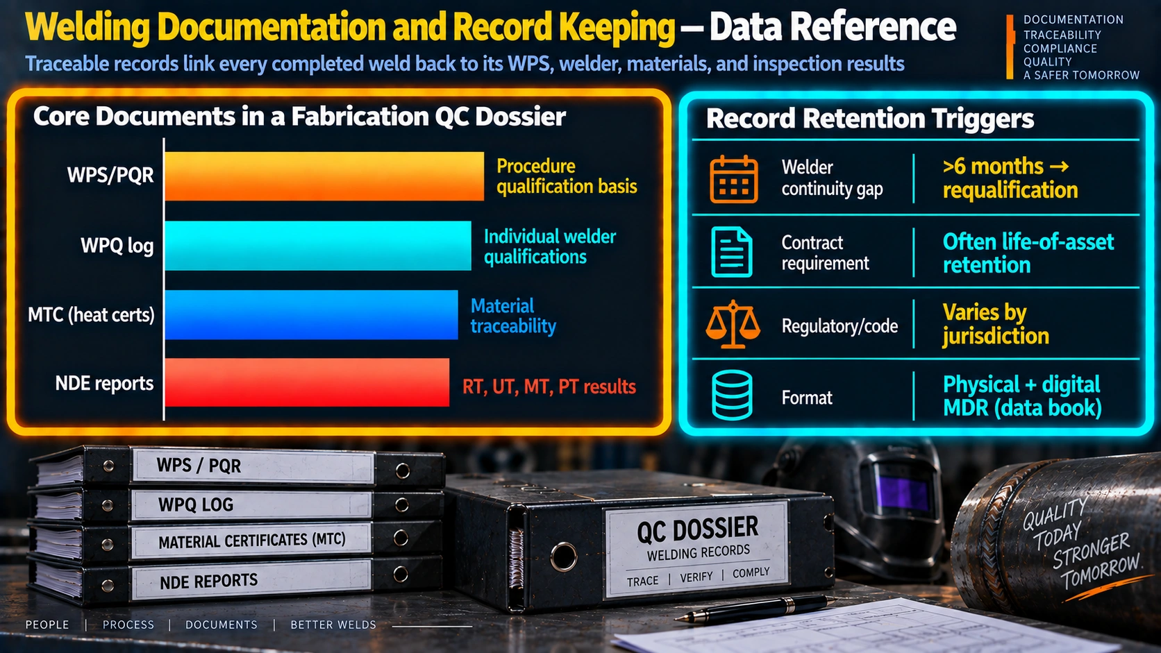
Material traceability is the ability to link every piece of pressure-containing material in the finished product back to the original mill certificate (Material Test Report, MTR) for that heat. This is not optional: ASME Section VIII UG-93 mandates material identification and certification for all pressure parts, and the requirement for traceability extends through every cutting, forming, and welding operation to ensure no uncertified material enters the pressure boundary.
The Material Traceability Chain
| Document | What It Certifies | Code Reference | Who Issues It |
|---|---|---|---|
| Mill Test Report (MTR) | Chemical composition, mechanical properties, heat treatment, heat number, product form dimensions | ASME SA-20 (plates); SA-530 (pipes); per ASTM standard for product | Steel mill / material manufacturer |
| PMI Report | In-situ chemical composition verification by XRF or OES, confirming material is as specified | Project spec / API RP 578 | PMI technician (site or third party) |
| Consumable Certificate | Chemistry and mechanical properties of weld filler metal (electrodes, wire, flux) by heat/lot number | AWS A5.x classification standards | Consumable manufacturer |
| Consumable Storage Record | Documented receipt, storage conditions (controlled humidity for low-hydrogen electrodes), baking records (temp, time, quantity), and issue log | ASME IX QW-408; manufacturer SDS | Stores / QC Dept. |
| Heat Number Transfer Log | Records that the heat number has been correctly transferred from parent material to each cut or machined piece | ISO 3834-2 §14; ASME VIII UG-93 | Fabrication / QC Dept. |
The Final Data Book / Manufacturer’s Data Record (MDR)
The data book — called a Manufacturer’s Data Record (MDR), Quality Record Package (QRP), or Final Documentation Package depending on the contract — is the assembled, bound collection of all quality records for a specific item of equipment. It is submitted to the owner on completion of fabrication and is retained for the design life of the equipment. For pressure vessels, it also contains the code data report (ASME Form U-1A or equivalent) that forms the legal basis for the equipment’s registration and operation.
Standard Data Book Section Index
| Section | Document Type | Typical Contents |
|---|---|---|
| 01 | Project & Equipment Index | Data book index, equipment tag, data sheet, design conditions, applicable code and edition |
| 02 | Approved Drawings | Fabrication drawings (as-built), vessel isometrics, nozzle orientations, support details — all stamped Approved for Construction (AFC) |
| 03 | Material Certifications | MTRs for all pressure parts; consumable certificates; PMI reports; heat number transfer log; shelf materials list |
| 04 | WPS / PQR Documents | Copies of all WPS and PQR documents referenced on the weld map; certificate of essential variable compliance |
| 05 | Welder Qualification Records | WPQ/WPQR for every welder who worked on the item; continuity log extract showing current qualification status at time of welding |
| 06 | Weld Map & Weld Joint Index | Complete weld map drawing; weld joint index table listing every weld with WPS, welder, NDE, PWHT, and status references |
| 07 | Production Weld Log | Chronological log of all welds made: date, welder, joint ID, process, consumable lot, preheat, result |
| 08 | Fit-Up & Visual Inspection Records | Fit-up inspection reports for all joint categories; visual inspection records for all welds — QC inspector signed |
| 09 | NDE Reports | All RT, UT, MT, PT reports with film/data storage location; repair records and re-examination reports; NDE personnel cert copies |
| 10 | PWHT Records | PWHT procedure; time-temperature strip charts with thermocouple layout sketches; calibration certificate for recorder and TCs |
| 11 | Dimensional Inspection | As-built dimensional reports for shell, heads, nozzles, supports; tolerance acceptance confirmation |
| 12 | Hydrotest Record | Test pressure calculated value; test gauge calibration certificate; test duration; inspector sign-off; leak/distortion finding (if any) |
| 13 | Coating / Painting Records | Surface prep inspection (cleanliness, profile); DFT measurements; coating system data sheets; holiday test report |
| 14 | NCR / CAR Register | Non-conformance reports raised during fabrication; corrective action records; disposition (use-as-is, repair, rework, reject); closure sign-off |
| 15 | Code Data Report & Nameplate | ASME Form U-1A (or equivalent EN / PED declaration); Authorised Inspector countersignature; nameplate rubbing or photograph |
Document Retention Requirements
| Document Type | ASME Section IX | ISO 3834-2 | Typical Owner Requirement |
|---|---|---|---|
| WPS | Permanent (as long as fabricator holds ASME cert.) | Permanent | Permanent |
| PQR | Permanent | Permanent | Permanent |
| WPQ / WPQR | Minimum 6 years (QW-322); renewed by continuity | During qualification validity + 2 years | 6–10 years from project completion |
| Production Weld Records / Traveller | Code does not specify; MDR requirement by contract | Until responsibility ceases; min 5 years | Design life of equipment (20–40 years) |
| NDE Reports & Films | Code does not specify; ASME V recommends 7 years for RT film | Until responsibility ceases; min 5 years | Design life; digital archiving recommended |
| PWHT Charts | Part of MDR; retained with vessel records | Until responsibility ceases | Design life |
| MTRs | Part of MDR; retained with vessel records | Permanent | Permanent |
| JHA / Safety Records | Not specified by welding code; per HSE regulations | Not specified | Typically 7 years per HSE regulations |
Common Documentation Non-Conformances and How to Prevent Them
The following table summarises the most frequently cited welding documentation non-conformances found during ASME, ISO 3834, and owner audits — and the corrective actions that prevent recurrence.
| NCR Category | Specific Finding | Root Cause | Preventive Action |
|---|---|---|---|
| WPS/PQR | Production weld uses an essential variable (e.g., F-Number) outside the range covered by the referenced PQR | Incorrect WPS selected; welding engineer not consulted when consumable changed | Pre-job WPS review checklist; QC engineer to confirm WPS applicability before welding commences |
| WPQ | Welder’s continuity lapse — has not welded with the qualified process in the preceding 6 months | No continuity log maintained; welder reassigned to different process | Monthly automated continuity log audit; renewal tests scheduled at 5-month mark |
| Weld Map | Weld map not updated after repair; NDE re-examination report not cross-referenced | QC staff did not close the repair loop on the weld map | Formal repair disposition procedure requiring weld map update as a sign-off step before re-examination |
| Traveller | Unsigned hold point — component has progressed to next stage without QC sign-off on preceding step | Production pressure; informal verbal approval not documented | Physical traveller card must travel with item; shop supervisor cannot move item without QC signature |
| NDE | NDE report missing film ID reference or coverage map | Non-standard report format; NDE technician not trained on form requirements | Pre-approved NDE report template with mandatory fields; Level III review of all reports before filing |
| PWHT | TC count insufficient; not all thermocouples reached minimum soak temperature | TC placed incorrectly; insulation blanket gap at TC location | Pre-PWHT TC layout drawing reviewed by QC; minimum soak temp. verified for all TCs by QC engineer before chart is accepted |
| MTR | Heat number on material does not match MTR submitted; possible material mix-up | Material re-marking during fabrication; multiple heats of same grade in shop | PMI verification at receiving; mandatory heat number check at each cut; colour-coding of materials by heat |
Recommended Reference Books on Welding Quality & Documentation
Frequently Asked Questions
What is a weld map and why is it required?
A weld map is a dimensioned isometric or orthographic drawing on which every weld joint in a fabricated item is uniquely numbered and cross-referenced to the applicable WPS, filler metal, welder ID, NDE method and results, and PWHT status. It provides a single traceability document linking physical weld locations to all supporting quality records. Weld maps are required by ASME Section IX, ISO 3834-2, and most EPC and owner specifications as a mandatory element of the Manufacturer’s Data Record (MDR) or weld data book. Without a complete weld map, it is impossible to verify that every weld in the assembly has been made to an approved procedure and inspected — making the fabrication non-code-compliant regardless of the actual weld quality.
What is a welding traveller card?
A weld traveller card (also called a route card, fabrication card, or weld record card) is a document that physically accompanies a spool, component, or assembly through the fabrication shop. It records in chronological sequence every production operation — fit-up inspection, preheat verification, welding, visual inspection, NDE, PWHT, dimensional check, and final release — with each step signed off by the responsible person before the item can proceed to the next stage. It serves as the shop-floor audit trail that feeds the weld map data and proves each mandatory hold point was properly inspected. Unsigned hold points on a traveller are a major non-conformance and can trigger production shutdown and retrospective inspection.
What is a JHA in welding and what should it contain?
A Job Hazard Analysis (JHA), also called a JSA or Task Risk Assessment, is a document that breaks a welding task into discrete steps, identifies every hazard at each step, assigns a risk level, and specifies the controls required to reduce each risk before work begins. For welding operations, the JHA must address: electric shock, UV/IR arc radiation, welding fume and gas hazards (including hexavalent chromium from stainless steels), fire and explosion from hot work, confined space risks, fall protection for elevated work, PPE requirements (welding helmet, leather gloves, welding jacket), and emergency response. The JHA must be task-specific, communicated to and signed by all performing crew before work starts, and retained as a safety record. It is a pre-requisite for the Hot-Work Permit in any controlled environment.
How long must welding records be retained?
Retention periods vary by code and jurisdiction. WPS and PQR records must be retained permanently as long as the fabricator holds its certification. WPQ records must be retained for a minimum of 6 years per ASME Section IX QW-322, with continuity entries required at least every 6 months to maintain qualification validity. Production weld records (traveller cards, weld maps, NDE reports, PWHT charts, hydrostatic test records) are typically required by owner specifications to be retained for the design life of the equipment plus 5 years, which for most pressure vessels means 25 to 40 years. JHA and safety records are retained per applicable HSE regulations, typically 7 years minimum. Digital EDMS storage is increasingly required to ensure long-term accessibility of these records.
What documents are included in a welding data book or MDR?
A Manufacturer’s Data Record (MDR) or weld data book for pressure equipment typically includes: the equipment data sheet and AFC drawings, material test reports (MTRs) for all pressure parts, qualified WPS and PQR documents, WPQ records for all production welders, the weld map with weld joint index, production weld log, fit-up and visual inspection records, all NDE reports with film/data location references, PWHT time-temperature charts with thermocouple layout sketches, dimensional inspection records, hydrostatic test record, coating inspection report, NCR and corrective action records, and the ASME Form U-1A or equivalent code data report with Authorised Inspector countersignature. The data book is submitted to the owner at project completion and retained for the design life of the equipment.
What is ISO 3834 and how does it relate to welding documentation?
ISO 3834 is the international standard specifying quality requirements for fusion welding of metallic materials. It has three compliance levels: ISO 3834-2 (comprehensive), ISO 3834-3 (standard), and ISO 3834-4 (elementary). The standard defines a complete documentation framework including WPS, PQR, welder qualifications, material records, production weld records, NDE records, dimensional inspection, PWHT records, and NCR records. Fabricators certified to ISO 3834-2 must demonstrate a functioning quality management system covering all these documents. Certification is increasingly required by European owners and EPC contractors as a pre-qualification condition for welding fabricators, and is a mandatory requirement under EN 1090-2 for structural steelwork with CE marking.
What is the difference between a WPS, PQR, and WPQ?
A WPS (Welding Procedure Specification) is the instruction document telling a welder exactly how to make a specific weld: process, material P-Number, filler F-Number, position, preheat, interpass temperature, and heat input range. A PQR (Procedure Qualification Record) is the test record proving the WPS produces welds with acceptable mechanical properties — it documents actual measured welding parameters during a test coupon and the mechanical test results (tensile, bend, impact, hardness). A WPQ (Welder Performance Qualification record) proves that a specific individual welder has the skill to produce sound welds using that process, material group, position, and thickness range. For a deeper dive, see the ASME Section IX quiz and reference guide.
What happens if welding records are lost or incomplete during an audit?
Missing or incomplete welding records during a code audit or owner inspection can result in rejection of fabricated items, production shutdown, mandatory re-inspection, and potential decertification of the fabricator’s ASME stamp or ISO 3834 certification. Vessels with missing weld records may need to be destructively tested, re-radiographed, or scrapped since there is no documented evidence that welds were made to an approved procedure by a qualified welder. Regulatory enforcement can result in financial penalties and reputational damage. This is why electronic document management systems (EDMS) and digital weld tracking systems are increasingly standard on large fabrication projects — the risk of paper record loss over a vessel’s 30-year operating life is significant.