SMAW Welding Technique: Common Mistakes vs Correct Technique — Complete Practical Guide
Shielded Metal Arc Welding (SMAW) — universally known as stick welding — is one of the oldest, most versatile, and most widely used welding processes in the world. From structural steelwork to pressure vessel fabrication, pipeline construction to maintenance welding, SMAW remains the first choice when portability, all-position capability, and tolerance to surface conditions matter most. Yet despite its apparent simplicity, SMAW demands genuine skill: the welder controls arc length, travel speed, electrode angle, and heat input entirely by hand and eye. The most common welding defects — porosity, lack of fusion, undercut, and irregular beads — are almost always traceable to one or more of four fundamental technique errors. This guide breaks down each error, explains the physics behind it, and gives you the correct technique to eliminate it from your welding.
Understanding the SMAW Process Before Correcting Technique
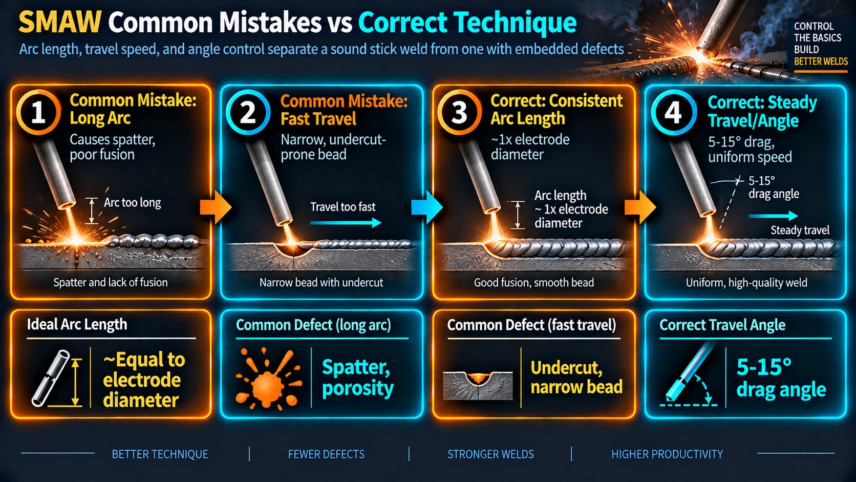
SMAW uses a consumable electrode consisting of a steel core wire coated with a flux compound. When the arc is struck between the electrode tip and the base metal, the intense heat (6,000–8,000°C at the arc column) melts both the electrode core and the base metal simultaneously, forming a weld pool. The flux coating decomposes in the heat to produce a shielding gas cloud that protects the molten pool from atmospheric oxygen and nitrogen, and forms a slag layer over the solidifying weld metal that provides additional shielding and controls the cooling rate.
Every technique variable the welder controls — arc length, electrode angle, travel speed, and amperage — directly affects the behaviour of this weld pool and the quality of the resulting weld. Understanding the physics of each variable is what separates a welder who can apply a remedy from one who only knows symptoms.
Arc Temperature
6,000 – 8,000°C
At the arc plasma; base metal melting point ~1,500°C. The arc converts electrical energy into heat energy that melts both electrode and base metal.
Typical Current Range
50 – 400 A
Varies by electrode diameter, position, and material. Lower range for thin material and overhead; upper range for flat heavy sections.
Electrode Consumption Rate
~25–35 cm/min
Typical burn-off rate for 3.2 mm E7018 at 120 A. The welder must feed the electrode at this rate while maintaining arc length — requiring simultaneous hand coordination.
Typical Weld Pool Width
8 – 18 mm
Depends on amperage, electrode diameter, and travel speed. Too wide = too slow; too narrow = too fast. Bead width should be approximately 2–3 electrode diameters for a flat bead.
Voltage (Arc Voltage)
20 – 40 V
Directly related to arc length — increasing arc length increases voltage. A welder maintaining correct arc length is therefore indirectly controlling the arc voltage.
Heat Input
HI = (V × A × 60) / (1000 × TS)
In kJ/mm, where TS is travel speed in mm/min. Controlled by the welder through travel speed and arc variables — key for metallurgical properties and HAZ control.
Mistake 1 vs Correct Technique — Arc Length
Of all the variables in SMAW, arc length is the most immediately consequential. It affects penetration, spatter, bead profile, atmospheric shielding, and weld metal chemistry simultaneously. The correct arc length is equal to approximately the diameter of the electrode core wire — roughly 2–4 mm for most standard electrodes.
What Goes Wrong
The arc is held too far from the base metal — more than one electrode diameter. The result is a characteristic set of interrelated defects that all stem from the same root cause: the arc plasma column becomes unstable and wide, spreading heat energy over a larger area rather than concentrating it.
- Excessive spatter: Arc becomes unstable, causing metal droplets to eject in all directions instead of transferring smoothly into the pool
- Weak, shallow penetration: Arc force is dispersed — insufficient directional energy to drive the pool into the root
- Wide, flat, irregular bead: Heat spread over a wider area produces a flat, wide bead with poor crown profile
- Porosity: Shielding gas cone is too wide and thin to adequately protect the pool — atmospheric nitrogen and oxygen dissolve in the molten metal and form pores on solidification
- High arc voltage: Longer arc = higher voltage, which changes the heat input balance
Correct Technique
Maintain arc length equal to the electrode diameter — approximately 2–4 mm. Keep the arc as short as possible without allowing the electrode coating to contact and contaminate the pool, and without stubbing (short-circuiting) the electrode into the base metal.
- Consistent sizzling sound: A correct SMAW arc has a steady, even crackling or frying sound — like bacon in a pan. Irregular or hissing sounds indicate arc length variation
- Smooth metal transfer: Short arc length forces directional droplet transfer into the pool with minimal spatter
- Good penetration: Concentrated arc force drives the pool deeper, especially important on root passes
- Consistent bead width: Stable arc = consistent heat input = uniform bead width and crown profile
Mistake 2 vs Correct Technique — Work Angle and Travel Angle
Electrode angle has two independent components that must both be controlled simultaneously: the work angle (orientation relative to the work surface / joint faces) and the travel angle (orientation in the direction of travel). Getting either wrong produces characteristic, recognisable defects.
What Goes Wrong
The electrode is leaned too far to one side (tilted away from the correct bisecting angle of the joint). This directs the arc force preferentially toward one side of the joint, causing:
- Poor fusion on the neglected side: The toe of the weld on the side away from the electrode has insufficient heat input to achieve fusion
- Unequal fillet leg lengths: On T-joints and fillet welds, one leg is longer and flatter than the other
- Undercut on the electrode side: Excess arc force on the leading face can erode the base metal without filling it back
- Irregular bead profile: The bead rolls toward the lower plate on inclined joints
Correct Technique
Work angle depends on the joint type and position. Always bisect the joint angle equally and adjust for gravity effects in positional welding:
- Butt weld, flat (1G): 90° to plate surface (vertical electrode)
- Fillet weld, flat (1F): 45° to both plate faces; directed into the root
- Horizontal fillet (2F): 30–45° to horizontal plate; tilt slightly toward vertical plate
- Travel angle: 10–15° push angle (electrode tip pointing forward in direction of travel) for better penetration and pool visibility
- Drag angle: 5–10° from vertical dragging back — used on vertical-down passes; reduces penetration
| Joint Type | Position | Work Angle | Travel Angle | Common Mistake |
|---|---|---|---|---|
| Butt joint | Flat (1G) | 90° to plate | 10–15° push | Tilting toward one side — uneven penetration |
| Butt joint | Vertical-up (3G) | 90° to plate | 0–5° push (nearly perpendicular) | Drag angle causing underrun and poor fusion |
| Fillet weld | Flat (1F) | 45° bisecting joint | 10–15° push | Electrode tilted toward one plate — unequal legs |
| Fillet weld | Horizontal (2F) | 30–45° to horizontal plate | 10–15° push | Too steep — pool runs down, convex bead |
| Fillet weld | Vertical-up (3F) | 45° to joint, triangular weave | Perpendicular to plate | Travel too fast — lack of fusion at toes |
| Butt joint | Overhead (4G) | 90° to plate | 5–10° push | Arc too long — weld falls out of joint |
Mistake 3 vs Correct Technique — Weld Bead Quality and Defects
The weld bead is the visual record of the welder’s technique. A smooth, uniform bead with consistent width, proper crown height, and clean fusion lines at both toes is the mark of controlled technique. An irregular bead — lumpy, wavy, with varying width and poor toe geometry — reveals parameter inconsistency. The image of an irregular bead in SMAW is not just aesthetic: each surface feature corresponds directly to a specific defect type that affects structural integrity and NDE outcome.
Causes of Irregular Beads
- Wrong travel speed: Varying the speed produces varying bead width and ripple spacing
- Inconsistent arc length: Changes arc energy and pool size continuously
- Wrong amperage: Too low creates a stiff, unresponsive pool that cannot smooth itself; too high creates a turbulent, fluid pool that flows uncontrollably
- Inconsistent electrode movement: Hand tremor, stopping, or varying weave width all show in the bead
- Dirty base metal: Oil, rust, moisture, or mill scale interrupts the arc and causes eruptions in the bead surface
Common defects produced: lack of fusion, porosity, undercut, overlap.
The Correct Bead Profile
A correctly made SMAW bead shows:
- Uniform width: Consistent throughout the run, approximately 2–3 times the electrode diameter
- Smooth, evenly spaced ripples: Each ripple represents one electrode feed cycle; consistent spacing = consistent travel speed
- Proper crown: Slight convexity above the base metal surface but within reinforcement limits
- Clean fusion toes: Weld metal blends smoothly into the base metal at both toes — no undercut groove, no cold-lap overlap
- Consistent colour: Uniform straw-to-grey slag colour — black scorched areas indicate arc instability or contamination
The Four Primary SMAW Bead Defects
Lack of Fusion (LOF)
Weld metal that has not fused with the base metal sidewall or the previous weld pass. Creates a planar, crack-like unbonded interface.
Causes: incorrect angle, travel too fast, current too low, arc too long, dirty joint surface.
Porosity
Gas pores trapped in the solidified weld metal — appear as rounded voids on RT film or as surface pits (surface-breaking porosity).
Causes: arc too long, damp electrodes, dirty base metal, insufficient preheat, current too high.
Undercut
Groove melted into the base metal at the weld toe that is not filled by weld metal. Reduces effective section and concentrates stress.
Causes: current too high, arc too long, wrong angle, travel speed too fast, electrode too large.
Overlap (Cold Lap)
Weld metal that has flowed over the base metal surface without achieving fusion — forms a notch at the weld toe similar to a crack.
Causes: travel too slow, current too low, excessive weave width, steep electrode angle.
Good Fusion
Complete metallurgical bonding between weld metal and base metal across the full joint interface. No voids or unbonded zones.
Achieved by: correct current, arc length, angle, travel speed, and clean base metal surface.
No Porosity
Dense, continuous weld metal with no gas inclusions. Radiograph shows solid weld without rounded voids.
Achieved by: short arc, dry baked low-hydrogen electrodes, clean base metal, correct current.
No Undercut
Weld toes blend smoothly into the base metal surface with no visible groove. Passes ASME UW-35(c) undercut limits.
Achieved by: correct current, 10–15° push angle, consistent travel speed, correct electrode size.
Proper Overlap Profile
Weld metal at toes fused cleanly — no cold lap, no rolled-over weld toe. Smooth transition from weld metal to base metal.
Achieved by: consistent travel speed, correct current, appropriate weave width, correct angle.
Mistake 4 vs Correct Technique — Travel Speed
Travel speed is the rate at which the welder moves the electrode along the joint axis. It is the primary variable controlling bead width, penetration depth, and heat input per unit length of weld. Unlike arc length and angle — which must both be right simultaneously — travel speed alone determines the cross-sectional geometry of the deposited bead and therefore directly controls whether the weld meets size requirements and passes visual inspection.
Too Fast — Narrow, Starved Bead
- Narrow bead with convex crown — insufficient metal deposited
- Poor, shallow penetration — arc moves past the joint before energy conducts into the root
- Undercut at weld toes — arc erodes the toe but the pool does not fill back fast enough
- Poor fusion at toe — insufficient time for the pool to wet the sidewalls
- Small ripple spacing = fast travel
Too Slow — Wide, Overloaded Bead
- Excessive weld metal buildup — bead wider and taller than required
- Overlap at weld toes — pool overflows the joint boundary without fusing
- Possible burn-through on thin material
- Excessive slag inclusion risk — pool is ahead of the arc, trapping slag under the weld metal
- Wide ripple spacing with wavy, irregular surface
Correct Technique
A steady, consistent travel speed produces all of the following simultaneously:
- Good penetration: Sufficient arc dwell time at each point to drive heat into the root
- Smooth, consistent bead width: Width remains approximately 2–3 electrode diameters throughout the run
- Minimal spatter: Arc is stable; pool is neither starved nor flooded
- Uniform ripple pattern: Evenly spaced ripples are the visual signature of consistent travel speed
- Correct reinforcement height: Bead crown within ASME UW-35(e) limits
Visual method: Watch the rear edge of the weld pool, not the arc. Maintain the pool at a fixed distance (6–10 mm) behind the arc at all times.
Correct Current Setting — The Foundation of All Four Parameters
All four technique parameters — arc length, angle, bead quality, and travel speed — are only fully controllable when the current (amperage) is set correctly for the electrode diameter, material thickness, and welding position. Incorrect amperage is the single root cause that makes good technique impossible even with perfect hand control, because it changes the fundamental behaviour of the arc and pool in ways the welder cannot compensate for.
| Amperage Condition | Arc Behaviour | Bead Appearance | Likely Defects | Fix |
|---|---|---|---|---|
| Too High | Violent, unstable arc; excessive spatter; large fluid pool hard to control | Wide, flat, irregular; heavy spatter around bead; possible burn-through on thin material | Undercut, porosity, burn-through, excessive reinforcement | Reduce amperage by 10–20 A; switch to smaller electrode if needed |
| Correct | Smooth, steady arc; consistent sizzle; pool fluid and controllable | Uniform width, smooth ripples, clean toes, correct crown height | None when combined with correct angle and travel speed | Maintain setting; check electrode OCV and cable connections if arc is erratic |
| Too Low | Weak arc; electrode stubs frequently; pool is stiff and sluggish | Narrow, convex, high crown; poor toe fusion; heavy slag difficult to clean | Lack of fusion (LOF), slag inclusions, incomplete penetration, overlap | Increase amperage by 10–20 A; check electrode condition and contact |
How to Avoid Common Welding Mistakes — Pre-Job Checklist
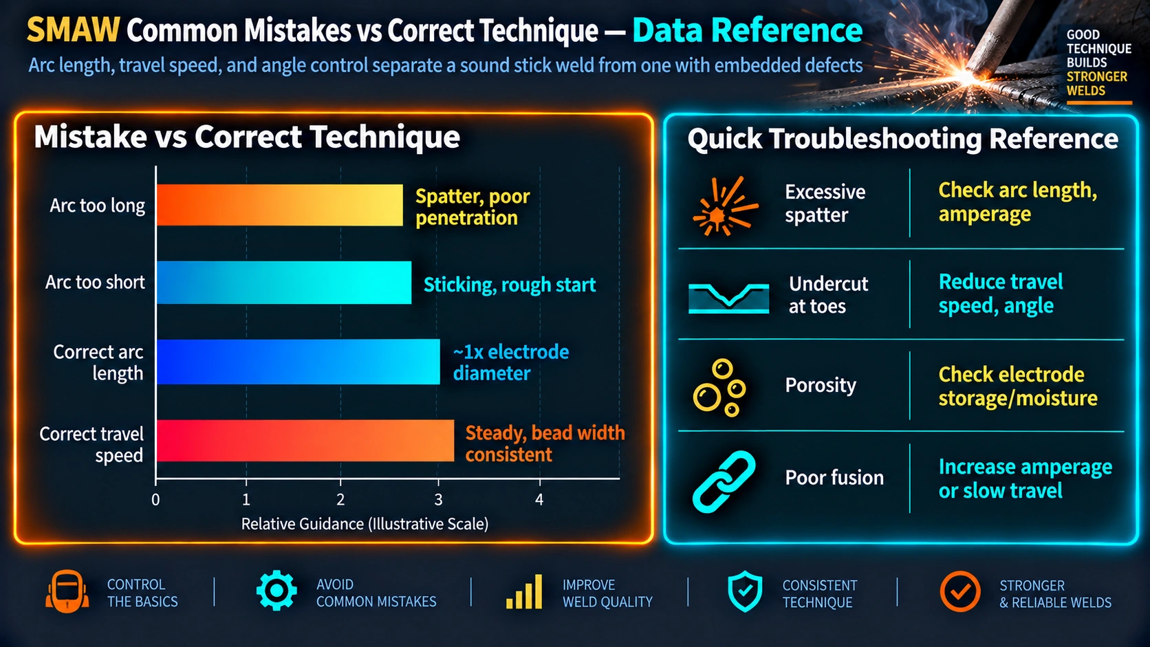
Professional welders and welding engineers know that most technique-related defects are preventable before the arc is struck. The five pre-job actions below address the root causes of the four common mistake categories discussed in this article.
1. Set Correct Current
Check the electrode manufacturer’s recommended range on the box or data sheet. Select amperage for the electrode diameter, position, and material thickness. Set the machine before striking the arc — not by trial and error during the run.
2. Choose the Right Electrode
Match the electrode classification to the base metal. E6013 for general mild steel; E7018-H4 for structural, P-No.1 pressure vessel welds, and any service requiring low hydrogen; specific alloy electrodes for Cr-Mo steels and stainless grades. Wrong electrode = wrong chemistry = wrong properties.
3. Clean the Base Metal
Remove all rust, mill scale, oil, paint, moisture, and surface contamination from the joint area and a minimum of 25 mm each side using angle grinder, wire brush, or solvent degreaser. Any contamination remaining becomes a source of porosity, LOF, or arc instability during welding.
4. Secure the Workpiece
Clamp, tack-weld, or fixture the joint to prevent movement during welding. Joint movement — even small amounts from heat distortion — changes the root gap and causes arc length variation. Proper fixturing prevents distortion defects and ensures dimensional compliance.
5. Practice Consistency
Steady hand, consistent arc length, consistent travel speed, and consistent electrode angle — these four variables must all be maintained simultaneously throughout the full length of each run. Practice running test beads on scrap plate using the correct parameters before welding the actual joint.
6. Bake Low-Hydrogen Electrodes
E7018, E7016, E8018, and other low-hydrogen classifications must be stored in a rod oven at 120–150°C and rebaked at 300–350°C/1 hr before use on critical joints. Moisture absorption causes hydrogen-induced cracking — invisible, delayed, and catastrophic in high-strength steels. See the consumable nomenclature guide for classification details.
Essential Equipment for SMAW Welding
Good technique cannot compensate for incorrect or poorly maintained equipment. The following items are required for safe, code-compliant SMAW welding.
| Equipment Item | Purpose | Key Selection / Maintenance Notes |
|---|---|---|
| SMAW Welding Machine | Provides constant-current (CC) output; maintains arc despite electrode movement | Must be rated for the electrode diameter and duty cycle required. DC output preferred for most applications (DC+: most electrodes; DC-: cellulosic root electrodes) |
| Electrode Holder (Stinger) | Clamps the electrode and transmits current from the welding cable to the electrode | Must be rated for the maximum amperage used; insulated jaws; clean jaw surfaces to ensure good electrical contact and prevent arc blow |
| Work/Ground Clamp | Completes the welding circuit by connecting the workpiece to the machine return | Place as close to the weld as possible; poor ground contact = arc instability and arc blow. Clean connection surface — do not ground through painted or rusted surfaces |
| Welding Electrodes | Consumable filler and flux source — burns in the arc to deposit weld metal and create protective slag | Match classification to base material and service; store low-hydrogen types in heated oven; check expiry of flux coating; do not use damaged or corroded electrodes |
| Welding Cables and Leads | Transmit current from machine to electrode holder and work clamp | Inspect before use for cuts, damage, or exposed conductor. Undersized cables cause voltage drop and reduce arc quality. Keep connections tight and clean |
| Chipping Hammer and Wire Brush | Remove slag from completed passes before the next pass or NDE | Chip while weld is still warm (but not too hot — wait 30–60 sec); chip at 45° angle along bead axis; full slag removal required before each pass to prevent slag inclusions |
Safety First — PPE and Hazard Controls for SMAW
SMAW welding exposes the welder and nearby workers to a specific set of physical, chemical, and electrical hazards. All must be controlled before work begins. The PPE and engineering controls below are non-negotiable — they are not optional depending on job type or duration.
SMAW Technique Troubleshooting Quick Reference
| Symptom Observed | Most Likely Cause(s) | Corrective Action | Defect Risk |
|---|---|---|---|
| Excessive spatter all around bead | Arc too long; current too high; damp electrode; wrong polarity | Shorten arc; reduce amps; bake electrode; check polarity (E7018 = DC+) | Porosity, surface contamination |
| Electrode sticks and shorts out | Arc too short; current too low; wrong polarity | Lengthen arc slightly; increase amps; check polarity | LOF, slag inclusions |
| Bead wanders left and right (arc blow) | DC magnetic arc blow; poor ground placement; heavily magnetised workpiece | Move ground clamp closer to weld; use AC current; place ground at both ends; reduce current | LOF, porosity, irregular bead |
| Slag difficult to remove — sticks to weld | Current too low; wrong electrode for base metal; weld cooled too fast | Increase amps; verify electrode classification; maintain recommended interpass temp | Slag inclusions if next pass run over unremoved slag |
| Surface pitting / surface porosity | Damp electrode; dirty base metal; arc too long; insufficient preheat on thick material | Bake electrodes; clean base metal; shorten arc; apply preheat per WPS | Subsurface porosity; potential LOF |
| Undercut at both weld toes | Current too high; travel speed too fast; arc too long; electrode too large for joint | Reduce amps; slow travel; shorten arc; use smaller electrode | Undercut — ASME UW-35(c) rejection if >1 mm or >10%t |
| Crack in weld bead (transverse or longitudinal) | Hydrogen-induced cracking (damp electrode, no preheat); hot cracking (high carbon or sulphur steel; crater crack) | Bake electrodes; verify preheat per carbon equivalent; fill craters before extinguishing arc; check base metal chemistry | Crack — mandatory rejection and repair |
| Burn-through (hole in base metal) | Current too high for material thickness; travel too slow; arc too short on thin material | Reduce amps; increase travel speed; use smaller electrode; fit backing strip | Open hole — must be repaired and re-examined |
Remember — The SMAW Quality Equation
Good Technique (arc length + work angle + travel speed) + Proper Settings (correct current + right electrode + baked low-hydrogen) + Patience (consistent practice + steady hand + clean base metal) = Strong, Clean, Defect-Free Welds
Recommended Books on SMAW and Welding Technique
Frequently Asked Questions — SMAW Welding Technique
What is the correct arc length for SMAW stick welding?
The correct arc length for SMAW welding is approximately equal to the diameter of the electrode core wire — typically 2 to 4 mm for standard electrodes. A practical rule of thumb: arc length equals electrode diameter (e.g., 3.2 mm electrode = approximately 3 mm arc length). Too long an arc causes excessive spatter, low penetration, wide flat beads, and porosity from atmospheric contamination. Too short causes stubbing and sticking. Develop arc length consistency by listening — a correct arc produces a steady, even crackling or sizzling sound. Arc length is directly related to arc voltage, so a correct arc length also means the welder is indirectly maintaining correct voltage.
What is the correct electrode work angle for SMAW?
For a flat butt weld (1G), the correct work angle is 90 degrees to the plate surface. For a flat fillet weld (1F), the electrode is held at 45 degrees bisecting the two joint faces and directed into the root. The travel angle (push angle) should be 10 to 15 degrees from vertical in the direction of travel for all positions. Using a push angle improves penetration and visibility of the pool. An incorrect work angle leads to poor fusion on one side, undercut on the high side, and unequal fillet leg lengths. For vertical and overhead positions the work angle follows the same principles but the travel angle is reduced to near-perpendicular to help control the pool against gravity.
What causes porosity in SMAW welding and how do you prevent it?
Porosity in SMAW is caused by gas entrapment in the solidifying weld pool. The main causes are excessive arc length (atmospheric contamination), damp or moisture-absorbed electrodes (hydrogen release), dirty base metal (rust, oil, paint, mill scale), insufficient preheat, and incorrect amperage. Prevention: maintain correct short arc length, bake low-hydrogen electrodes at 300–350°C for 1 hour before use, thoroughly clean the base metal, apply preheat per the applicable WPS, and verify the correct amperage setting before starting. For critical pressure vessel welds, electrode storage and baking records must be maintained as part of the quality documentation system.
What happens if travel speed is too fast or too slow in SMAW?
Travel speed that is too fast produces a narrow, convex bead with insufficient penetration, poor fusion at the weld toes, and undercut. Travel speed that is too slow produces an excessively wide, flat, or concave bead with overlap (cold lap) at the toes, possible burn-through on thin material, and trapped slag under the weld metal. The correct travel speed maintains the pool about 6 to 10 mm behind the arc and produces evenly spaced ripples of uniform width. Auditorily, correct travel speed combined with correct arc length produces a steady sizzling sound. Watch the rear edge of the weld pool — not the arc — to maintain consistent travel speed.
What is the difference between undercut and overlap in a weld bead?
Undercut is a groove melted into the base metal at the weld toe that is not filled by weld metal — it reduces the effective section and creates a stress concentration notch. It is caused by excessive current, too long an arc, or travel speed that is too fast. Overlap (cold lap) is the opposite — weld metal flows over the base metal surface without achieving fusion, forming a notch at the toe. It is caused by travel speed too slow, current too low, or excessive weave width. Both are surface-breaking defects visible by visual inspection and are rejectable under ASME UW-35(c), AWS D1.1, and most weld acceptance standards. Both require repair by grinding or additional weld deposition.
How do I choose the correct amperage for SMAW welding?
Always start with the electrode manufacturer’s recommended range. As a general rule, amperage is approximately 40 times the electrode diameter in mm — so a 3.2 mm E7018 electrode starts at around 120–130 A for flat position. Adjust down by 10–15% for vertical and overhead positions. Too high amperage causes excessive spatter, undercut, and burn-through; too low causes stubbing, poor fusion, and slag inclusions. The arc should produce a smooth, consistent crackling sound and a fluid pool that tracks smoothly behind the electrode. The MIG settings calculator on WeldFabWorld covers GMAW parameters; SMAW settings are always electrode-specific.
What PPE is required for SMAW welding?
Mandatory PPE for SMAW welding includes: a welding helmet with filter lens shade 10 (or shade 11–12 above 300 A) to protect against UV and IR arc radiation; leather welding gauntlets; a flame-resistant welding jacket or sleeves (leather or FR cotton); safety boots with steel toecap; and safety glasses under the helmet for slag chip protection. In confined spaces, or when welding stainless steel or coated materials, a powered air-purifying respirator (PAPR) or half-face respirator with P3 and ABEK filter is mandatory to protect against welding fume including hexavalent chromium. A fire extinguisher must be within 5 m of all hot-work and a fire watch must be maintained for at least 30 minutes after welding is complete.
Why do low-hydrogen electrodes like E7018 require baking before use?
Low-hydrogen electrodes such as E7018 have a flux coating specifically formulated to deposit weld metal with very low diffusible hydrogen (H4 suffix = max 4 mL/100g weld metal). If the coating absorbs atmospheric moisture, water decomposes in the arc to release hydrogen, which diffuses into the weld metal and HAZ, causing hydrogen-induced cracking (HIC) — delayed, invisible cracking that can occur hours or days after welding, especially in medium and high-strength steels. To prevent this, electrodes must be stored in a heated rod oven at 120–150°C and rebaked at 300–350°C for 1 hour before use on critical joints. Maximum time out of oven (exposure time) is 4 hours for E7018 per AWS A5.1. Baking records must be maintained as part of the welding quality records.