Crater Cracking in Welds — Causes and Prevention
Crater cracking is one of the most common yet most preventable defects a welder or welding engineer will encounter, and understanding it is essential to producing sound, code-compliant welds. It forms at the exact moment the arc is broken at the end of a weld bead, when the last pocket of molten metal — the crater — solidifies under conditions that almost guarantee cracking unless the welder actively compensates for them. Because the crater is the last region of the weld to freeze, it concentrates every unfavourable condition present in the joint: the highest level of shrinkage strain, the greatest segregation of low-melting impurities, and often the thinnest remaining cross-section.
This guide covers the complete picture of crater cracking: the metallurgical mechanism behind the classic star-crack pattern, the materials and welding processes most susceptible to it, how inspectors detect and evaluate it against code acceptance criteria, and the proven prevention techniques — back-stepping, crater-fill current, and run-off tabs — that every welder should use as standard practice. We also look at why crater cracking carries special significance on crack-sensitive materials such as P91, where its presence is treated as an early warning of a much larger consumable quality problem.
Whether you are a welder trying to eliminate rework, a QA/QC inspector deciding whether an indication is repairable, or a welding engineer writing a WPS termination clause, the goal of this article is the same: give you a working, code-referenced understanding of crater cracking so it stops appearing in your welds in the first place.
Scope note: Crater cracking is a location-specific subset of solidification (hot) cracking. For the full metallurgical treatment of solidification cracking mechanisms across the entire weld — not just the termination point — see our dedicated hot cracking guide. For a complete survey of every weld discontinuity type, see the Welding Defects Complete Technical Guide.
What Is Crater Cracking?
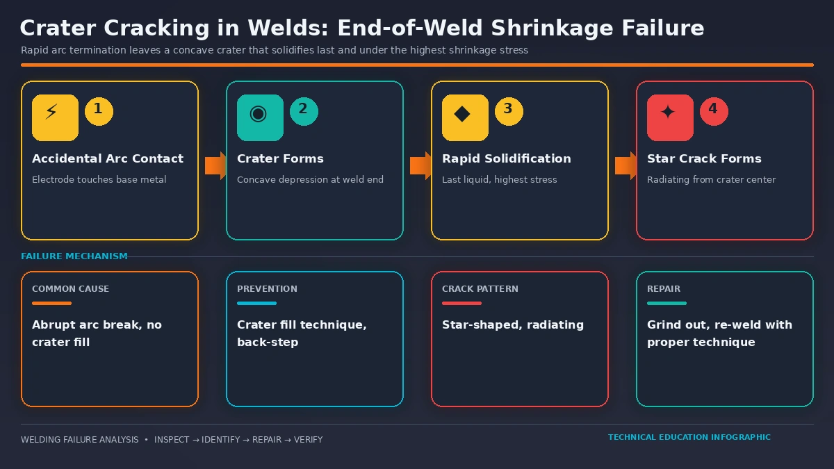
A crater crack is a crack that forms in the depression (the crater) left behind at the point where a weld bead is terminated. When the welder breaks the arc, the shielding and heat source are removed almost instantly, but the pool of molten metal underneath does not disappear with it — it continues to cool and shrink for a short period afterward. If that remaining pool is thinner or smaller in volume than the rest of the weld cross-section, which it almost always is unless deliberately compensated for, the shrinkage stress generated during solidification exceeds the strength of the still-weak, partially fused metal and the crater tears apart.
Crater cracks most commonly present in the distinctive “star crack” pattern: several short, straight fissures radiating outward from the center of the crater, resembling the points of a star. This pattern arises because the crater cools from its outer edge inward, so the last liquid to solidify sits at the geometric center, and shrinkage strain pulls symmetrically outward from that point in multiple directions at once. Not every crater crack shows this full star geometry — a single crack running back along the centerline from the crater toward the rest of the bead is also classified as a crater crack by location, even without the radial pattern.
Where Crater Cracking Fits Among Weld Defects
Crater cracking belongs to the broader family of solidification (hot) cracks, all of which occur while the weld metal is still at or near its solidus temperature and derive from the same underlying combination of shrinkage strain, insufficient liquid feed metal, and low-melting-point segregates concentrating at the solidification front. The crater is simply the location within the weld most severely exposed to all three conditions simultaneously, which is why it cracks first and most often, even in weld metal that is otherwise sound along its entire length.
Why Crater Cracks Form: The Metallurgical Mechanism
Three conditions combine at the crater, and all three must be present in some degree for cracking to occur:
1. Insufficient Liquid Weld Metal Volume
When the arc is broken abruptly, the crater is left with less filler metal than the rest of the weld bead — often a shallow dish rather than the full reinforcement profile of the completed weld. This reduced cross-section has to absorb the same total shrinkage strain as the rest of the joint but with far less material to distribute it across, so the local strain concentration rises sharply exactly where the metal is weakest.
2. Segregation of Low-Melting Impurities
As the weld pool solidifies from its outer edges inward, solute elements rejected by the growing dendrites — sulphur, phosphorus, and other trace elements depending on base metal and filler chemistry — concentrate in the last remaining liquid at the geometric center of the pool. In the crater, this center point is exactly where the crack initiates. This segregated film solidifies at a temperature below the nominal solidus of the surrounding metal, forming a thin, brittle, low-ductility boundary that has essentially no resistance to tensile strain.
3. Shrinkage Strain in the Brittle Temperature Range
All metals contract as they cool from the liquid state, and for a short window just below the solidus — the brittle temperature range — the partially solidified structure has almost no ductility to accommodate that contraction. If shrinkage strain builds faster than the material can plastically deform, the weak segregated boundaries at the crater centre simply tear apart, producing the radiating star pattern as the crack seeks the path of least resistance in several directions simultaneously.
Code definition: AWS defines a crack generally as “a fracture-type discontinuity characterised by a sharp tip and a high ratio of length and width to opening displacement.” A crater crack meets this definition at the specific location of arc termination, and under most fabrication codes it is treated with the same zero-tolerance severity as any other crack in the weldment. See our Welding Defects Complete Technical Guide for the full code-basis discussion under ISO 6520-1.
Materials and Processes Most Susceptible to Crater Cracking
While crater cracking can occur in any material and any arc welding process, susceptibility varies enormously depending on thermal conductivity, solidification range, and impurity content.
| Material / Process | Susceptibility | Primary Reason |
|---|---|---|
| Aluminum and aluminum alloys | High | High thermal conductivity accelerates cooling; wide solidification range keeps a weak mushy zone open longer |
| Austenitic stainless steel (GTAW) | Medium | Fully austenitic solidification mode is more crack-sensitive than ferritic-austenitic modes; concave crater geometry common |
| Nickel alloys (INCONEL and similar) | High | Wide freezing range and susceptibility to niobium/sulphur segregation at the solidification front |
| P91 / P92 Cr-Mo steels | High | Residual element segregation (P, S, Sb, Sn) forms brittle intergranular film; treated as zero-tolerance indicator |
| Plain carbon steel (SMAW, GMAW) | Low–Medium | Narrower solidification range than the above, but high current or excessive travel speed still produce cracking |
| High-sulphur / low-manganese steel | High | Low MnS-to-FeS ratio leaves more free sulphur to form low-melting iron sulphide films at the solidification front |
For fabricators working with crack-sensitive Cr-Mo materials, understanding welding consumable chemistry is directly relevant to crater cracking risk. Our detailed comparison of E9015-B91 vs E9018-B91 explains why residual element content in the filler metal drives exactly this failure mode, and our P91 material welding requirements guide covers the full preheat and interpass control package needed to keep P91 joints crack-free.
Quality control note for P91 and similarly crack-sensitive materials: If crater cracking is observed during procedure or production welding, do not simply grind out the crater and re-weld. On P91, a crater crack reliably indicates elevated residual element content in the filler metal batch regardless of what the certified test report states, and the entire heat of consumable should be treated as non-conforming and removed from service.
Contributing Welding Parameters
Beyond base material chemistry, the way a weld is executed strongly influences whether the crater cracks:
| Parameter / Practice | Effect on Crater Cracking Risk |
|---|---|
| Abrupt arc break with no crater fill | Leaves the crater with a thin, reduced cross-section — the single largest contributing factor |
| Excessive travel speed | Produces a narrow, elongated weld pool with a poor width-to-depth ratio that is inherently more crack-prone |
| Excessive current / high heat input | Increases the volume of molten metal and the total shrinkage strain generated as it solidifies |
| Concave bead or fillet profile | Reduces the effective throat thickness; there is not enough filler metal in the cross-section to resist shrinkage stress |
| High joint restraint | Prevents the joint from moving to relieve shrinkage strain, forcing that strain into the weakest point — the crater |
| Rapid post-weld cooling | Shortens the time available at high temperature for strain to relax plastically before the metal becomes brittle |
Practical tip: A small reduction in arc voltage (roughly 1 to 1.5 V) is often enough to correct an excessively concave bead contour that is contributing to crater and centerline cracking. Overcorrecting produces an excessively convex bead, so adjust in small increments and re-check the profile before making further changes.
Prevention Techniques
Every prevention method for crater cracking shares the same underlying goal: restore the crater to the full cross-section of the rest of the weld before the arc is broken, so the last-to-solidify region is not the weakest point in the joint.
Back-Step (Reverse Travel) Technique
At the end of the weld, the welder reverses travel direction for a short distance — typically around 10 to 15 mm (roughly 0.4 to 0.6 in) — depositing additional filler metal back into the already-completed bead before finally breaking the arc. This fills the crater to the same cross-section as the rest of the weld and moves the geometric center of the last-to-solidify liquid away from the unsupported plate edge. Back-stepping requires no special equipment and is the standard termination method for manual SMAW and GTAW.
Programmed Crater-Fill Current
Most modern GMAW and GTAW power sources include a dedicated crater-fill or downslope function that automatically ramps the welding current down over one to three seconds while the welder continues to feed filler metal (or dab filler manually in GTAW), rather than switching the arc off instantly at full current. This produces a smooth, tapered termination with a fully filled crater and is more repeatable than manual back-stepping, particularly for mechanized and robotic welding where travel speed cannot be adjusted by feel.
Run-Off Tabs (Extension Plates)
Where the joint design and drawing permit, a sacrificial run-off tab is tack-welded to the end of the joint so that the weld termination, and therefore the crater, lands entirely on material that will later be cut off and discarded. This removes the crater from the finished component altogether and is widely used in structural and pressure vessel longitudinal seam welding where a code-quality termination is otherwise difficult to guarantee.
Pause-and-Fill Technique
For manual processes without a programmed crater-fill function, simply pausing for two to three seconds at the very end of the weld — while continuing to add filler metal — before finally extinguishing the arc allows enough additional metal to build up in the crater to restore the cross-section.
Inspection and Acceptance Criteria
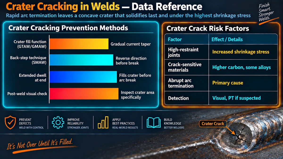
Because the crater sits at a predictable, visible location, visual testing (VT) is the first and most important line of defense. Our full welding inspection checklist specifies that every weld termination point must be examined under adequate raking light — a minimum of 500 lux at the weld surface per ISO 17637 — specifically for crater cracks and star cracking, in addition to the general crack, undercut, and profile checks applied along the rest of the bead.
Acceptance basis: Under AWS D1.1, ASME Section IX qualification testing, and most structural and piping codes, any crack — including a crater crack — found during visual, liquid penetrant, magnetic particle, radiographic, or ultrasonic examination is unconditionally rejected, as confirmed in our B31.1 visual examination acceptance standards guide. A small number of repair-oriented specifications for shallow crater or star cracks not exceeding roughly 4 mm in length permit grinding and re-welding rather than removal of the entire weld, but this exception must be explicitly stated in the governing code or client specification before it is applied.
Repair Procedure
When a crater crack is confirmed, the standard repair sequence is straightforward but must be followed exactly:
- Remove the crack completely by grinding, extending slightly beyond the visible tip in every direction.
- Confirm complete removal with liquid penetrant or magnetic particle testing before proceeding — do not rely on visual appearance alone.
- Reprofile the excavation to a smooth, gradually tapered contour with no sharp notches that could act as new stress risers.
- Apply the correct preheat and interpass temperature for the base material per the qualified WPS before re-welding.
- Re-weld using the crater-fill technique specified in the WPS, and re-inspect the repaired area by the same methods used to detect the original defect.
Repair limits: Most codes limit the number of repair attempts permitted at the same location — typically one, occasionally two with specific written approval. If a second repair attempt also fails to meet acceptance criteria, larger sections or the entire weld, including the affected heat-affected zone, must be removed and re-welded from scratch.
Frequently Asked Questions
Is a crater crack always rejectable?
Under most fabrication codes, any crack is rejectable regardless of size or location, and this includes crater cracks. Some repair-oriented specifications and certain oil and gas piping standards allow shallow crater or star cracks up to about 4 mm in length to be ground out and re-welded rather than triggering removal of the entire joint, but this exception must be explicitly permitted by the governing code or client specification. On critical materials such as P91, even a single crater crack is treated as a zero-tolerance indicator that the consumable batch itself is suspect, not just a local repair item.
What is the difference between a crater crack and a star crack?
Star cracking is simply the visual pattern that most crater cracks take: several short fissures radiating outward from the center of the crater like the points of a star. The terms are frequently used interchangeably because the star pattern is the classic signature of shrinkage-driven crater cracking. A crater crack that is not star-shaped, such as a single crack running back along the weld centerline from the crater, is still classified as a crater crack by location even though it does not show the radial star geometry.
Why is aluminum so much more prone to crater cracking than steel?
Aluminum has roughly four times the thermal conductivity and nearly double the solidification shrinkage of common structural steels, so heat leaves the weld pool very quickly and the metal contracts significantly as it freezes. Aluminum also has a wide solidification temperature range in most weldable alloys, which keeps a mushy, partially liquid zone open at the crater for longer and gives shrinkage stress more time to tear the weak, partially solidified grain boundaries apart. This is why GTAW and GMAW power sources used on aluminum almost always include a dedicated crater-fill or downslope function as standard equipment.
Does back-stepping actually prevent crater cracking, or is crater-fill current better?
Both methods work by the same underlying principle: adding enough additional filler volume at the termination point to restore the full weld cross-section before the arc is broken. Back-stepping is simple, requires no special equipment, and works on any manual process, making it the standard method for SMAW and manual GTAW. Programmed crater-fill current, which ramps amperage down over one to three seconds while continuing to feed filler, gives a more consistent and repeatable result and is preferred for GMAW and mechanized GTAW where travel speed and arc length are harder to control manually at the very end of the bead.
Can crater cracking be detected by visual inspection alone?
Surface-breaking crater cracks are frequently visible during visual testing under adequate raking light, especially the classic star pattern, and VT per our welding inspection checklist should always include close examination of every weld termination point. However, fine crater cracks can be tight enough to escape unaided visual detection, and any suspected indication at a crater should be confirmed with liquid penetrant testing. Where the crater sits over a region that cannot be fully inspected visually, or where the material is crack-sensitive such as P91 or high-strength steel, volumetric methods such as radiography or ultrasonic testing are used to rule out subsurface extension of the crack.
Are crater cracks the same as hot cracks?
Crater cracking is a specific location-based category of crack, while hot cracking (also called solidification cracking) describes the metallurgical mechanism. Most crater cracks are hot cracks, because the crater is the last region of the weld to freeze and therefore the most severely affected by segregation of low-melting impurities and shrinkage strain, exactly as described in our hot cracking guide. It is possible, though much less common, for a crater to show cold cracking if hydrogen levels are high and the joint is highly restrained, so inspectors should not assume mechanism from location alone.
Why do welding procedure specifications sometimes call out a specific crater-fill technique?
A WPS may specify the exact termination technique — back-step distance, crater-fill current profile, or mandatory run-off tabs — as an essential or nonessential variable because the technique was proven during procedure qualification testing to produce a sound weld free of crater cracks. Changing the termination method without requalifying can reintroduce the exact defect the qualification was meant to rule out, particularly on crack-sensitive materials. Welders should always follow the termination method exactly as written on the WPS rather than substituting a technique they consider equivalent.
Can a crater crack be repaired, or must the whole weld be removed?
In most cases a crater crack can be repaired locally: the crack is removed by grinding until it is confirmed absent by PT or MT, the excavation is reprofiled to a smooth taper, and the area is re-welded using a qualified repair procedure with the correct preheat. The rest of the weld does not need to be removed unless the code, the client specification, or a metallurgically sensitive material such as P91 mandates full removal because the presence of a crater crack calls the entire consumable batch or procedure into question. Most codes limit the number of repair attempts on the same location, so getting the termination technique right the first time is always cheaper than repeated rework.
Recommended Reference Books
Welding Metallurgy (Kou)
The standard graduate-level reference on solidification cracking, weld pool metallurgy, and segregation mechanisms behind crater and hot cracking.
View on AmazonWelding Inspection Handbook (AWS)
Covers visual inspection technique, crack recognition, and acceptance criteria referenced by CWI and CSWIP inspectors worldwide.
View on AmazonProcedure Handbook of Arc Welding
The Lincoln Electric classic reference covering practical termination technique, bead profile control, and defect prevention.
View on AmazonWelding Metallurgy and Weldability (Lippold)
Detailed treatment of solidification cracking susceptibility across steel, stainless, and nickel-alloy systems.
View on AmazonDisclosure: WeldFabWorld participates in the Amazon Associates programme (StoreID: neha0fe8-21). If you purchase through these links, we may earn a small commission at no extra cost to you. This helps support free technical content on this site.