Underfill and Overlap Weld Defects Explained
Underfill and overlap are two of the most frequently cited surface defects in visual weld inspection, and although they sit at opposite ends of the same spectrum — one is a deficiency of weld metal, the other an excess — both are rejectable under nearly every structural and pressure fabrication code. Recognising the difference between them, understanding why each forms, and knowing exactly how they are measured and evaluated is core knowledge for every welder, welding engineer, and QA/QC inspector.
Underfill occurs when the finished weld face or root sits below the required profile, leaving less than the design cross-section to carry load. Overlap occurs when molten weld metal flows past the fusion boundary and lays unfused on top of the base metal, creating a sharp notch at the toe that behaves like a built-in crack starter. Both defects are almost always caused by poor control of welding parameters — travel speed, current, and electrode angle — relative to the joint being welded, which is why both are entirely preventable with correct technique.
This guide covers the AWS definitions of underfill and overlap, the specific parameter combinations that cause each, how inspectors measure and evaluate them against code acceptance limits, and the practical prevention and repair methods used in the field.
Scope note: This article focuses specifically on underfill and overlap. For the complete catalogue of weld discontinuities including cracks, porosity, undercut, and lack of fusion, see the Welding Defects Complete Technical Guide. For the full visual, penetrant, magnetic particle, ultrasonic, and radiographic testing methods used to detect these defects, see our NDT methods guide.
What Is Underfill?
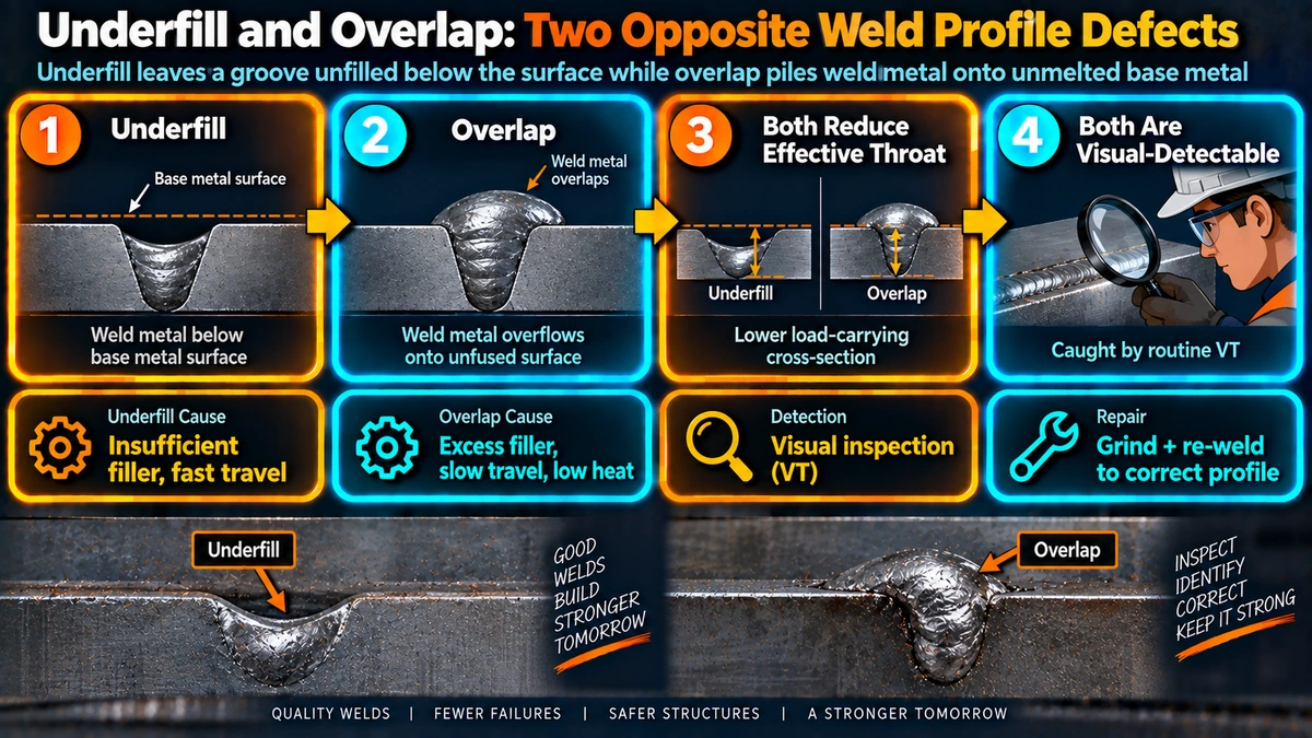
AWS defines underfill as a condition in which the weld face or root surface, at any point along its length, falls below the surface of the adjacent base metal or below the minimum reinforcement required by the applicable code or WPS. In practical terms, the welder has simply not deposited enough filler metal to bring the joint up to its full required cross-section, leaving a shallow depression running along part or all of the weld length. Underfill is most often seen on groove welds, particularly on the final capping pass, and is distinct from undercut because underfill affects the weld metal itself rather than a groove melted into the base metal at the toe.
Why Underfill Matters Structurally
The entire purpose of weld reinforcement and design throat thickness is to guarantee a cross-section capable of carrying the design load with an appropriate safety margin. Underfill directly reduces that cross-section below the value assumed in the design calculation, and because the deficiency often runs along a length of the weld rather than being a single point, the loss of load-carrying area can be significant even when the depth of the depression looks minor to the naked eye.
What Is Overlap?
AWS defines overlap as the protrusion of weld metal beyond the weld toe or weld root, where that protruding metal has not fused with the underlying base metal. Overlap forms when the molten pool spreads past the edge of the joint faster than the arc can raise the adjacent base metal to fusion temperature, so the spilled-over metal simply solidifies on top of cold base metal without ever forming a true metallurgical bond. The result is a sharp, mechanically unfused notch sitting exactly at the weld toe — already the single highest stress-concentration location in any welded joint under bending, tension, or fatigue loading.
Why overlap is worse than it looks: Overlap appears to add extra weld metal, but the overlapped region contributes zero structural strength because it never fused to the base plate. Combined with the sharp unfused notch it creates at the toe, overlap is treated by AWS D1.1 and most structural codes as rejectable regardless of the amount of “extra” metal present, and is one of the more common causes of fatigue crack initiation traced back to a specific weld defect during failure investigations.
Underfill vs Overlap: Quick Comparison
| Characteristic | Underfill | Overlap |
|---|---|---|
| Nature of defect | Deficiency of weld metal | Excess, unfused weld metal |
| Location | Weld face or root, along the bead length | At the weld toe or root, protruding onto base metal |
| Primary mechanism | Insufficient filler deposition relative to joint volume | Molten pool spills past fusion boundary onto unheated base metal |
| Typical cause | Excessive travel speed, low current, insufficient passes | Slow travel speed, excessive deposition, wrong electrode angle |
| Structural effect | Reduced load-carrying cross-section | Sharp unfused notch acting as a stress/fatigue crack initiator |
| Detection method | Visual testing with profile gauge or straightedge | Visual testing; PT confirms the unfused boundary |
| Code severity | Rejectable if below code minimum | Rejectable under AWS D1.1 |
Causes of Underfill
| Cause | Mechanism |
|---|---|
| Excessive travel speed | Not enough time for the arc to deposit sufficient filler volume as it moves along the joint |
| Low welding current | Reduced deposition rate cannot fill the joint to the required cross-section in the available passes |
| Insufficient number of passes | Groove volume calculated for the joint design is not matched by the actual filler volume deposited |
| Incorrect electrode/wire size for joint volume | Undersized consumable cannot deposit enough metal per pass without excessive passes or travel speed reduction |
| Poor welder technique on capping pass | Uneven weave or inconsistent dwell time leaves localized depressions along the finished face |
Causes of Overlap
| Cause | Mechanism |
|---|---|
| Travel speed too slow | Molten pool builds up volume faster than the arc can consume it into the joint, forcing metal to spill over the edge |
| Excessive current / deposition rate | More filler metal is delivered than the joint geometry and travel speed can absorb |
| Incorrect electrode angle | Arc force is directed away from the joint centerline, pushing molten metal toward the toe rather than into the root |
| Low current relative to travel speed | Insufficient arc energy to fuse the base metal at the joint edge, so pool metal lies on top instead of bonding |
| Improper weave pattern or excessive weave width | Weave carries molten metal beyond the fusion boundary at the extremes of each pass |
Practical tip: If overlap keeps appearing at the same position within a joint (for example, consistently at the bottom toe of a horizontal fillet), the electrode angle is almost always the first parameter to check before adjusting current or travel speed — a small angle correction directing the arc force squarely into the joint root often resolves the issue without any other changes.
Inspection and Measurement
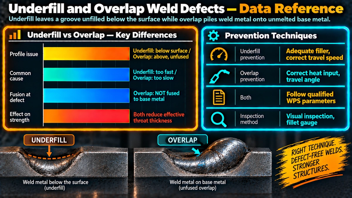
Both underfill and overlap are surface-breaking defects and are detected during routine visual testing (VT), which our NDT methods guide confirms is the mandatory first inspection step under ASME Section V Article 9 and AWS D1.1 Clause 6 before any other test method is applied.
Code reference: AWS D1.1 and ASME B31.1 both address underfill and overlap directly within their visual acceptance criteria clauses. Our B31.1 visual examination acceptance standards guide covers the full reinforcement, undercut, and linear indication limits that inspectors apply alongside underfill and overlap checks during a single VT pass.
Prevention
Preventing Underfill
Match electrode or wire size, current, and number of passes to the joint volume calculated from the WPS, and avoid pushing travel speed beyond what the deposition rate can support. On multi-pass groove welds, verify each pass has filled its intended volume before proceeding to the next, rather than relying on the final capping pass to compensate for shortfalls carried forward from earlier passes.
Preventing Overlap
Keep travel speed matched to current and deposition rate so the molten pool is consumed into the joint as fast as it is generated, maintain the correct electrode angle to direct arc force into the joint root rather than toward the toe, and avoid excessive weave width that carries molten metal past the fusion boundary. In the flat and horizontal positions, where gravity assists pool spillage, extra attention to travel speed control is particularly important.
Caution: Never attempt to “fix” visible underfill by adding a light cosmetic pass without first confirming there is no other defect — such as lack of fusion or porosity — hidden beneath the deficient area. Underfill can be a symptom of broader parameter problems on that joint, not an isolated cosmetic issue.
Repair
- Underfill: Clean the deficient area, then deposit an additional capping pass per the qualified WPS to bring the weld face up to the required profile, blending smoothly into the adjacent sound weld metal.
- Overlap: Grind away the unfused overhanging metal back to sound, fused weld metal, then blend the toe to a smooth transition profile free of sharp notches.
- Re-inspect the repaired area by visual testing, and by PT if the original defect was confirmed by penetrant testing, to verify the defect has been fully removed.
Frequently Asked Questions
Are underfill and overlap the same defect?
No, they are opposite problems that share a common cause category: poor control of filler metal deposition relative to the joint. Underfill is a deficiency of weld metal, where the finished weld face or root sits below the required profile, leaving less than the design cross-section. Overlap is an excess of weld metal that has flowed past the fusion boundary and rests unfused on top of the base metal. Both are surface-visible defects usually caught during visual testing, but they require opposite corrective actions.
Why is overlap rejectable even though it adds more weld metal, not less?
Overlap looks like extra metal but it is not structurally connected to the base metal at the overlapped region, since the flowed-over metal never reached fusion temperature with the plate surface beneath it. This creates a sharp, unfused notch exactly at the weld toe, which is already the highest stress-concentration location in any weld joint under bending or fatigue loading. Because the notch is unfused, it behaves mechanically like a crack starter rather than reinforcement, which is why AWS D1.1 and most structural codes reject overlap regardless of how much extra metal is present.
How is underfill measured during inspection?
Underfill is measured using a weld profile gauge or a straightedge laid across the weld face, checking the depth of any depression below the plane of the adjacent base metal surface or below the required minimum reinforcement height specified in the WPS or code. For groove welds, the inspector checks that the weld face is at or above the base metal surface along its full length, not just at spot checks, since underfill can be localized to short sections between weld passes. Any measured deficiency is then compared directly against the maximum permitted undersize in the governing code table.
What welding parameter is most responsible for causing overlap?
Travel speed that is too slow relative to the current and electrode angle is the single most common cause of overlap, because it allows the molten pool to build up faster than it can be consumed into the joint, forcing excess metal to spill over the fusion boundary onto cooler base metal that never reaches fusion temperature. Excessive weld metal deposition rate, incorrect electrode angle that directs the arc force away from the joint centerline, and low current relative to travel speed all compound the same underlying problem of pool volume exceeding what the joint geometry can absorb.
Can underfill or overlap be repaired without cutting out the whole weld?
Yes, both are normally surface-limited defects and are repaired locally rather than by removing the entire weld. Underfill is corrected by depositing an additional capping pass over the deficient area after proper surface preparation, following the applicable WPS. Overlap is corrected by grinding away the unfused overhanging metal back to sound, fused weld metal and then blending the toe to a smooth profile, followed by re-inspection to confirm the notch has been fully removed and no underlying defect such as lack of fusion is exposed.
Does underfill affect fatigue life the same way undercut does?
Underfill and undercut both reduce the effective load-carrying cross-section, but their fatigue effect differs because undercut also introduces a sharp notch at the toe while underfill is usually a smoother, gradual depression. This means a given depth of undercut is generally more damaging under cyclic loading than the same depth of underfill, though both reduce the section below design thickness and both are evaluated against code acceptance limits during inspection. Neither defect should be assumed acceptable without checking the governing code table for the specific joint type and loading condition.
Which welding processes are most prone to overlap?
SMAW and GMAW in the short-circuit and globular transfer modes are the processes most commonly associated with overlap, particularly in the flat and horizontal positions where gravity assists the molten pool in spilling past the joint edges. High-deposition processes such as SAW can also produce overlap if travel speed is not matched to the very high deposition rate. GTAW is less prone to overlap because filler addition is separately controlled by the welder rather than tied directly to arc current, giving finer control over pool volume at the joint edges.
Recommended Reference Books
Welding Inspection Handbook (AWS)
Covers visual inspection technique, profile measurement, and acceptance criteria for underfill, overlap, and related surface defects.
View on AmazonWelding Metallurgy and Weldability (Lippold)
In-depth treatment of weld pool behaviour, fusion mechanisms, and how parameter control drives profile-related defects.
View on AmazonProcedure Handbook of Arc Welding
The Lincoln Electric classic reference on bead profile control, electrode angle, and travel speed technique.
View on AmazonCWI Exam Prep Guide
Focused review material covering weld discontinuity recognition and code acceptance criteria for certification candidates.
View on AmazonDisclosure: WeldFabWorld participates in the Amazon Associates programme (StoreID: neha0fe8-21). If you purchase through these links, we may earn a small commission at no extra cost to you. This helps support free technical content on this site.