Slag Inclusion in Welding — Causes and Remedies
Slag inclusion is one of the most common discontinuities encountered in flux-shielded arc welding, and understanding it thoroughly is essential for any welder, welding engineer, or QA/QC inspector working with SMAW, SAW, or FCAW. Unlike defects rooted in metallurgy or joint restraint, slag inclusion is fundamentally a technique and housekeeping problem: a solid, non-metallic fragment of flux residue gets trapped inside the weld metal instead of being removed before the next pass, and it stays there as a permanent discontinuity.
Because slag inclusions arise from flux systems, they are almost entirely process-dependent — common in SMAW, SAW, and FCAW, and essentially absent in GTAW and solid-wire GMAW, which use no flux at all. This guide covers exactly how slag inclusions form, which joint geometries and welding practices increase the risk, how inspectors detect and evaluate them using radiography and ultrasonic testing, the code acceptance framework that applies, and the interpass cleaning discipline that prevents them almost entirely.
Whether you are trying to reduce rework on a multi-pass SMAW root and fill sequence or writing an inspection procedure that references RT acceptance criteria, this article gives you the complete, code-referenced picture of slag inclusion in welding.
Scope note: Slag inclusion is one of several inclusion types AWS groups together, alongside oxide and tungsten inclusions. For the complete catalogue of every weld discontinuity type, see the Welding Defects Complete Technical Guide. For how slag inclusions are visually distinguished from porosity on a radiograph, see our Welding Porosity Complete Technical Guide.
What Is a Slag Inclusion?
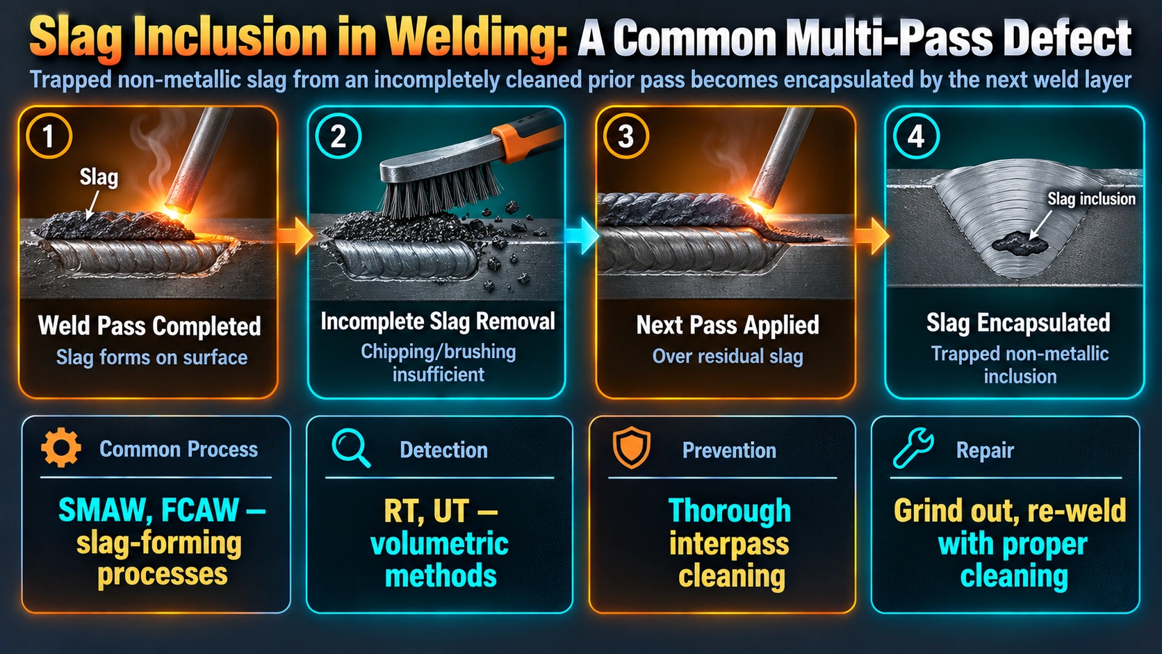
AWS defines inclusions broadly as entrapped foreign solid material, such as slag, flux, tungsten, or oxide, found within the solidified weld metal. Slag inclusion specifically refers to the trapping of solidified flux residue — the glassy or granular byproduct produced when a flux coating (SMAW), a granular flux layer (SAW), or a flux-cored wire (FCAW) reacts with the molten weld pool to shield it from atmospheric contamination and refine its chemistry. Under normal conditions this slag floats to the surface of the molten pool as it cools and is removed by the welder before the next pass, or left as a removable crust on the finished weld. When it does not fully float clear, or when the welder does not remove it before the next pass covers it over, it becomes permanently trapped inside the weld metal.
Why Slag Inclusions Are Almost Exclusive to Flux-Shielded Processes
GTAW uses inert gas shielding with no flux at all, so there is no slag byproduct to trap; solid-wire GMAW likewise relies on gas shielding rather than flux. SMAW, SAW, and FCAW all depend on a flux system to protect the weld pool and refine the deposit chemistry, which is exactly why these are the only processes where slag inclusion appears as a meaningful risk.
Susceptibility by Welding Process
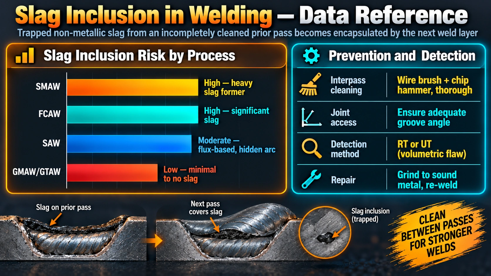
| Process | Slag Inclusion Risk | Reason |
|---|---|---|
| SMAW | High | Heavy flux coating produces significant slag volume every pass; manual technique variability |
| SAW | High | Granular flux layer fully covers the arc; slag detachability depends heavily on flux chemistry |
| FCAW (flux-cored) | Medium-High | Flux core produces slag similar to SMAW, though self-shielded and gas-shielded variants differ in volume |
| GMAW (solid wire) | Very Low | No flux system; gas-shielded process with minimal solid residue |
| GTAW | Negligible | Inert gas shielding, bare filler rod, no flux byproduct at all |
For a full comparison of how these processes differ in shielding mechanism and deposition characteristics, see our SMAW guide, SAW guide, and GTAW guide.
Causes of Slag Inclusion
| Cause | Mechanism |
|---|---|
| Inadequate interpass cleaning | Slag or oxide left on a completed pass is directly covered over and trapped by the next pass |
| Incorrect electrode angle / manipulation | Poor manipulation lets molten slag run ahead of or alongside the arc instead of floating clear behind it |
| Excessive travel speed | Weld pool freezes before slag has time to float fully to the surface |
| Low welding current | Sluggish, cooler pool increases viscosity of the slag, hindering separation from the metal |
| Narrow groove angle or root opening | Restricts access to sidewalls and root corners, making complete slag removal physically difficult |
| Poor flux detachability (SAW) | Flux chemistry that does not release cleanly from the bead surface leaves residue that can fold into the next pass |
| Undercut on the previous pass | The undercut groove becomes a pocket where slag collects and is then trapped by the next pass |
Practical tip: Pay particular attention to the toes of each completed pass, where slag pockets form most readily and are hardest to see under normal lighting. A wire brush alone is often not enough in these corners; a chipping hammer followed by a wire brush, exactly as specified in our welding inspection checklist, is the standard interpass cleaning sequence for SMAW, SAW, and FCAW.
Detection and Radiographic Appearance
Surface-breaking slag inclusions can sometimes be seen during visual testing, particularly at the final cap, but the majority of slag inclusions are subsurface and require volumetric inspection. Radiographic testing (RT) is the primary method used, since slag has a different X-ray absorption characteristic than the surrounding weld metal.
Code reference: AWS D1.1 and ASME Section VIII both apply length- and spacing-based acceptance tables to slag inclusions, broadly similar in structure to the tables applied to porosity, rather than a blanket zero-tolerance rule as used for cracks. Isolated slag indications below the maximum permitted length for the material thickness, and adequately spaced from other indications, may be accepted; indications exceeding those limits, or occurring in clusters, are rejected. See our B31.1 visual examination acceptance standards guide for the related surface-defect acceptance framework.
Prevention
Interpass Cleaning Discipline
Every pass must be fully cleaned of slag, spatter, and surface oxide before the next pass is deposited, using a chipping hammer followed by a wire brush, with particular attention to the toes of the bead where slag hides most often. This single discipline eliminates the majority of slag inclusion risk across all flux-shielded processes.
Correct Electrode Angle and Manipulation
Maintaining the correct work and travel angle keeps the arc ahead of the molten slag rather than letting slag run alongside or ahead of the pool, giving it time to float clear before the metal solidifies.
Joint Design and Access
Specifying an adequate included angle and root opening in the WPS gives the welder physical access to fully clean the root and sidewalls, particularly important in narrow-gap and tight fillet configurations. See our welding joint types guide for groove geometry considerations.
Matched Travel Speed and Current
Travel speed and current should be set so the weld pool remains fluid long enough for slag to fully separate and float to the surface, without being so slow that other defects such as overlap are introduced instead.
Caution: For SAW in particular, flux detachability is a flux-chemistry property, not just a technique issue. If slag inclusions persist despite correct technique and adequate interpass cleaning, review the flux specification and storage condition (moisture pickup can affect detachability) rather than assuming welder error.
Repair Procedure
- Locate the full extent of the inclusion using RT or UT results, and mark the excavation area with margin beyond the indicated boundary.
- Grind out the affected area completely, confirming full removal by visual inspection or PT/MT on the excavation surface.
- Reprofile the excavation to a smooth contour suitable for re-welding.
- Re-weld using the qualified WPS, with particular attention to interpass cleaning on the repair pass sequence.
- Re-inspect the repaired area by the same method (typically RT) used to originally detect the defect.
Frequently Asked Questions
What exactly is a slag inclusion?
A slag inclusion is a piece of non-metallic solid material, generally solidified flux residue, that becomes trapped inside the weld metal instead of floating to the surface and being removed before the next pass or before the weld cools. AWS classifies it under the broader inclusions category, which also covers oxide and tungsten inclusions, but slag is by far the most common inclusion type because it originates directly from the flux systems used in SMAW, SAW, and FCAW. Once trapped, a slag inclusion behaves as a discontinuity in the weld metal that reduces the effective cross-section and can act as a stress concentration point.
Why does GTAW almost never have slag inclusions?
GTAW does not use a flux-based shielding system; shielding is provided by an inert gas such as argon, and the filler rod, when used, is a bare solid wire with no flux coating. Since there is no flux present in the process at all, there is no slag byproduct to become trapped in the weld metal, which is why slag inclusions are essentially exclusive to flux-shielded processes such as SMAW, SAW, and FCAW. GTAW does have its own characteristic inclusion risk in the form of tungsten inclusions, which form by a completely different mechanism involving electrode contact with the weld pool.
How does radiography tell a slag inclusion apart from porosity?
On a radiograph, slag inclusions typically appear as elongated, irregular dark indications with rough, non-round outlines, often aligned along the direction of previous weld passes or grouped near the toes. Porosity, in contrast, appears as round or slightly elongated dark spots with smooth, well-defined edges, reflecting the spherical shape of a gas bubble rather than the random shape of a trapped solid fragment. An experienced radiographic interpreter also looks at density variation within the indication, since slag can show mottled internal density while porosity is typically uniform.
Is a single small slag inclusion always cause for rejection?
Not necessarily. Most codes, including AWS D1.1 and ASME Section VIII, apply size- and spacing-based acceptance tables to slag inclusions rather than a blanket zero-tolerance rule, similar to the approach used for porosity. A single small, isolated slag inclusion below the code’s maximum permitted length and separated by adequate distance from other indications may be accepted, but multiple inclusions in close proximity, or any inclusion exceeding the maximum linear dimension for the material thickness, will be rejected regardless of individual size.
Why does slag inclusion risk increase with a narrow groove angle?
A narrow included angle or tight root opening restricts the welder’s access to the sidewalls and root of the joint, making it physically harder to fully remove slag from the corners of the previous pass before depositing the next one, and harder to manipulate the electrode to wash out trapped slag pockets during welding itself. This is especially problematic in narrow-gap welding and in tight fillet welds, where slag can hide in the toe corners even when the welder believes interpass cleaning was thorough. Joint design that provides adequate access for both the arc and cleaning tools substantially reduces this risk independent of welder skill.
Can slag inclusions be repaired without removing the whole weld?
Yes, in nearly all cases slag inclusions are localized defects that are repaired by grinding out the affected area until the inclusion is completely removed, confirmed by visual inspection or magnetic particle/liquid penetrant testing on the excavation surface, followed by re-welding using the qualified WPS. Unlike some crack-sensitive defects, a slag inclusion does not indicate a broader material or consumable problem, so full weld removal is rarely required unless the inclusions are extensive along the joint length or the excavation exposes an additional underlying defect.
What is the single most effective way to prevent slag inclusions?
Thorough interpass cleaning — removing all slag, spatter, and oxide from every pass before depositing the next one, using a chipping hammer followed by a wire brush, with particular attention to the toes of the previous bead where slag hides most often — is the single most effective and universally applicable prevention method. Correct electrode angle and manipulation technique to allow slag to float clear of the arc, adequate joint design with sufficient access to the root and sidewalls, and matching travel speed to current so the arc consistently stays ahead of the slag all support this same underlying goal of never trapping solid material beneath fresh weld metal.
Recommended Reference Books
Welding Inspection Handbook (AWS)
Covers inclusion recognition, RT interpretation, and code acceptance criteria for slag, oxide, and tungsten inclusions.
View on AmazonSubmerged Arc Welding Handbook
Detailed treatment of flux chemistry, detachability, and slag control specific to SAW practice.
View on AmazonProcedure Handbook of Arc Welding
The Lincoln Electric classic reference on interpass technique, electrode manipulation, and defect prevention.
View on AmazonRadiographic Testing Reference Guide
Practical guide to RT film interpretation, including distinguishing slag, porosity, and lack of fusion indications.
View on AmazonDisclosure: WeldFabWorld participates in the Amazon Associates programme (StoreID: neha0fe8-21). If you purchase through these links, we may earn a small commission at no extra cost to you. This helps support free technical content on this site.