Incoming Material Checking Rules: The Complete Quality Guide for Fabrication Projects
Quality starts before fabrication. Every defect, safety incident, and costly rework that originates in a material substitution, a missing certificate, or an incorrect dimension could have been caught at the fabrication gate — before any welding, cutting, or forming was ever done. Incoming material inspection is the first and most fundamental quality control activity in any pressure vessel, piping, or structural steel project. It is the process of verifying, before materials enter your production system, that what the supplier delivered matches exactly what was ordered, what the engineering drawings require, and what the governing code demands. This guide covers all eleven incoming material checking rules systematically: from document verification at the gate through acceptance and rejection criteria at final receiving sign-off.
Document verification is performed before any physical inspection of the delivered material begins. If the documentation package is incomplete or inconsistent, the material must be quarantined until the correct documents are received — no matter how urgently production needs the material. Accepting material without complete documentation creates untraceable pressure parts, which is an unconditional code violation under ASME Section VIII, ASME B31.3, and ISO 3834-2.
- Purchase Order (PO) Checking: Verify that the delivered material matches the PO in every respect — material grade, standard, size, schedule or class, quantity, and heat treatment condition. Any deviation from the PO is a non-conformance.
- Drawing and Specification Verification: Cross-check the material against the applicable engineering drawing, piping material specification (PMS), or vessel data sheet. Confirm that the delivered product form (plate, pipe, fitting, flange) and dimensions match the drawing requirement.
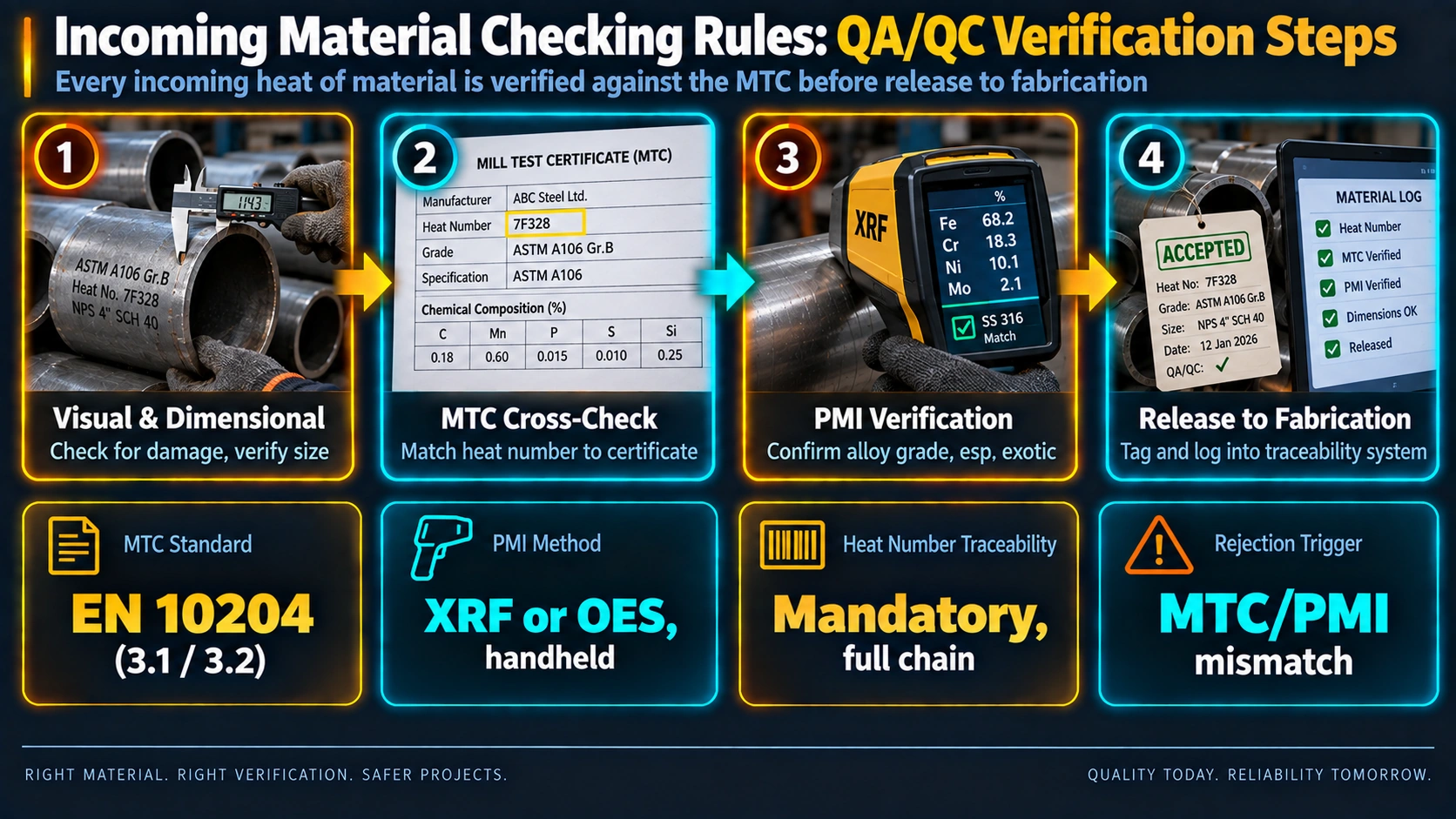
- Material Test Certificate (MTC) Review: Confirm the MTC (mill certificate) is present, covers the delivered heat number, meets the applicable ASTM / ASME material specification, and shows actual measured values (not just “meets specification” without values) for chemistry and mechanical properties.
- Heat Number Verification: Every delivered item must have the heat number physically stamped, painted, or tagged on it. Verify the heat number on the material exactly matches the heat number on the MTC. A mismatch is a mandatory rejection condition.
- Delivery Challan and Invoice Checking: Confirm quantities, item descriptions, and order references on the delivery note match the PO. Document any shortages or damaged packaging before signing the delivery receipt.
- Approved Vendor Verification: Confirm the manufacturer and supplier are on the project’s Approved Vendor List (AVL) for this material category. Material from non-approved sources must not enter the production system without formal concession approval.
Material identification bridges the gap between the paper document and the physical material. Colour coding, stamped markings, and proper labelling systems exist precisely to prevent the most dangerous type of material error: a correctly documented heat delivered alongside incorrectly identified individual pieces that have been mixed or re-marked. Positive identification must be maintained throughout the material’s entire journey from goods receiving to the weld joint.
- Material Grade Verification: Confirm the material grade marking (e.g., “A106-B” for carbon steel pipe, or “316L” for stainless pipe) matches the PO and MTC. For pressure pipe, check both the ASTM designation and the grade suffix.
- Size, Thickness, and Schedule Checking: Physically measure or verify the nominal pipe size (NPS), outside diameter (OD), and wall thickness (schedule or nominal mm) match the PO and drawing. Do not rely on supplier stencilling alone — verify with calipers or tape measure.
- Schedule / Class Checking: For pipe, verify the schedule (e.g., Sch 40, Sch 80, Sch XXS) or for fittings and flanges confirm the pressure class (150#, 300#, 600# etc.) per ASME B16.5 or B16.9.
- Colour Coding Verification: Many projects specify colour-coded end caps or paint bands for specific materials (e.g., yellow = P91, blue = 316L). Verify colour codes against the project material colour coding specification.
- Proper Marking Availability: ASME B31.3 and ASME Section VIII require material markings to be present on all pressure parts. Verify that heat number, material grade, standard, size, and manufacturer’s name or mark are legible and will be preserved through the first cut operation.
- Traceability Maintenance: Establish and record the traceability chain at receiving — item number on material register linked to MTC heat number. This chain must be maintained when material is cut: transfer heat numbers to cut pieces before the original marking area is removed.
Visual inspection of incoming material is a systematic examination of the entire delivered quantity — not a sample. Every pipe length, every plate, every fitting must be examined for the conditions listed below. Visual defects found at receiving must be formally recorded on the inspection receiving report. Borderline conditions (e.g., light surface pitting) must be assessed against the applicable product standard tolerance and the design corrosion allowance before a disposition decision is made.
- No Cracks: Surface cracks — longitudinal, circumferential, or transverse — are unconditional rejection conditions for all pressure materials. Even hairline cracks are not acceptable. Suspect areas should be examined by MT or PT.
- No Dents or Bends: Mechanical damage from handling, shipping, or stacking that has deformed the material cross-section. Dents in pipe are particularly critical as they alter the OD geometry and may introduce residual stress or local thinning.
- No Corrosion or Excessive Rust: Light surface oxidation (flash rust) on carbon steel is normally acceptable and will be removed during joint preparation. Heavy pitting corrosion, black scale, or any corrosion on stainless steel or alloy material is not acceptable — reject.
- No Lamination or Edge Damage: Lamination is a subsurface planar discontinuity in plate material visible at cut edges as a separation parallel to the plate surface. Laminated material must be rejected — it cannot be detected by visual inspection alone at the plate surface; always examine cut edges and use UT on suspect material.
- Proper Coating and Paint Condition: Where materials are supplied with factory-applied internal or external coating (FBE, epoxy, paint), verify the coating is undamaged, continuous, and matches the specification. Holiday testing or DFT measurement should be performed on critical-service coated pipe.
- Thread Condition Checking: For threaded pipe, fittings, nipples, and instrument connections, verify thread form, pitch, and engagement length. Damaged, crossed, or out-of-tolerance threads are a rejection condition — pressure connections must form a leak-tight joint.
Dimensional inspection at receiving confirms that the material as-delivered will fit into the piping system or pressure vessel as designed. Piping and fittings that are outside dimensional tolerance create fit-up problems — incorrect root gaps, high-low misalignment beyond code limits, and interfering geometries — that either produce weld defects or require costly rework. All dimensional measurements must be recorded on the receiving inspection report with actual measured values, not simply “passed”.
- Length Verification: For cut-to-length pipe or plate, verify the delivered length against the PO tolerance. For standard mill-length pipe, confirm all lengths are within the applicable ASTM standard length tolerance.
- OD and ID Checking: Measure the outside diameter at a minimum of two perpendicular axes at each pipe end and at mid-length. For ASME B31.3 pressure pipe, verify OD is within the ASTM tolerance for the nominal size. Ovality (difference between max and min OD at any cross-section) must be within tolerance for the applicable product standard.
- Thickness Measurement: Measure wall thickness using ultrasonic wall thickness gauge at multiple circumferential locations on each pipe length, and at multiple locations across plate surface. Minimum measured thickness must not be less than the minimum ordered thickness per the applicable ASTM tolerance (typically nominal minus 12.5% for seamless pipe per ASTM A106).
- Flange Dimension Checking: For flanges, verify bore diameter, raised face diameter, bolt hole circle diameter (PCD), bolt hole diameter, quantity of bolt holes, flange face finish (RF, FF, RTJ), and overall flange dimensions against ASME B16.5 or B16.47 as applicable.
- Bolt Hole and PCD Verification: Use a bolt hole PCD gauge or vernier caliper to verify that bolt holes are correctly positioned on the bolt circle. Even a single bolt hole out of position will prevent the flange from bolting up correctly in the field — a problem that may not be discovered until erection.
- Straightness and Roundness Checking: For pipe, check straightness by rolling on a flat surface or using a straight edge. For plate and structural, check for camber and bow. Out-of-straight material requires correction before use or must be rejected if correction is not feasible within tolerance.
The Material Test Certificate (MTC) is not just a piece of paper — it is the legally and technically binding document that proves the material meets its specification. Verifying the MTC requires checking not just that the document exists, but that every individual test result is within the specification limits, and that the test methods used comply with the applicable ASTM or ASME material standard. A fabricator who accepts a material solely on the basis of a supplier’s statement of compliance without verifying the MTC values has not performed proper incoming inspection.
- Chemical Composition Checking: Verify all reported element percentages against the ASTM/ASME specification maximum and minimum limits. Pay particular attention to carbon content (affects weldability and PWHT requirements), sulphur and phosphorus (embrittlement risk), and chromium/molybdenum content in alloy steels.
- Mechanical Properties Verification: Check that tensile strength, yield strength, elongation, and reduction-in-area values all meet specified minimums. For low-temperature service, verify Charpy impact test results at the specified test temperature and that they meet the code minimum absorbed energy requirement.
- Hardness Testing: Where hardness is specified (e.g., for sour service per NACE MR0175 — max 22 HRC / 248 HV), confirm the MTC reports hardness values and they are within limits. For P91, verify the hardness falls within the tempered martensite range (typically 187–248 HBW).
- Code Compliance Verification: Confirm the material standard and grade listed on the MTC are permitted materials under the applicable design code (ASME Section VIII, B31.3, B31.1). Verify the product specification level (PSL) where required (e.g., API 5L for line pipe in Category M fluid service under B31.3).
- Heat Treatment Condition: Verify the heat treatment condition stated on the MTC matches what the specification requires — normalised, quenched and tempered, solution annealed, etc. For P91 (SA-335 P91), confirm the MTC states normalising and tempering were performed and that the final Cr and Mo content is within the enhanced B31.3 range if required.
Alloy material substitution — a wrong alloy delivered in place of a specified alloy — is one of the most dangerous failure modes in process plant construction. In many cases, carbon steel and low-alloy steel pipe look identical to the eye: the only way to distinguish SA-106 Gr.B carbon steel from SA-335 P22 or P91 Cr-Mo alloy steel is by composition analysis. The consequence of using the wrong alloy in a high-temperature service application includes accelerated creep damage, hydrogen attack, and rupture during service. PMI is not optional for these materials.
| Material | ASME P-No. | Key Alloying Elements | PMI Check Points | Additional Requirements |
|---|---|---|---|---|
| P11 (1.25Cr-0.5Mo) SA-335 P11 / SA-387 Gr.11 | P-No. 4 | Cr: 1.00–1.50% Mo: 0.44–0.65% | Cr and Mo content by XRF or OES; confirm not carbon steel | PWHT verification; hardness ≤241 HBW; preheat required for welding |
| P22 (2.25Cr-1Mo) SA-335 P22 / SA-387 Gr.22 | P-No. 5A | Cr: 1.90–2.60% Mo: 0.87–1.13% | Cr and Mo content; distinguish from P11 and carbon steel | PWHT at 675°C min per ASME IX; hardness ≤241 HBW; temper embrittlement assessment |
| P91 (9Cr-1Mo-V) SA-335 P91 / SA-387 Gr.91 | P-No. 15E | Cr: 8.0–9.5% Mo: 0.85–1.05% V: 0.18–0.25% | Cr (distinguish P91 from P22 and SS316); V content confirms P91 vs P92 | PWHT 730–800°C mandatory; hardness 187–248 HBW; full chemistry per enhanced requirements |
| SS 304/304L SA-312 TP304L | P-No. 8 | Cr: 18–20% Ni: 8–10.5% C: ≤0.03% (L) | Cr and Ni content; confirm 304L vs 316L (no Mo in 304) | Solution annealed condition; no sensitisation; delta ferrite content for castings/welds |
| SS 316/316L SA-312 TP316L | P-No. 8 | Cr: 16–18% Ni: 10–14% Mo: 2.0–3.0% | Cr, Ni, and Mo content; Mo presence confirms 316 vs 304 | Solution annealed; verify L grade for weld decay service; ASTM G48 for pitting corrosion qualification |
- PMI Testing: Perform XRF or OES PMI on a minimum of 10% of pipe lengths, 100% of fittings and flanges for alloy materials (or as specified by the project PMI plan per API RP 578). Record PMI results against the heat number on the material register.
- Hardness Testing: Verify bulk hardness of received alloy materials — particularly P91 — is within the expected as-received range. P91 incorrectly heat treated (not normalised and tempered) may arrive at incorrect hardness and must be rejected.
- PWHT Verification (for pre-treated components): For alloy components supplied in the post-weld heat treated condition (e.g., pre-welded sub-assemblies), verify that PWHT was performed and that the PWHT chart and temperature records are included in the documentation package.
- NDT Verification: For critical alloy pressure parts, confirm that any NDT (RT, UT, MT, PT) required by the product specification or purchase order has been performed and that the test reports are included with the MTC package.
Welding consumables — SMAW electrodes, TIG filler wire, MIG wire, SAW wire and flux, FCAW wire — are materials that become part of the permanent weld metal in the pressure boundary. They require the same level of incoming traceability, certification review, and physical condition inspection as base materials, yet are frequently treated as general consumable items. This is a significant quality risk: the wrong electrode grade, a damp low-hydrogen electrode, or an expired batch can introduce weld metal chemistry non-compliance, hydrogen cracking, or porosity into welds that cannot be detected until expensive NDE is performed.
- Electrode Grade Verification: Confirm the AWS electrode classification (e.g., E7018-H4, E8018-B2, E316L-16) matches the WPS requirement for the base material and service. Check the electrode packaging and data sheet — do not rely on the box label alone as restamped or counterfeit electrodes are a known industry problem.
- Filler Wire Checking: For TIG (GTAW) filler wire and MIG (GMAW) wire, verify the AWS classification (e.g., ER70S-6, ER316L, ER90S-B3) against the applicable WPS. Verify diameter matches WPS specification.
- Batch Number Verification: Each delivered batch of consumables must have a batch or lot certificate from the manufacturer showing the chemical composition of the deposited weld metal and the mechanical properties of test welds made with that batch. File batch certificates with the welding documentation for the project.
- Oven Temperature Checking: Low-hydrogen electrodes must be placed in a rod oven at 120–150°C immediately on receipt. Verify that the rod oven is functioning and at the correct temperature using a calibrated thermometer. Log the receipt date and oven entry date for every batch.
- Proper Storage Condition: Verify storage facilities: rod ovens for low-hydrogen SMAW electrodes; dry sealed containers for TIG wire; humidity-controlled stores for flux; ambient storage for cellulosic electrodes (E6010/E6011). Reject any consumables that show moisture damage, rust on the wire, damaged flux coating, or expired shelf life.
Many material specifications and project quality plans require the material manufacturer to perform non-destructive testing on the finished product before dispatch. This is particularly common for seamless pressure pipe (UT for wall thickness and seam defects under ASTM E213/E309), pressure vessel plates (UT for laminations per ASTM A578), and fittings and flanges (UT, MT, or PT per product standard). At incoming inspection, the QC engineer must verify that all required NDT was actually performed, that the test reports are attached to the MTC package, and that all results are within the acceptance criteria of the applicable standard.
- RT Report Checking: For weld seams in ERW (Electric Resistance Welded) or EFW (Electric Fusion Welded) pipe, or for pressure vessel plate butt welds supplied as sub-assemblies, verify RT or digital radiography reports showing seam weld quality meets the acceptance criteria of the applicable standard.
- UT Report Checking: Verify UT reports for wall thickness and volumetric examination. For P91 pipe, confirm UT was performed per the ASME SA-335 specification supplementary requirements (S3, S5, S10) where specified in the purchase order.
- PT/MT Report Verification: For forgings (flanges, fittings) and castings, verify that PT or MT was performed as required by the product standard. Check that the examination covered the required surfaces and that the report references the applicable acceptance standard.
- Acceptance Criteria Confirmation: Verify that the acceptance criteria cited in each NDE report match the applicable code or specification. A report that simply states “accepted” without referencing a specific acceptance standard is not acceptable — the criterion must be traceable.
- Calibration Validity Checking: Confirm that the NDE equipment calibration records cited in the reports were valid at the time of examination. Calibration certificates for UT equipment, radiographic source activity, and reference blocks must all be within their stated calibration periods.
Material that passes incoming inspection can still be degraded before it reaches the welding station if it is not stored and handled correctly. Storage failures — particularly mixed material storage or unprotected outdoor storage — have caused catastrophic failures in completed equipment because contamination introduced during storage is invisible after fabrication. A robust material storage and preservation system is not an overhead: it is a quality investment that protects all the work done during receiving inspection.
- CS and SS Separate Storage: Carbon steel and stainless steel (and other corrosion-resistant alloys) must be physically separated — different storage bays, separate racks, dedicated lifting equipment for each material family. Iron contamination from carbon steel contact destroys the passive layer of stainless steel and is invisible until corrosion develops in service.
- Wooden or Rubber Support Usage: All pipe and plate must be stored off the ground on wooden dunnage (carbon steel) or rubber/nylon-covered supports (stainless steel and alloys). Direct ground contact causes localised corrosion and contamination, and may make heat number identification difficult.
- Rain and Moisture Protection: Alloy materials, stainless steel, and low-hydrogen welding consumables must be protected from precipitation and condensation. Cover stored material with tarpaulins or store under cover. Moisture-sensitive materials (P91 pipe, SS sheet) should be stored indoors.
- End Cap Protection: All pipe must be stored with factory end caps in place or replacement plastic end caps fitted. Open pipe ends allow moisture, dirt, insects, and debris to enter the bore — contamination that is extremely difficult to clean out before welding and creates porosity and inclusion defects.
- No Direct Ground Contact: This applies to all materials without exception. Even for temporary lay-down during receipt processing, use wooden sleepers or rubber mats. Ground contact introduces chloride contamination on stainless steel and creates crevice corrosion in anaerobic conditions on all alloys.
Material acceptance is a formal decision — not an informal understanding between site personnel. A completed Receiving Inspection Report (RIR) signed by the responsible Quality Control Inspector is required before any material can be tagged “ACCEPTED” and released to the material storage system. Material is accepted only when all of the following six conditions are satisfied without exception. The acceptance decision is binary: all six pass, or the material is placed in quarantine pending resolution.
| Acceptance Condition | Verification Method | If Not Met |
|---|---|---|
| PO Matches | Cross-reference delivered material grade, size, quantity, and standard against the Purchase Order line item | Quarantine — contact procurement for supplier clarification before any physical disposition |
| MTC Available and Valid | MTC present, heat number matches material, all specified test values within specification limits | Quarantine — request correct MTC from supplier; do not accept generic or photocopy MTC without original or certified true copy |
| Dimensions Acceptable | All dimensional measurements within PO tolerance, drawing dimension, and product standard dimensional tolerance | Raise NCR; obtain concession approval from engineering if borderline; reject if outside tolerance |
| No Visual Defects | 100% visual inspection per Rule 3 — no cracks, excessive corrosion, damage, or coating failure | NCR raised; segregate affected pieces; obtain engineering disposition; likely rejection |
| NDT / PMI Acceptable | All required NDT reports present and results within acceptance criteria; PMI results within specified composition range for alloy materials | Unconditional rejection — wrong chemistry or failed NDT cannot be dispositioned as use-as-is |
| Proper Traceability Maintained | Heat number legible on each item; material register updated with heat number, MTC reference, and received quantity; colour coding applied if required | Perform positive material identification; if traceability cannot be re-established, reject — unidentified pressure parts cannot be used |
Rejection is not a negative outcome — it is the system working correctly. The purpose of incoming inspection is to catch non-conforming material before it enters the production system, not after. A rejection at the gate costs a supplier conversation and a replacement delivery. The same non-conformance caught after fabrication costs rework, re-NDE, schedule delay, and potentially vessel rejection or plant shutdown. Material that meets any of the following seven rejection conditions must be immediately physically tagged with a red REJECTED label, segregated from all accepted and uninspected material, and formally dispositioned through a Non-Conformance Report (NCR).
- Wrong Material Grade: The delivered material is a different grade than specified — e.g., SA-106 Gr.A delivered instead of Gr.B, or carbon steel pipe instead of P22. Wrong grade material may have insufficient strength, wrong weldability, or unacceptable service properties. Unconditional rejection — no use-as-is concession is possible for a grade substitution on a pressure part without full engineering re-analysis and code compliance review.
- Missing MTC: The MTC is absent, covers a different heat number, or does not cover the required test values. Material without a valid MTC is untraceable and uncertified — it cannot legally be used as a pressure part under ASME, API, or ISO 3834 systems. No exceptions.
- Heat Number Mismatch: The heat number physically marked on the material does not match the heat number on the MTC. This may indicate a labelling error — or it may indicate material substitution. Either way, the material cannot be accepted until positive material identity is established by the manufacturer or through PMI and mechanical testing. If positive identity cannot be established, reject.
- Failed PMI/NDT: PMI results show the material composition is outside the specified range (e.g., XRF shows Cr content inconsistent with claimed alloy grade), or NDT reports show rejectable defects (laminations, cracks, excessive wall thinning). These are unconditional rejection conditions — material integrity or identity cannot be confirmed.
- Excessive Corrosion: Corrosion or pitting that, when measured, exceeds the maximum pitting depth or minimum remaining wall thickness permitted by the product standard or by the design minimum thickness plus corrosion allowance. Heavy rust that cannot be fully removed to expose a sound metal surface is also a rejection condition for materials to be welded.
- Dimension Out of Tolerance: Any measured dimension (OD, wall thickness, length, bolt hole PCD, flange bore, straightness) that falls outside the tolerance specified on the engineering drawing, PO, or applicable product standard. Dimensional non-conformances may be dispositioned as use-as-is by engineering concession in some cases — but this requires formal engineering review and written concession, not an informal field decision.
- Transport Damage Found: Significant mechanical damage caused during transport — severe dents, crushed or bent pipe ends, deformed flange faces, broken threads, or impact damage to coatings that may have caused underlying material cracking. Minor transport marks that do not affect dimensional or fitness-for-service requirements may be accepted by engineering concession; significant damage is a rejection condition.
Common Inspection Tools for Incoming Material Checking
Effective incoming material inspection requires calibrated, maintained instruments. All instruments used for dimensional measurement must have valid calibration certificates that are checked before use. Calibration records must be maintained in the quality system.
Vernier Caliper
OD, ID, wall thickness, and dimensional checks on flanges, fittings, and pipe ends. Resolution: 0.02 mm (analogue) or 0.01 mm (digital).
Measuring Tape / Steel Rule
Length verification, flange diameter, bolt hole spacing on PCD. Ensure tape is calibrated and not kinked or damaged.
UT Wall Thickness Gauge
Measures pipe and plate wall thickness from one side using pulse-echo ultrasound. Required for minimum thickness verification without requiring the pipe bore to be accessible.
PMI Machine (XRF Analyser)
X-ray fluorescence PMI for non-destructive alloy composition verification. Identifies alloy grade in seconds. Required for P11, P22, P91, SS304, SS316, and all alloy materials.
Hardness Tester
Portable Vickers (HV), Brinell (HBW), or Rockwell (HRC) testers for hardness verification at receiving. Critical for sour-service materials and P91 heat treatment verification.
Optical Emission Spectrometer (OES)
More precise alloy composition analysis than XRF, particularly for light elements (C, Si, P, S). Used for final chemistry confirmation on critical alloy grades when XRF results are borderline.
Remember — The Incoming Inspection Principle
Quality is not inspected into the product after fabrication.
It starts with correct incoming material checking.
Right Material. Right Inspection. Right Quality. Safe Project.
Recommended Reference Books on Material Inspection and Piping Codes
Frequently Asked Questions
What is an incoming material inspection and why is it required?
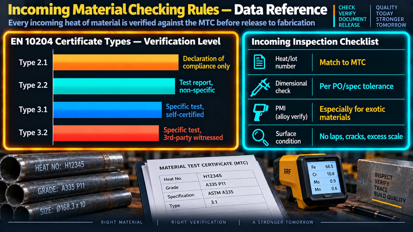
Incoming material inspection is a formal quality control activity performed when materials arrive at a fabrication facility before they are released for use in production. It verifies that the delivered material matches the purchase order specification, drawing requirements, and applicable code requirements in terms of grade, dimensions, heat treatment condition, surface quality, and documentation completeness. It is required by ISO 9001, ASME Section VIII, ASME B31.3, and ISO 3834-2, and by most owner and EPC project quality specifications. Fabricating with incorrect or uncertified material can result in catastrophic equipment failure, legal liability, and costly rework or scrapping of completed assemblies. As the image in this guide states — quality is not inspected into the product after the fact; it starts with correct incoming material checking.
What is a Material Test Certificate (MTC) and what should it contain?
A Material Test Certificate (MTC) is a document issued by the material manufacturer certifying that the supplied material meets the specified standard. It must contain the material standard and grade, heat number, product form and dimensions, chemical composition (actual measured values for all specified elements), mechanical test results (tensile strength, yield strength, elongation, hardness, and impact values where required), heat treatment condition, and the authorised signatory. For ASME pressure vessel and piping applications, the MTC must comply with ASTM A20 for plates, ASTM A530 for pipes, or the applicable product specification. The heat numbers on the certificate must exactly match the markings physically stamped or stencilled on the delivered material — any mismatch is a mandatory rejection condition requiring immediate quarantine.
What is PMI testing and when is it required?
Positive Material Identification (PMI) is a non-destructive technique that verifies the chemical composition of a material using X-ray fluorescence (XRF) or optical emission spectrometry (OES). It confirms the alloy identity against the MTC, detecting material mix-ups that are invisible to the eye. PMI is required for alloy materials where grade substitution is a safety risk: chromium-molybdenum steels (P11, P22, P91), stainless steels (304, 316, 316L, 321), duplex stainless steels, and nickel alloys. It is mandated by API RP 578 for hydrocarbon process piping and is increasingly required by EPC and owner specifications for all alloy pressure parts at receiving. A minimum of 10% of pipe lengths and 100% of fittings and flanges for alloy materials is a common starting requirement — project PMI plans define the exact coverage.
Why must carbon steel and stainless steel be stored separately?
Carbon steel and stainless steel must be physically separated because carbon steel particles — rust, scale, iron filings from grinding or cutting nearby — can contaminate stainless steel surfaces and embed in the passive oxide layer that gives stainless steel its corrosion resistance. Once iron-contaminated, the stainless steel surface develops rust spots and loses its passivity. This is called ferritic contamination and it cannot be repaired by simple cleaning — the contaminated surface must be pickled and passivated or the material replaced. Additionally, different lifting equipment must be used: carbon steel wire slings leave iron deposits on stainless steel surfaces. This storage rule is not industry best practice — it is a hard requirement under most stainless steel fabrication quality standards and project specifications.
What are the mandatory rejection conditions for incoming material?
Material must be unconditionally rejected and quarantined on any of the following: wrong material grade; missing or incomplete MTC; heat number mismatch between MTC and physical marking; failed PMI (composition outside specification); failed NDT (rejectable defects); excessive corrosion beyond acceptance limits; dimensions outside tolerances; or transport damage rendering the material unfit for service. Rejected material must be physically tagged with a red rejection label, moved to a separate quarantine area, and formally dispositioned through a Non-Conformance Report (NCR). No person below the QC Manager level may override a material rejection decision, and no informal dispositions such as “set it aside and we’ll sort it out later” are acceptable under any quality management system.
What standards govern incoming material inspection for piping and pressure vessels?
The primary governing standards are ASME BPVC Section II (material specifications), ASME B31.1 (power piping), ASME B31.3 (process piping — material identification and traceability requirements), ASTM product standards (A105, A106, A516, A312, A790, etc.) defining chemical and mechanical test requirements and MTC format, API RP 578 for PMI of alloy piping in hydrocarbon service, and ISO 10474 for inspection document formats. Owner and EPC project quality plans typically impose additional requirements. ASME B31.3 paragraph 305.2 specifically requires that all pressure-containing materials be identified by material specification, grade or class, heat number, and that a record be maintained that allows the material to be traced to its certificate. See also the P-Number material grouping guide for the ASME classification system for pressure vessel materials.
What is a heat number and why does traceability to it matter?
A heat number (or cast number) is a unique identifier assigned by the steel mill to a specific batch of steel produced in one melting furnace heat. The MTC covers one heat, and all test results on the MTC represent that heat’s actual chemistry and properties. Traceability means the ability to link every piece of pressure-containing material in a completed vessel or piping system back to its original MTC through the heat number — confirming that the material in service is the material that was tested. This linkage is required by ASME Section VIII UG-93 and ASME B31.3 paragraph 305.2.1 and must be maintained through every operation: heat numbers must be transferred to cut pieces before the original marking area is removed. Loss of traceability is a code violation and requires the material to be re-qualified or rejected.
What storage and preservation rules apply to welding consumables?
Welding consumables require the same care as base materials. Low-hydrogen SMAW electrodes (E7018, E8018, E9018) must be stored in a heated rod oven at 120–150°C and rebaked at 300–350°C for 1 hour before use on critical joints to prevent moisture absorption and resulting hydrogen-induced cracking. Filler wire must be stored in sealed containers or humidity-controlled stores. SAW flux must be stored dry. All consumables must be traceable to their batch certificate, which must be verified against the AWS classification required by the applicable WPS. Damaged, corroded, wet, or unbaked low-hydrogen electrodes must never be used on pressure-containing welds. Consumable storage records (including oven temperature logs and issue-from-oven records) are part of the welding quality documentation system. See the complete welding documentation guide for full consumable record requirements.