Welding Parameters Guide: Mastering Current, Voltage, and Heat Input
Welding parameters — current, voltage, travel speed, polarity, shielding gas, and electrode angle — are the controllable variables that determine whether a weld meets its structural, metallurgical, and quality requirements. Get them right and you produce strong, defect-free joints with the correct weld geometry and heat-affected zone. Get them wrong and the consequences range from cosmetic blemishes to catastrophic failure: porosity, lack of fusion, hot cracking, burn-through, or a heat-affected zone that has been embrittled or sensitised.
For welding engineers and inspectors, parameters are not merely machine dial settings. They are the primary variables captured on a Welding Procedure Specification (WPS) and Procedure Qualification Record (PQR), and they directly control heat input — the single most important calculated quantity in code-governed fabrication. Heat input drives weld pool size, cooling rate, HAZ microstructure, residual stress, and distortion. Understanding how each parameter contributes to heat input, and how to calculate it correctly per ASME IX and AWS D1.1, is essential knowledge for any CWI or fabrication engineer.
This guide covers all primary welding parameters from first principles, explains how they interact, provides a free online heat input calculator with a step-by-step worked breakdown, and includes process-specific reference tables for SMAW, GMAW, GTAW, FCAW, and SAW. Whether you are optimising a production welding procedure or troubleshooting weld defects on site, this is your technical reference.
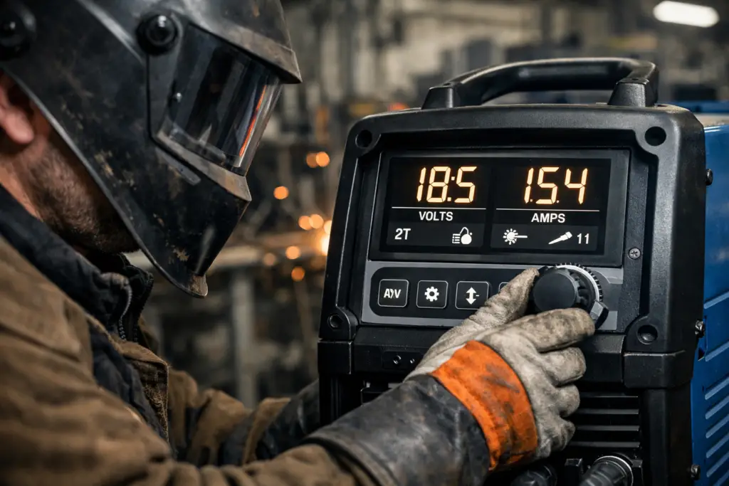
Heat Input Calculator
Calculates heat input per ASME BPVC Section IX / AWS D1.1 with thermal efficiency factor k. Enter your process parameters below.
What Are Welding Parameters?
Welding parameters are the controllable process variables documented on a Welding Procedure Specification (WPS) that together determine the thermal and mechanical behaviour of the weld. They are classified as either essential variables — changes to which require requalification of the WPS under ASME Section IX or ISO 15614 — or non-essential variables, which can be adjusted within specified ranges without requalification.
The primary welding parameters are current (amperage), voltage, travel speed, polarity, electrode/filler wire classification, shielding gas composition and flow rate, electrode angle, preheat and interpass temperature, and for wire-feed processes, wire feed speed and electrode extension (stick-out). Secondary parameters such as nozzle diameter, joint geometry, and backing condition also influence the weld but are typically captured as supplementary variables on the WPS.
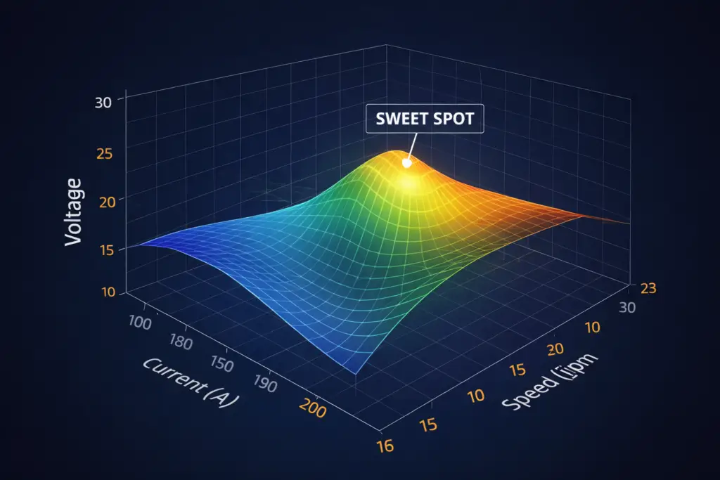
Taken together, current, voltage, and travel speed define heat input — the most significant single quantity in controlled fabrication, because it governs cooling rate, HAZ microstructure, the width of the weld bead, distortion, and residual stress. The heat input calculator above allows you to compute this value for any process combination.
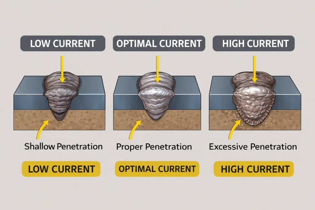
Welding Current (Amperage)
Welding current, measured in amperes (A), determines the rate of heat generation at the arc and directly controls penetration depth and deposition rate. It is the most influential single parameter in most arc welding processes and is therefore designated as an essential variable in qualification codes.
Effect of Current on Weld Quality
| Current Condition | Penetration | Bead Width | Deposition Rate | Typical Defect Risk |
|---|---|---|---|---|
| Too high | Excessive | Wide, flat | High | Burn-through, undercut, spatter |
| Correct range | Adequate | 2–3 × electrode dia. | Optimal | Defect-free (with correct other parameters) |
| Too low | Insufficient | Narrow, convex | Low | Lack of fusion, cold laps, arc instability |
Current Ranges for Common Electrode Sizes (SMAW, Mild Steel)
| Electrode Dia. (mm) | Electrode Dia. (in) | Flat Position (A) | Vertical Up (A) | Overhead (A) |
|---|---|---|---|---|
| 2.5 | 3/32 | 60–90 | 55–80 | 55–80 |
| 3.2 | 1/8 | 90–150 | 80–130 | 80–130 |
| 4.0 | 5/32 | 130–190 | 110–160 | 110–160 |
| 5.0 | 3/16 | 180–260 | Not recommended | Not recommended |
| 6.4 | 1/4 | 240–350 | Not recommended | Not recommended |
Arc Voltage
Arc voltage controls the arc length and the width of the weld bead. In most arc welding processes, arc length and voltage are directly proportional — increasing arc length raises voltage. The relationship between voltage and current defines the arc characteristic, which determines metal transfer mode in GMAW processes.
Voltage Effects on Weld Characteristics
Higher arc voltage produces a flatter, wider bead with less penetration and is associated with increased spatter and, if taken too far, undercut and porosity. Lower arc voltage creates a narrower, more convex bead with deeper penetration. Voltage that is too low in SMAW causes the electrode to stub into the workpiece; in GMAW it forces the wire short-circuit aggressively, producing an irregular, spattery weld pool.
Voltage in SMAW: Arc Length Control
In SMAW (stick welding), the welder does not set voltage independently — it is established by the arc length maintained during welding. The widely applied rule is that arc length should equal the electrode core diameter. A 3.2 mm electrode therefore requires an arc gap of approximately 3.0–3.5 mm, producing arc voltages in the range of 20–26 V depending on the electrode classification and base current.
Voltage in GMAW: Arc Transfer Modes
In MIG welding, voltage is independently adjustable and controls the metal transfer mode in combination with wire feed speed and shielding gas composition. The three principal transfer modes and their typical parameter ranges for 1.2 mm ER70S-6 wire on mild steel are:
| Transfer Mode | Voltage (V) | Current (A) | Gas | Application |
|---|---|---|---|---|
| Short Circuit | 15–22 | 60–180 | CO2 or Ar/CO2 | Thin sheet, root passes, all positions |
| Globular | 22–28 | 180–280 | CO2 or Ar/CO2 | Flat/horizontal fillet (transitional, higher spatter) |
| Spray | 26–36 | 250–500+ | 80%+ Ar mix | Thick material flat/horizontal, high deposition |
Travel Speed
Travel speed is the rate at which the electrode or torch is moved along the joint, typically expressed in mm/min (metric) or in/min (imperial). It is the third variable in the heat input formula and has an inverse relationship with heat input: increasing travel speed while holding current and voltage constant reduces heat input proportionally.
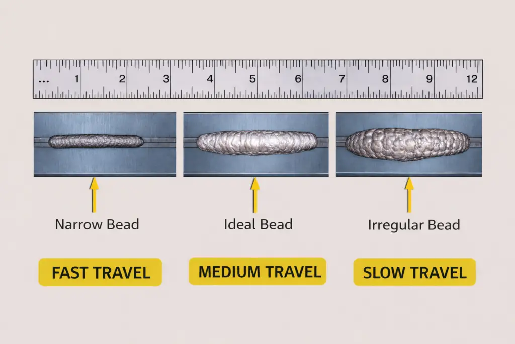
Travel Speed Effects Summary
| Condition | Heat Input | Bead Width | Penetration | Defect Risk |
|---|---|---|---|---|
| Too fast | Low | Narrow, convex | Shallow | Lack of fusion, undercut, cold lap |
| Correct | Specified range | 2–3 × electrode dia. | Adequate | Defect-free |
| Too slow | High | Wide, flat | Excessive | Burn-through, distortion, sensitisation (SS) |
Heat Input: Formula, Code Requirements, and Worked Example
Heat input is the key calculated parameter in code-governed fabrication. It is captured on the WPS as both a minimum (to ensure proper fusion and preheat effectiveness) and a maximum (to prevent grain coarsening, HAZ embrittlement, and sensitisation). For materials such as P91 Grade 91 creep-resistant steel and duplex stainless steels, heat input limits are especially critical to microstructure control and must be strictly observed in production.
Welding Polarity
Polarity determines the direction of current flow through the welding circuit and has a significant effect on penetration, deposition rate, and arc stability. It is set by the welder before starting and must match the electrode or wire classification requirements.
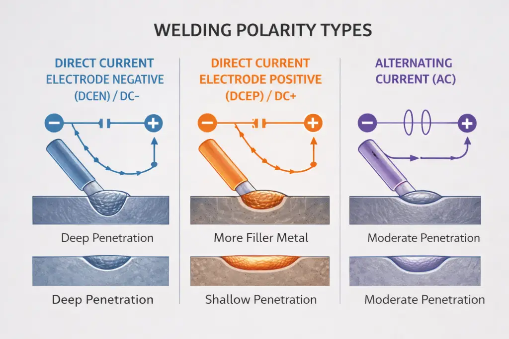
| Polarity | Electrode Connection | Penetration | Deposition Rate | Typical Processes |
|---|---|---|---|---|
| DCEP (Reverse Polarity) | Electrode = +ve | Deep | Moderate | SMAW most electrodes, GMAW MIG, FCAW-G |
| DCEN (Straight Polarity) | Electrode = −ve | Shallow | High | GTAW TIG (steel/SS), SMAW E7024 high dep. |
| AC | Alternates 50/60 Hz | Medium | Medium | GTAW aluminium, SMAW AC-rated electrodes, SAW |
Electrode Angle: Work Angle and Travel Angle
Work Angle
The work angle is measured between the electrode axis and the workpiece surface perpendicular to the weld axis. For a butt joint in the flat position, the work angle is typically 90°. For a T-joint fillet weld, 45° distributes heat equally between the two faces. Deviating from the correct work angle shifts heat preferentially toward one plate, causing unequal leg lengths, underfill on one side, and potential lack of fusion on the other.
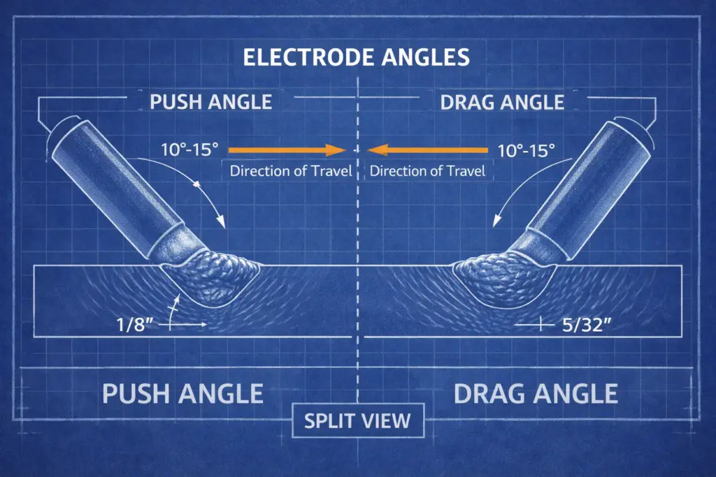
Travel Angle: Push (Forehand) versus Drag (Backhand)
| Technique | Electrode Direction | Travel Angle | Penetration | Best Used For |
|---|---|---|---|---|
| Push (Forehand) | Points in direction of travel | 5–15° push | Lower | Thin sheet, root passes with backing, MIG aluminium |
| Drag (Backhand) | Points opposite to travel | 5–15° drag | Higher | Thicker sections, SMAW, deep groove penetration |
| Perpendicular (Neutral) | 90° to workpiece | 0° | Intermediate | Flat fillet welds, general purpose |
Shielding Gas: Composition and Flow Rate
Shielding gas protects the molten weld pool and solidifying weld metal from atmospheric oxygen, nitrogen, and moisture that would cause porosity, oxidation, and nitrogen pick-up. Gas composition also directly influences arc stability, transfer mode, bead profile, and spatter level. For TIG (GTAW) and MIG (GMAW) processes, shielding gas selection is a critical process variable captured on the WPS.
| Gas / Blend | Typical Application | Arc Character | Penetration Profile | Spatter |
|---|---|---|---|---|
| 100% CO2 | GMAW mild steel (economical) | Rough, reactive | Deep, finger-type | High |
| 75% Ar / 25% CO2 (C25) | GMAW mild steel — most common blend | Smooth, stable | Intermediate | Moderate |
| 90% Ar / 10% CO2 | GMAW thin sheet, light structural | Very smooth | Slightly less than C25 | Low |
| 100% Ar | GTAW all metals; GMAW Al, Cu, Ni alloys | Very stable | Shallow, wide | Very low |
| Ar + 2–5% H2 | GTAW austenitic SS, Ni alloys | Hotter arc | Deeper | Low |
| He / Ar-He blends | GTAW non-ferrous, high deposition TIG | Hotter, high voltage | Deep | Low |
Preheat and Interpass Temperature
Preheat is the application of heat to the base metal before welding begins. Interpass temperature is the temperature of the weld region at the time the next pass is deposited. Both are specified on the WPS and enforced during production welding by inspection personnel. Failure to comply with preheat requirements is one of the most common causes of hydrogen-induced cracking (cold cracking) in carbon and low-alloy steels.
Why Preheat Is Required
- Reduces cooling rate: Slower cooling prevents hard martensitic microstructures from forming in the HAZ of hardenable steels.
- Reduces hydrogen cracking risk: Slower cooling allows hydrogen to diffuse out of the weld before the microstructure traps it at stress concentration points.
- Reduces thermal shock: On thick sections and cast iron, preheat prevents the steep temperature gradient between the weld zone and cold base metal from causing cracking.
- Improves fusion: A warm base metal slows initial solidification and improves flow of the weld pool into the joint root.
The minimum preheat temperature is determined by the material’s carbon equivalent (CE), material thickness, and the hydrogen content of the welding consumable. ASME D1.1 Annex I and BS EN ISO 10511 provide carbon equivalent formulas and minimum preheat temperature charts. For critical materials such as P91, preheat is typically 200°C minimum.
| Material | Min. Preheat (°C) | Max. Interpass (°C) | Notes |
|---|---|---|---|
| Mild steel <20 mm (CE <0.45) | None (ambient) | 250 | Low-hydrogen consumables recommended above 25 mm |
| Carbon-manganese steel 20–50 mm | 50–100 | 250 | Depends on CE; use CE formula |
| Low-alloy steel (P-No. 3, 4) | 100–175 | 250–300 | Higher preheat for SMAW with basic electrodes |
| P91 / Grade 91 | 200 | 300 | PWHT mandatory; strict interpass control to prevent delta ferrite |
| Austenitic stainless steel | None (ambient) | 150 | Low interpass essential to prevent sensitisation / weld decay |
| Duplex stainless steel | None (ambient, >10°C) | 150–200 | Excess heat input risks sigma phase precipitation |
| Cast iron | 150–400 | 350 | Slow cooling post-weld essential; butter layer often required |
Wire Feed Speed and Electrode Extension (Stick-Out)
Wire Feed Speed
In GMAW and FCAW, wire feed speed (WFS) in mm/min or in/min is the primary parameter controlling deposition rate and, in combination with voltage, arc current. On constant-voltage (CV) power sources, increasing WFS automatically draws more current from the power source to maintain arc length — this is the self-regulating arc behaviour fundamental to MIG welding. Use the MIG welding settings calculator to determine optimal WFS for your application.
Electrode Extension (Stick-Out)
Electrode extension, also known as contact-tip-to-work distance (CTWD), is the length of wire between the contact tip exit and the arc. Resistance in this length of wire (I²R heating) adds to the total energy applied to the wire. Longer stick-out increases this resistive preheating, raises the effective deposition rate, and reduces the current drawn from the power source (because the self-regulation mechanism compensates). The effect is used deliberately in FCAW with extended stick-out to preheat the flux core and improve slag chemistry, but in solid wire MIG it should be kept to the recommended range to avoid arc instability.
| Process / Transfer Mode | Recommended Stick-Out | Effect of Excessive Stick-Out |
|---|---|---|
| GMAW — Short Circuit Transfer | 10–13 mm (3/8–1/2 in) | Arc instability, porosity, irregular bead |
| GMAW — Spray Transfer | 15–19 mm (5/8–3/4 in) | Reduced penetration, burn-back into tip |
| FCAW-G (Gas Shielded) | 16–22 mm (5/8–7/8 in) | Inadequate gas shielding, porosity |
| FCAW-S (Self-Shielded) | 19–38 mm (3/4–1.5 in) | Slag coverage problems, undercut |
| GTAW (TIG) | Tungsten protrusion: 3–6 mm | Arc wander, tungsten contamination |
Process-Specific Parameter Considerations
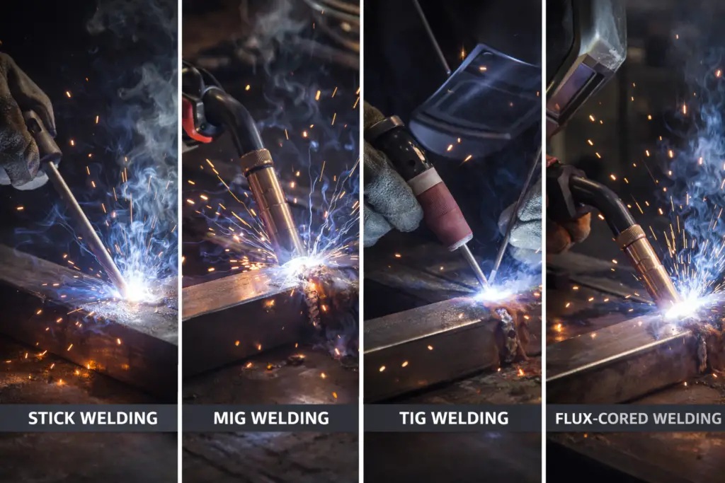
SMAW (Stick Welding)
Stick welding offers the fewest independently adjustable parameters — primarily current and polarity. Arc length management is the critical skill-dependent variable, as the welder manually maintains electrode gap throughout the pass. As the electrode shortens during welding, the welder must continuously advance it to maintain arc length, or the arc will extinguish. The electrode classification (e.g., E7018, E6010) dictates the required polarity, current type, and usable current range. For a complete guide, see the SMAW welding process guide.
GMAW (MIG/MAG Welding)
MIG welding provides the most independently controllable parameters: voltage, wire feed speed, shielding gas, travel speed, and stick-out. The interaction between voltage and WFS determines transfer mode. Modern synergic MIG machines store optimised voltage-WFS relationships for each wire type and diameter, allowing single-knob control for less experienced operators — though this can limit fine-tuning. For detailed setup guidance, use the MIG settings calculator on WeldFabWorld.
GTAW (TIG Welding)
TIG welding provides the finest possible parameter control: current (often via a foot pedal), tungsten geometry, shielding gas, filler rod addition rate, arc length, and travel speed are all independently controlled. Pulse TIG alternates between a high peak current and a lower background current, reducing average heat input while maintaining adequate penetration — ideal for thin materials, stainless steel root passes, and out-of-position welding. Use the TIG settings calculator to determine starting parameters for your application. See also the full GTAW process guide.
FCAW (Flux-Cored Arc Welding)
Flux-cored welding combines high deposition rates with good positional capability. It typically requires higher voltage than solid wire MIG at similar currents, producing a more fluid weld pool governed by the flux-slag system. Self-shielded FCAW (FCAW-S) eliminates shielding gas entirely, making it the preferred option for site welding in wind or tight spaces, but it requires strict attention to stick-out, polarity (usually DCEN), and travel speed to ensure adequate flux coverage and sound weld metal.
SAW (Submerged Arc Welding)
Submerged arc welding uses the highest currents of any common arc process (300–2000+ A) and delivers very high deposition rates with excellent penetration. Because the arc is submerged beneath a layer of flux, parameter interaction is complex — flux basicity, wire diameter, current type, and polarity all affect bead profile. SAW has k = 1.00 in the heat input calculation, reflecting its near-total thermal efficiency. Travel speed is typically tightly controlled by machine drive systems, making SAW the most reproducible arc process for heat input management.
Common Weld Defects Caused by Incorrect Parameters
| Defect | Parameter Cause | Corrective Action | Severity |
|---|---|---|---|
| Porosity | Insufficient gas flow, contaminated base metal, excessive voltage, too-high travel speed | Increase gas flow, clean surfaces, reduce voltage, reduce travel speed | Rejectable |
| Undercut | Excessive current, too-high voltage, incorrect electrode angle, excessive travel speed | Reduce current/voltage, correct angle, reduce travel speed | Conditional |
| Lack of fusion | Insufficient current, excessive travel speed, incorrect electrode angle | Increase current, slow down, correct angle to direct arc at fusion face | Rejectable |
| Excessive spatter | High current, high or low voltage (outside transfer window), wrong polarity, contamination | Adjust voltage to match transfer mode, verify polarity, clean surfaces | Cosmetic / compliance issue |
| Burn-through | Excessive current, slow travel speed, small root opening | Reduce current, increase travel speed, verify joint fit-up | Rejectable |
| Hot cracking | Excessive heat input, high sulphur content, concave bead shape (high voltage + high current) | Reduce heat input, select low-sulphur consumables, increase crown height | Rejectable |
| Cold cracking (HAC) | Insufficient preheat, low-hydrogen procedure not followed, excessive heat input (via rapid hardening) | Apply correct preheat per CE, use low-hydrogen consumables, bake electrodes | Rejectable |
Material-Specific Parameter Guidance
Mild and Carbon-Manganese Steel
Mild steel accepts the widest parameter range of any structural metal and is the most forgiving material for parameter optimisation. Use DCEP polarity for SMAW and GMAW. Heat input limits above 3.5 kJ/mm (88.9 kJ/in) should be treated with caution for structural work, as higher heat input can reduce HAZ toughness and increase distortion.
Stainless Steel
Austenitic grades (304, 316, 321, 347) require 10–15% lower heat input than equivalent-thickness mild steel to minimise time in the sensitisation temperature range (425–875°C) and prevent weld decay. Maximum interpass temperature of 150°C must be strictly maintained. Use DCEN for GTAW, DCEP for GMAW. For sour service applications, refer to sour service welding requirements.
Aluminium
Aluminium has approximately four times the thermal conductivity of steel, requiring higher current for equivalent thickness. It must be welded with 100% Argon shielding. Surface oxide must be removed mechanically or chemically immediately before welding — even a few minutes of re-oxidation significantly impairs fusion. AC TIG (with high-frequency start) provides the cathodic cleaning essential for fusion of oxides. GMAW of aluminium uses DCEP and spray transfer with an Argon shield.
Duplex and Superduplex Stainless Steels
Duplex stainless steels require heat input to be kept within a tightly defined window — typically 0.5 to 2.5 kJ/mm depending on grade. Too low heat input promotes excessive ferrite (poor toughness, reduced corrosion resistance); too high promotes sigma phase precipitation at grain boundaries. Interpass temperature is limited to 150°C maximum. The PREN of the weld metal should meet the parent specification — use the PREN calculator to verify.
Advanced Parameter Control Techniques
Pulse Welding
Pulse MIG and pulse TIG alternate between a high peak current (for penetration) and a lower background current (for cooling). This reduces average heat input while maintaining the ability to achieve spray-type metal transfer at lower mean currents. Pulse MIG is particularly effective for thin stainless sheet and aluminium. Modern pulse TIG machines allow independent control of peak current, background current, pulse frequency (Hz), and duty cycle.
Synergic Control
Synergic MIG machines store pre-programmed wire-type and diameter-specific parameter curves. When the operator adjusts wire feed speed, the machine automatically adjusts voltage to maintain the optimised arc characteristic. This simplifies setup but limits the fine-tuning available to an experienced operator working at the edge of the parameter window.
Waveform Control (AC TIG)
Advanced inverter TIG machines allow shaping of the AC waveform for aluminium welding. Increasing the percentage of electrode-negative (DCEN) half-cycle increases penetration at the expense of cleaning action; increasing electrode-positive (DCEP) time improves cleaning of thick oxide but concentrates more heat in the tungsten, requiring a larger-diameter tungsten to prevent balling. Frequency adjustment (20–200 Hz) controls arc focus: higher frequency produces a narrower, more focused arc.
Recommended Reference Books
The following titles are widely used by welding engineers, CWI candidates, and fabrication professionals studying welding parameters and process control.
Frequently Asked Questions
How do I calculate heat input in welding?
What happens if welding current is too high?
What is the correct arc voltage for SMAW stick welding?
What is the difference between DCEP and DCEN polarity in welding?
Why is interpass temperature control important in multi-pass welding?
What shielding gas should I use for MIG welding mild steel?
How does travel speed affect weld quality?
What is stick-out (electrode extension) and how does it affect MIG welding?
References
- American Welding Society. (2020). AWS D1.1/D1.1M: Structural Welding Code — Steel.
- American Society of Mechanical Engineers. (2021). ASME BPVC Section IX: Welding, Brazing, and Fusing Qualifications.
- American Welding Society. (2001). Welding Handbook, Volume 1: Welding Science and Technology (9th ed.).
- Lincoln Electric Company. The Procedure Handbook of Arc Welding (14th ed.).
- Messler, R.W. (2004). Principles of Welding: Processes, Physics, Chemistry, and Metallurgy. Wiley-VCH.
- Kou, S. (2003). Welding Metallurgy (2nd ed.). Wiley-Interscience.
- International Institute of Welding. (2012). IIW Doc. IX-2303-12: Thermal Efficiency Factors in Heat Input Calculation.