Duty Cycle in Welding: The Complete Guide with Calculator, Examples and Standards
Duty cycle in welding is the single most important specification on any welding power source datasheet — yet it is routinely misunderstood or ignored by welders at every level of experience. Whether you are selecting a new machine for a production shop, troubleshooting unexpected shutdowns during a fabrication run, or studying for a certification examination, a solid grasp of duty cycle will directly affect your efficiency, your weld quality, and the service life of your equipment.
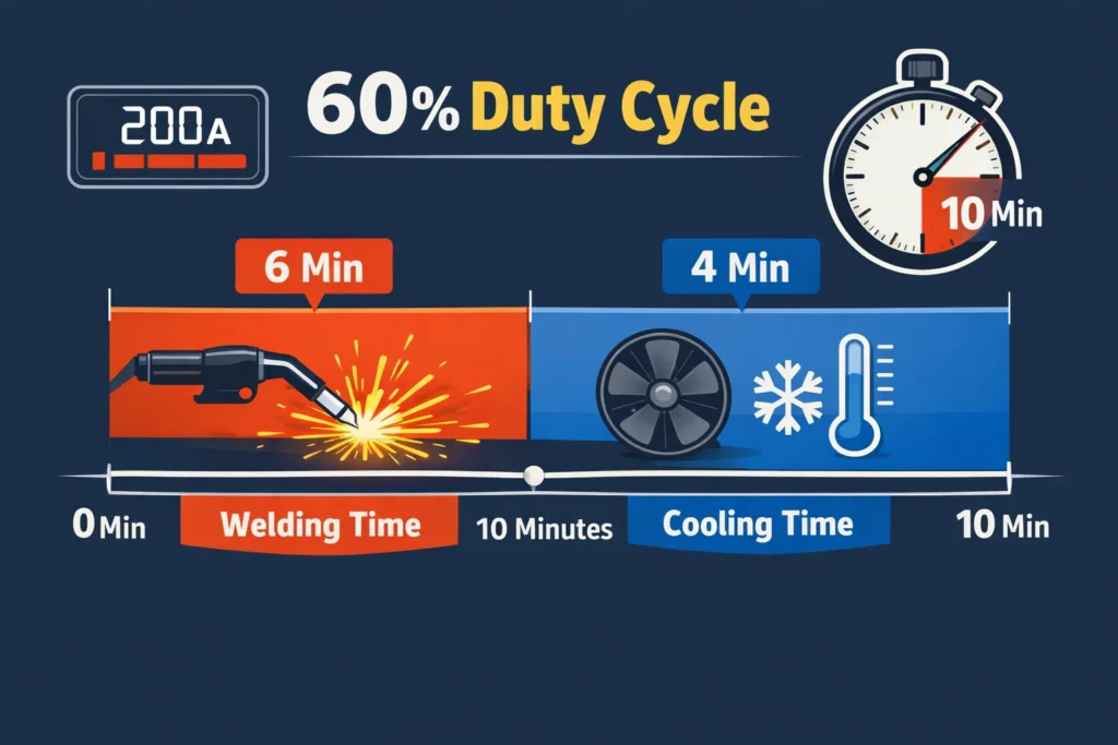
In simple terms, duty cycle tells you how long a welding machine can maintain its rated output current before the internal components reach their thermal limit and require a cooling period. It is always expressed as a percentage of a standard time window — almost universally 10 minutes under IEC/EN 60974-1. A machine rated at 60% duty cycle at 200 A can weld continuously for 6 minutes, after which it must be allowed to cool for at least 4 minutes before the next welding arc can be struck safely.
This guide covers the full picture: the formal definition, the derivation of the duty cycle formula, a free interactive calculator, the influence of ambient temperature and amperage on real-world performance, relevant standards including EN60974-1, machine selection guidance by application type, and a worked set of examples showing exactly how to apply the formula in engineering practice.
Duty Cycle Calculator
What Is Duty Cycle in Welding?
Duty cycle is defined as the ratio of the arc-on (welding) time to the total observation period, expressed as a percentage. In the welding industry, the observation period is standardised at 10 minutes under IEC 60974-1 and its European adoption EN60974-1. This 10-minute window is not arbitrary — it represents a thermal equilibrium interval for the internal power electronics under continuous cyclic loading.
Modern inverter-based welding machines use IGBT (Insulated Gate Bipolar Transistor) modules as their primary switching elements. These components are extraordinarily efficient but generate concentrated heat at high switching frequencies. When the thermal junction temperature of an IGBT approaches its maximum rated value (typically 150–175°C), the machine’s onboard thermal management system trips a protection relay, cutting arc output. This is the thermal overload event that welders experience as an unexpected shutdown mid-weld.
How Duty Cycle Is Expressed on a Nameplate
Manufacturers always quote duty cycle alongside the specific amperage at which it was measured, because the two values are inseparable. A nameplate might show any of the following:
- 60% @ 200 A — the machine can weld for 6 minutes continuously at 200 A
- 40% @ 250 A — at higher current, the machine can only sustain 4 minutes before cooling is required
- 100% @ 150 A — at a reduced output current, the machine generates so little heat that it can run indefinitely
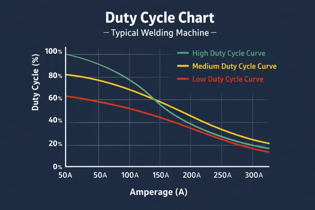
When a machine is operated at an amperage lower than the rated current, the duty cycle improves. When operated above the rated current (if the machine permits manual override), duty cycle degrades rapidly. The relationship between current and duty cycle follows the square-law approximation discussed in the formula section below.
The Duty Cycle Formula — Derivation and Application
The fundamental formula for duty cycle is straightforward:
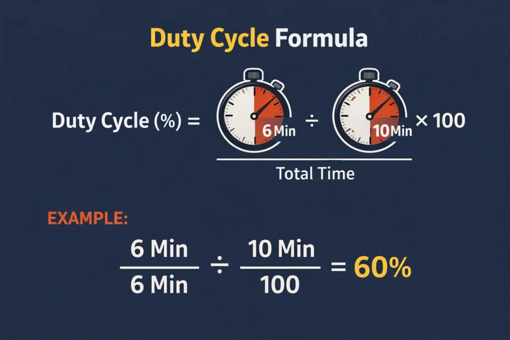
Formula: DC (%) = (t_on / T) × 100
Where: DC = duty cycle in percent
t_on = arc-on (welding) time in minutes
T = total observation period (standard: 10 minutes per EN60974-1)
Worked Example 1 — Finding Duty Cycle
Given: Welding time = 7 min, Rest time = 3 min, Total period = 10 min
Step 1: DC = (7 / 10) × 100
Result: DC = 70%
Worked Example 2 — Finding Arc-On Time from Duty Cycle
Given: Machine rated at 40% duty cycle. Total period = 10 min.
Step 1: t_on = (DC / 100) × T = (40 / 100) × 10
Result: t_on = 4 minutes welding, 6 minutes cooling
Converting Duty Cycle Between Amperage Levels
Since heat dissipation is proportional to I²R (power = current squared times resistance), the duty cycle at a new amperage level can be approximated using:
Formula: DC2 = (I1² × DC1) / I2²
Where: I1 = original current (A), DC1 = duty cycle at I1 (as decimal)
I2 = new current (A), DC2 = duty cycle at I2
Example: Rated 60% @ 200 A. What is DC at 250 A?
Step 1: DC2 = (200² × 0.60) / 250²
Step 2: DC2 = (40,000 × 0.60) / 62,500 = 24,000 / 62,500
Result: DC2 = 0.384 = 38.4% at 250 A
Note: This formula is an approximation. Actual performance depends on cooling system design.
Duty Cycle Standards — EN60974-1 and IEC 60974-1
The authoritative international standard governing welding machine duty cycle testing is IEC 60974-1 (Arc Welding Equipment — Part 1: Welding Power Sources), adopted in Europe as EN60974-1. This standard specifies the exact test conditions under which a manufacturer must measure and report duty cycle.
- Observation period: 10 minutes
- Ambient temperature: 40°C (standard test environment)
- The machine must be operated at its rated output current for the stated duty cycle duration, then the arc is extinguished and the machine cools for the remainder of the 10 minutes
- The machine must not trip its thermal overload protection during the rated arc-on period
A critical compliance issue is that some budget welding machine manufacturers do not test to EN60974-1 conditions. They may use a shorter observation period (e.g. 5 minutes instead of 10), a cooler ambient temperature, or an intermittent cycle that inflates the apparent duty cycle rating. Always look for explicit EN60974-1 or IEC 60974-1 compliance markings on the machine datasheet before accepting duty cycle figures at face value.
Factors That Affect Welding Machine Duty Cycle
Duty cycle is not a fixed property — it is a thermally governed variable that shifts with operating conditions. Understanding the factors below allows you to predict real-world performance and plan your welding sequences accordingly.
1. Output Current (Amperage)
This is the dominant factor. Because heat generation inside the machine is proportional to I²R, a modest increase in current causes a disproportionately large increase in internal heating. At twice the current, the machine generates four times the heat per unit time. The square-law approximation for converting duty cycle between amperage levels (covered in the formula section) quantifies this relationship. See the MIG welding settings calculator for guidance on selecting the correct amperage for your process.
2. Ambient Temperature
EN60974-1 rates machines at 40°C ambient. In a workshop during summer or in a hot climate, ambient temperatures can reach 40–50°C, reducing the machine’s thermal headroom and cutting the effective duty cycle. In cold environments (<20°C), the machine’s cooling efficiency improves and duty cycle may modestly exceed its rated value. For work in hot environments, select a machine rated at 60°C ambient if the manufacturer offers that specification.
3. Cooling System Design
Welding machines use two primary cooling approaches: forced air cooling (a cooling fan driving air across heatsinks) and natural convection (passive heatsink design, common in small hobby units). Forced air cooling provides substantially better duty cycles at high currents. Industrial machines with large heat sinks and high-flow fans routinely achieve 80–100% duty cycle ratings. Ensure the machine’s cooling vents are never blocked and that the fan operates correctly — a failed fan will dramatically reduce effective duty cycle.
4. Machine Age and Maintenance Condition
Internal components degrade over time. Electrolytic capacitors lose capacitance and increase internal resistance, generating more heat for the same output. Thermal grease between IGBT modules and heatsinks dries and cracks, increasing thermal resistance. Accumulated dust and debris inside the enclosure insulates heat-generating components. A well-maintained machine consistently delivers its rated duty cycle; a neglected one can fall significantly short.
5. Duty Factor of the Weld Sequence
In production welding, the actual duty factor of a welding sequence includes not just arc-on time but the complete work cycle: positioning the workpiece, tack welding, grinding, cleaning, interpass temperature checks, and fit-up adjustments. The true arc-on fraction within a full work cycle is often 30–50% even for experienced welders. When planning production capacity, use the real arc-on fraction, not just the machine’s rated duty cycle.
Real-World Duty Cycle Examples
The table below shows how duty cycle translates into practical arc-on and cooling times across a range of machine ratings. Use this as a quick reference when scheduling weld sequences or evaluating machine specifications against your project’s demands.
| Machine Rating | Arc-On Time | Cooling Time | Typical Application | Suitability |
|---|---|---|---|---|
| 20% @ 300 A | 2 min | 8 min | Light hobby / repair welding | Limited |
| 40% @ 250 A | 4 min | 6 min | General fabrication, intermittent welding | Moderate |
| 60% @ 200 A | 6 min | 4 min | Mid-volume fabrication, structural tacking | Good |
| 80% @ 200 A | 8 min | 2 min | Production fabrication, pipe welding | High |
| 100% @ 200 A | 10 min | 0 min | Continuous industrial / SAW production | Industrial |
| 100% @ 350 A | 10 min | 0 min | Heavy structural, pressure vessel fabrication | Industrial |
Duty Cycle and Welding Productivity
From a production engineering perspective, duty cycle directly determines the maximum achievable deposition rate per hour. A welder with a 60% duty cycle machine can only deposit metal during 60% of total arc time available. The remaining 40% is mandatory cooling time. For a six-hour shift with continuous welding demand, this means only 3.6 hours of actual arc-on time — a significant constraint on throughput.
Machines with higher duty cycles at the required amperage command premium prices, but the productivity gains often justify the investment in production environments. A machine costing 30% more but delivering 80% vs 60% duty cycle at the same current effectively increases productive welding time per shift by 33% — a straightforward return-on-investment calculation for any fabrication manager.
Comparing Duty Cycle Across Welding Processes
Different welding processes have inherently different arc-on fractions due to their operating characteristics. Process selection therefore interacts with machine duty cycle in planning weld schedules:
| Welding Process | Typical Arc-On Fraction | Machine DC Requirement | Notes |
|---|---|---|---|
| SMAW (Stick) | 25–40% | 40–60% @ rated A | Electrode changes reduce arc-on fraction |
| GMAW (MIG) | 50–70% | 60–80% @ rated A | Continuous wire feed increases arc-on time |
| GTAW (TIG) | 30–50% | 60% @ rated A | Filler dipping and repositioning reduce arc-on |
| SAW (Submerged Arc) | 70–100% | 100% @ rated A | Automated process; near-continuous arc required |
| FCAW (Flux-Cored) | 55–75% | 70–80% @ rated A | Similar to GMAW but with slag removal downtime |
Choosing the Right Welding Machine Based on Duty Cycle
Machine selection based on duty cycle requires matching the machine’s rated performance at the anticipated operating amperage to the actual arc-on demands of the job. The following decision framework applies across all welding processes:
Step 1: Determine Your Required Amperage
Use established process parameters for your base material, thickness, and process. The MIG settings calculator and TIG settings calculator on WeldFabWorld provide starting point parameters. Material composition also influences the appropriate current range — for high-alloy steels such as P91 Grade 91, preheat and interpass temperature requirements further constrain the operating window.
Step 2: Estimate Your Required Arc-On Fraction
For your specific job type, estimate the realistic arc-on fraction as a percentage of total shift time, accounting for tacking, grinding, repositioning, inspection, and consumable changes. This fraction represents the effective duty cycle your machine must sustain.
Step 3: Apply a Safety Margin
Select a machine whose rated duty cycle at the required amperage exceeds your estimated arc-on fraction by at least 10–15 percentage points. This margin accommodates ambient temperature variation, machine aging, and unexpected extended weld runs.
- Home / hobby / farm repair: 20–40% duty cycle is usually adequate. Low arc-on fraction, intermittent use.
- General fabrication workshop: 40–60% duty cycle at rated amperage. Balanced cost and performance.
- Structural steel fabrication: 60–80% duty cycle. Long continuous welds, high arc-on demand.
- Pressure vessel / pipeline production: 80–100% duty cycle. Stringent code compliance, near-continuous welding required.
- Automated / robotic welding: 100% duty cycle mandatory. Robots do not take cooling breaks.
What Happens When You Exceed the Duty Cycle?
Exceeding duty cycle is not merely an inconvenience — it has a direct impact on machine longevity and, in machines with inadequate protection, can cause component failure. The consequences cascade in severity as follows:
Immediate Response: Thermal Overload Trip
All EN60974-1-compliant machines incorporate a thermostat or thermistor monitoring IGBT junction temperature. When the temperature threshold is exceeded, the controller cuts arc output and illuminates a thermal overload indicator. The machine typically recovers within 3–10 minutes depending on ambient conditions and the severity of the overrun. During this time, no welding is possible.
Medium-Term: Accelerated Component Degradation
Each thermal cycle stresses the solder joints on the power electronics PCB, the wire bonds on IGBT chips, and the terminals on high-current connections. Progressive thermal cycling causes micro-cracking in solder joints, increasing resistance and generating more heat in subsequent cycles — a self-reinforcing degradation mechanism. IGBT modules typically carry a rated junction temperature cycle count; operation above rated duty cycle consumes this life budget prematurely.
Long-Term: Capacitor Failure
Electrolytic capacitors in the DC bus of inverter welding machines are particularly sensitive to temperature. Elevated temperature approximately halves capacitor life for every 10°C increase above rated temperature. Regularly exceeding duty cycle in a hot environment can reduce a capacitor’s expected service life from 10 years to 2–3 years, resulting in arc instability, voltage ripple, and eventual machine failure.
Practical Engineering Tips for Managing Duty Cycle
Maintain Cooling Vents and Fans
Blow out internal dust deposits with compressed air every 3–6 months. A blocked fan or dust-clogged heatsink can reduce effective duty cycle by 20–30%. Ensure a minimum 150 mm clearance around all cooling vent openings.
Plan Your Weld Sequence Around Duty Cycle
For a machine with 60% duty cycle at your operating current, structure your welding sequence with natural breaks: weld one section, reposition or prepare the next joint during the mandatory cooling window, then weld again. Integrated into good practice, the cooling time is never wasted — it is used for preparation, inspection, and interpass temperature verification using a temperature check method.
Derate in Hot Environments
At 50°C ambient, apply a derating factor of approximately 0.85 to the nameplate duty cycle. At 60°C ambient, apply 0.70. If extended high-ambient work is expected, select a machine with a higher base rating than nominally required.
Use Preheat Periods Efficiently
For welding materials requiring preheat (such as P91 chromium-molybdenum steel), the preheat and interpass temperature soaking periods serve double duty as machine cooling intervals. Plan preheat and interpass checks to coincide with the mandatory cooling window of your duty cycle.
Consider Water-Cooled Torches for High-Duty-Cycle GTAW
For TIG welding at high currents with extended arc-on times, a water-cooled torch dramatically reduces heat conducted back to the machine and the welder’s hand, allowing more sustained operation closer to the machine’s rated duty cycle ceiling.
Recommended Resources for Welding Engineers
Disclosure: WeldFabWorld participates in the Amazon Associates programme (StoreID: neha0fe8-21). If you purchase through these links, we may earn a small commission at no extra cost to you. This helps support free technical content on this site.
Frequently Asked Questions — Duty Cycle in Welding
What is duty cycle in welding?
How is welding duty cycle calculated?
Why does duty cycle decrease at higher amperage?
What is the standard period used for duty cycle testing?
What duty cycle do I need for structural fabrication?
What happens if I exceed the duty cycle of my welder?
Does ambient temperature affect welding duty cycle?
How do I convert duty cycle between different amperage levels?
Summary
Duty cycle is one of the most consequential specifications on any welding power source — it determines how long you can sustain an arc before a mandatory cooling pause, and it changes with every variation in output current and ambient temperature. The key takeaways from this guide are:
- Duty cycle = (Arc-On Time / 10 min) × 100, per EN60974-1
- Always read the amperage rating alongside the duty cycle percentage — they are inseparable
- Duty cycle decreases with increasing current following the I² square-law relationship
- Budget machines tested to non-standard conditions may overstate their duty cycle ratings
- Select a machine with at least 10–15 percentage points of headroom above your estimated arc-on fraction
- Cooling vent maintenance, ambient temperature management, and proper sequencing are all tools for getting the most from your machine’s rated duty cycle
For further reading on welding machine parameters and process settings, see the MIG welding settings calculator, the TIG welding settings calculator, and the comprehensive SMAW welding guide on WeldFabWorld.