Ultrasonic Welding of Injection-Moulded Components
Component Design and Weld Parameters Explained
Ultrasonic welding is one of the most efficient and widely used techniques for joining thermoplastic components, particularly in the automotive, electronics, medical device, and consumer product sectors. The process applies high-frequency mechanical vibrations — typically between 20 kHz and 40 kHz — to plastic parts held under pressure, generating localised heat at the joint interface that melts and fuses the material in a fraction of a second. Understanding the relationship between component design, material selection, and process parameters is essential for engineers who need to produce strong, consistent, and aesthetically clean welds at production volume.
This guide covers the full picture of ultrasonic welding as applied to injection-moulded thermoplastics: how the process works, the major joint design types (energy director, tongue-and-groove, and shear joint), the critical welding parameters and their effects, near-field vs. far-field considerations, and a practical design checklist. Whether you are designing parts from scratch or troubleshooting an existing production line, these principles will help you achieve reliable, repeatable results.
What Is Ultrasonic Welding of Plastics?
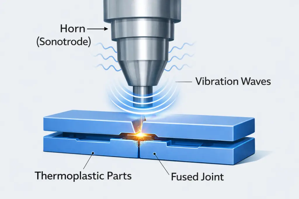
Ultrasonic welding is a solid-state thermoplastic joining process that uses high-frequency mechanical vibrations to generate localised frictional and viscoelastic heat at the part interface. A metal tool known as the horn (or sonotrode) is pressed against the upper component and vibrates at frequencies of 20 kHz, 30 kHz, or 40 kHz with amplitudes typically between 15 and 120 microns. The resulting oscillatory motion is transmitted through the part until it reaches the joint interface, where energy concentration and intermolecular friction raise the temperature above the plastic’s melting point. The melt flows and consolidates under applied pressure, then solidifies during the hold phase to produce the finished weld.
The entire cycle — from trigger to weld complete — typically takes between 0.1 and 3.0 seconds, making ultrasonic welding one of the fastest thermoplastic joining methods available. Unlike adhesive bonding, it requires no cure time; unlike mechanical fastening, it requires no additional components; and unlike hot-plate welding, the horn does not require heating or cooling. These characteristics make it the dominant joining method for high-volume injection-moulded plastic assemblies worldwide.
Why Ultrasonic Welding Is Preferred
- No adhesives, solvents, or fasteners required — cost reduction and part weight saving
- Very short cycle times (typically 0.5–2.5 s including hold time) — high throughput
- Clean, dry, and repeatable process compatible with automation
- Strong, structural welds with good cosmetic finish when properly designed
- Hermetic sealing capability with correct joint geometry
- No post-processing or secondary operations required in most applications
Importance of Component Design in Ultrasonic Welding
The single most important factor in achieving a reliable ultrasonic weld is component design. Even the most capable welding machine cannot produce a satisfactory result if the part geometry is fundamentally wrong. Component geometry controls three things: where heat is generated, how molten plastic flows within the joint, and what the final weld strength and appearance will be.
Poor part design produces characteristic failure modes: insufficient melting where the energy is too diffuse, excessive flash where the melt has no containment, misaligned parts where the joint has no self-locating feature, or inconsistent weld depth from shot to shot. All of these can be prevented at the design stage at zero additional cost.

General Design Principles
- Uniform wall thickness near the joint ensures consistent vibration transmission and even heat generation
- Avoid abrupt thickness changes within 10 mm of the joint area — these create stress concentrations and uneven energy distribution
- Avoid large flat areas between the horn contact surface and the joint — these act as energy absorbers and reduce far-field welding efficiency
- Self-locating features (such as tongue-and-groove or alignment pins) are strongly recommended to ensure consistent part positioning shot to shot
- Radii at corners improve vibration transmission and reduce stress cracking during welding
Energy Director (Projection) Joint Design
The energy director is the most widely used joint design in ultrasonic welding of injection-moulded plastics. It consists of a small triangular ridge — the energy director — moulded onto one of the mating surfaces. When the horn applies vibration, this pointed ridge concentrates the ultrasonic energy at a single narrow line of contact, generating heat rapidly and efficiently. As the energy director melts, the molten plastic flows outward to fill the joint gap, and pressure consolidates the weld.
Energy director joints are relatively easy to mould, work well with amorphous thermoplastics, and produce clean welds with short cycle times. They are the default choice for structural bonds in parts such as appliance housings, consumer electronics enclosures, and packaging closures.
Energy Director Geometry by Plastic Type
| Plastic Classification | Common Materials | Recommended Profile | Typical Height | Notes |
|---|---|---|---|---|
| Amorphous | ABS, PC, PS, PMMA, SAN | Right-angle triangle (90° apex) | 0.3–0.5 mm | Broad melt range makes energy director highly effective; right-angle profile works well |
| Semi-crystalline | PP, Nylon (PA6/66), POM, HDPE | Equilateral triangle (60° apex) | 0.5–0.8 mm | Sharp melting transition requires more energy concentration; taller equilateral profile preferred |
| Filled grades | Glass-filled PP, carbon-filled PA | Equilateral, increased height | 0.6–1.0 mm | Fillers raise melt temperature and reduce flowability; higher energy director compensates |
Tongue and Groove Joint Design
The tongue-and-groove joint is a refinement of the energy director concept. One mating surface carries a projecting tongue with a small energy director at its tip; the other carries a matching groove. When assembled, the tongue sits inside the groove with a clearance fit before welding. The groove walls constrain the melt flow during welding, preventing visible flash on the outer surface while providing self-locating alignment between the two parts.
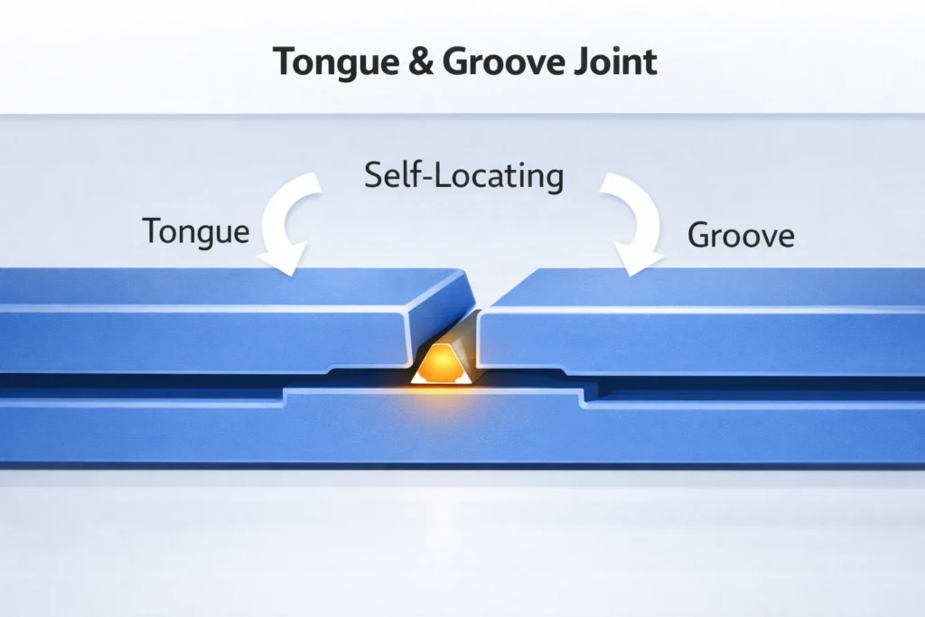
Advantages of Tongue and Groove
- Self-locating during assembly — reduces fixturing requirements
- Flash is hidden within the groove — improved cosmetic appearance on visible surfaces
- Controlled melt flow reduces the risk of flash contaminating internal components or sealing surfaces
- Good for moderate-strength requirements with clean exterior finish
Design Tolerances
The tongue should fit the groove with a clearance of 0.1–0.25 mm per side. Tighter fits make assembly difficult; looser fits allow part movement during welding and produce inconsistent results. Moulding tolerances for the tongue and groove features must be carefully controlled — typically ±0.05 mm or better for reliable performance.
Shear Joint Design — High-Strength and Hermetic Applications
The shear joint is the correct choice where maximum weld strength or hermetic sealing is required. Unlike energy director joints where melting occurs at the tip of a triangle, shear joints produce melting along vertical sidewalls as one part telescopes into another under vibration. The melt front progresses down the joint depth, producing a large, dense bond area with minimal porosity.
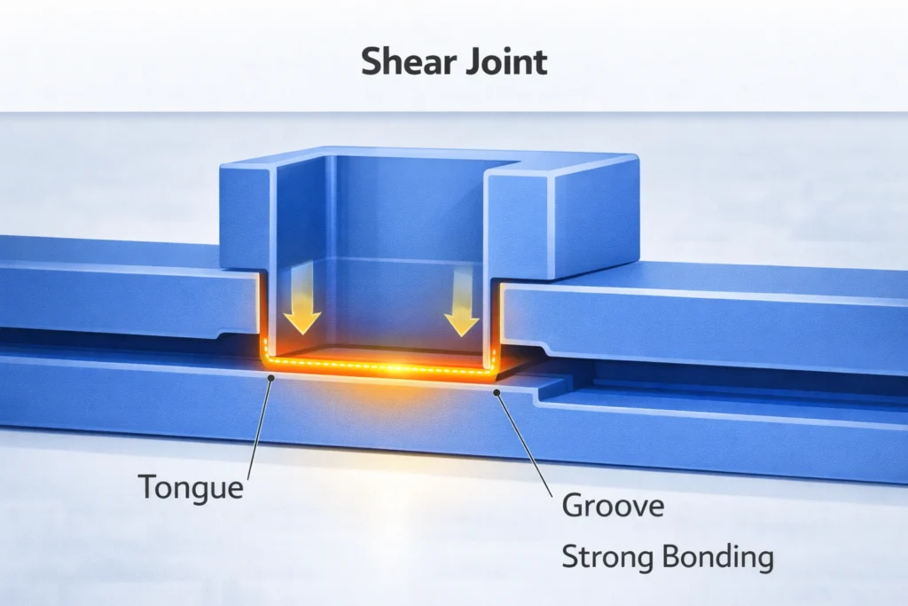
How Shear Joints Work
The inner part is slightly larger than the outer — a designed interference fit, typically 0.2–0.4 mm per side. Before welding, the parts are assembled with a press fit that initially contacts along the leading edge. When ultrasonic vibration is applied, the friction and viscoelastic heating at the interference zone causes progressive melting as the inner part slides downward. A step or ledge at the end of the joint controls the final weld depth and provides a reference stop.
Shear Joint Design Parameters
| Parameter | Typical Range | Notes |
|---|---|---|
| Interference per side | 0.2–0.4 mm | Lower end for large parts, upper end for small parts; must be consistent around entire joint |
| Joint depth | 1.25–1.5× wall thickness | Deeper joints produce stronger welds; minimum 1.5 mm regardless of wall thickness |
| Lead-in chamfer | 0.3–0.5 mm at 30–45° | Guides initial assembly and prevents gouging before vibration starts |
| Wall thickness balance | Inner wall ≥ outer wall | Outer wall should be thicker to prevent outward deflection under weld pressure |
Applications
- Medical fluid containers, blood glucose devices, IV connectors
- Automotive fluid reservoirs (washer fluid, coolant overflow tanks)
- Sealed electronic enclosures requiring IP-rated protection
- Aerosol and pressurised packaging
Near-Field vs Far-Field Ultrasonic Welding
The distance between the horn contact surface and the joint interface has a profound effect on energy delivery efficiency. This relationship defines whether a weld is classified as near-field or far-field, and it is one of the most important considerations in joint location during part design.
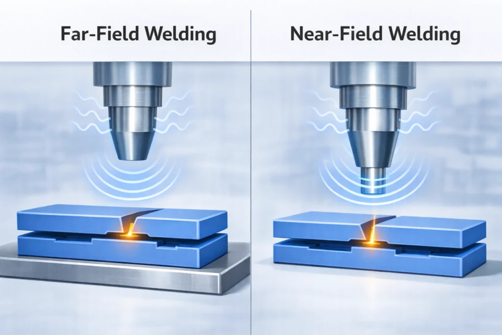
| Parameter | Near-Field (≤ 6 mm) | Far-Field (> 6 mm) |
|---|---|---|
| Energy transfer efficiency | High | Moderate to Low |
| Suitable material types | Amorphous and semi-crystalline | Primarily amorphous (ABS, PC, PS) |
| Amplitude requirement | Standard (15–60 µm) | Higher (50–120 µm) |
| Risk of surface marking by horn | Higher — use surface protection | Lower |
| Preferred for | High-strength and hermetic welds | Cosmetic or delicate assemblies |
Avoiding Sharp Corners — Use Radii
Sharp corners in the vicinity of the joint act as stress raisers and disrupt the smooth transmission of ultrasonic vibration through the part. At frequencies of 20–40 kHz, even small geometric discontinuities can cause localised resonance, heating in unintended locations, surface crazing, and in severe cases, fracture of the part wall before the joint has adequately melted. This is particularly important for brittle amorphous materials such as polycarbonate and PMMA.
Design best practice is to specify a minimum corner radius of 0.5 mm for internal corners and 1.0 mm for external corners in any region that will experience significant vibration amplitude during welding. At design transitions between thin and thick sections, the change should be gradual — no step change greater than 2:1 in wall thickness within 5 mm of the joint area. This applies to ribs, bosses, and gussets near the joint perimeter as well as to the main walls.
Key Ultrasonic Welding Parameters
Once the part design is finalised, process parameters determine whether the joint is correctly made. The four primary parameters — amplitude, trigger pressure, weld time (or weld energy), and hold time — interact with one another and with the material to define the outcome. Modern ultrasonic welding machines also offer energy and distance control modes, which are discussed below.
1. Amplitude
Amplitude is the peak-to-peak displacement of the horn face, typically expressed in micrometres (µm). It is the single most important parameter for controlling energy delivery to the joint. Higher amplitude generates more heat per unit time; lower amplitude produces slower, more controlled melting. The correct amplitude depends on material type, part stiffness, joint geometry, and the near-field or far-field condition.
| Material Type | Typical Amplitude Range | Notes |
|---|---|---|
| Amorphous (ABS, PC, PS, PMMA) | 15–35 µm | Broad softening range; lower amplitude is generally sufficient |
| Semi-crystalline (PP, PA, POM) | 40–90 µm | Sharp melt point requires higher amplitude to initiate melting quickly |
| Far-field amorphous | 40–70 µm | Additional amplitude needed to compensate for energy attenuation in part |
| Filled/reinforced grades | 50–120 µm | Fillers reduce damping and require higher amplitude; verify flash is controlled |
2. Trigger Pressure (Pre-Pressure)
Trigger pressure is the force applied to bring the parts into contact and hold them firmly before and during the initiation of vibration. It ensures consistent part seating in the fixture and controlled initial contact at the energy director tip. Trigger pressure that is too low allows parts to bounce or misalign before welding starts; pressure that is too high can cause premature mechanical damage at the contact tip before enough heat has been generated.
3. Weld Time, Energy, and Distance Control Modes
Modern ultrasonic welding machines offer three primary process control modes:
- Time mode: Vibration is applied for a fixed number of seconds. Simple but sensitive to variation in part dimensions and material shot-to-shot.
- Energy mode: Vibration continues until a target joule value has been delivered to the joint. More consistent than time mode across part-to-part variation.
- Distance/collapse mode: Vibration continues until the horn has traveled a set downward distance (the “collapse distance”). Most consistent for strength and hermetic seal applications because it directly controls melt volume and joint compression.
For production applications requiring dimensional consistency or hermetic sealing, distance mode is strongly preferred. Energy mode is a good intermediate choice for structural bond applications. Time mode is adequate for prototyping and early-stage development.
4. Hold Time
Hold time is the period after vibration stops during which the weld pressure is maintained. During this phase, the molten material at the joint interface solidifies under pressure. Adequate hold time is critical: if the pressure is released before the melt has fully solidified, the joint will relax and produce a weak, low-density bond. Typical hold times range from 0.1 to 1.0 seconds. Crystalline plastics and large-volume energy directors generally require longer hold times.
Materials Compatible with Ultrasonic Welding
Material compatibility is determined primarily by the thermoplastic’s viscoelastic damping characteristics — the ability of the molecular chains to convert mechanical vibration into heat. Amorphous thermoplastics generally weld more easily than semi-crystalline ones. Both categories of material must be compatible at the joint interface; dissimilar plastic welding is generally not possible unless the two materials have a common molecular base or are specifically formulated as compatible blends.
| Material | Type | Weldability | Preferred Joint Design |
|---|---|---|---|
| ABS | Amorphous | Excellent | Energy director or tongue-and-groove |
| Polycarbonate (PC) | Amorphous | Excellent | Energy director |
| Polystyrene (PS) | Amorphous | Excellent | Energy director |
| PMMA (Acrylic) | Amorphous | Good | Energy director — brittle; use lower amplitude |
| Polypropylene (PP) | Semi-crystalline | Moderate | Shear joint; near-field strongly preferred |
| Nylon / PA6, PA66 | Semi-crystalline | Moderate | Shear or shear-energy director hybrid; dry weld only |
| POM (Acetal) | Semi-crystalline | Moderate | Shear joint; very sharp melt transition requires careful parameter control |
| HDPE / LDPE | Semi-crystalline | Difficult | Near-field shear only; better alternatives often exist |
| PEEK, PPS, LCP | Semi-crystalline (high-temp) | Specialist | Shear joint; high-power 20 kHz equipment required |
Practical Ultrasonic Welding Design Checklist
Use this checklist before finalising a plastic part for ultrasonic welding:
- Correct joint design selected (energy director, tongue-and-groove, or shear) for application requirements
- Material compatibility confirmed — both parts are the same thermoplastic or known-compatible blends
- Energy director geometry matches plastic type (right-angle for amorphous, equilateral for semi-crystalline)
- Shear joint interference per side within 0.2–0.4 mm and consistent around full perimeter
- Wall thickness near joint is uniform; no abrupt changes within 10 mm of joint
- Corner radii applied at all internal corners (≥0.5 mm) and external corners (≥1.0 mm) near joint
- Self-locating features (groove, alignment ribs, or pins) included for consistent part positioning
- Joint is near-field (≤6 mm from horn) where possible; if far-field, confirm material is amorphous
- Flash trap or groove included for cosmetic surfaces
- Moulding tolerances for joint features specified at ±0.05 mm or tighter
Comparison with Other Thermoplastic Joining Processes
| Process | Cycle Time | Hermetic Seal | Part Size | Investment Cost | Best For |
|---|---|---|---|---|---|
| Ultrasonic Welding | <3 s | Yes (shear) | Small–medium | Medium | High-volume, small parts |
| Vibration Welding | 5–20 s | Yes | Medium–large | High | Large automotive parts, intake manifolds |
| Hot Plate Welding | 15–60 s | Yes | Any | Low–medium | Large flat joint areas; PP tanks |
| Laser Welding | 3–30 s | Yes | Small–medium | High | Zero-flash medical, transparent parts |
| Adhesive Bonding | Cure: minutes–hours | Possible | Any | Low | Dissimilar materials, complex geometry |
Frequently Asked Questions
What frequency is used in ultrasonic welding?
What is an energy director in ultrasonic welding?
What is the difference between near-field and far-field ultrasonic welding?
Which plastics can be ultrasonically welded?
What causes flash in ultrasonic welding?
What is hold time in ultrasonic welding and why is it important?
Can ultrasonic welding achieve hermetic seals?
How does wall thickness affect ultrasonic welding?
Recommended Reading
Deepen your knowledge of plastic welding, joining technology, and thermoplastic design with these recommended titles:
Disclosure: WeldFabWorld participates in the Amazon Associates programme (StoreID: neha0fe8-21). If you purchase through these links, we may earn a small commission at no extra cost to you. This helps support free technical content on this site.