Introduction
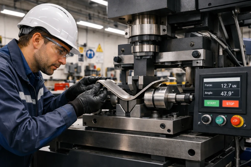
Bend testing represents one of the most practical and cost-effective methods for evaluating material ductility, weld integrity, and overall joint quality in metallic structures. This non-destructive to semi-destructive testing technique has become an industry standard across manufacturing, construction, aerospace, and energy sectors due to its simplicity, reliability, and immediate results.
Unlike complex mechanical testing methods that require expensive equipment and extensive specimen preparation, bend testing delivers critical insights into material behavior under plastic deformation with minimal investment. This guide explores the comprehensive principles, methodologies, applications, and best practices of bend testing to help quality assurance professionals, welding engineers, and materials scientists achieve optimal results.
Understanding Bend Testing Fundamentals
What is Bend Testing?
Bend testing is a qualitative mechanical test designed to assess the ductility and soundness of metallic materials by subjecting a coupon (test specimen) to controlled plastic deformation. The specimen is bent around a former or mandrel to a predetermined angle, typically 90°, 120°, or 180°, while the outer surface experiences tensile strain that reveals any internal defects, embrittlement, or discontinuities.
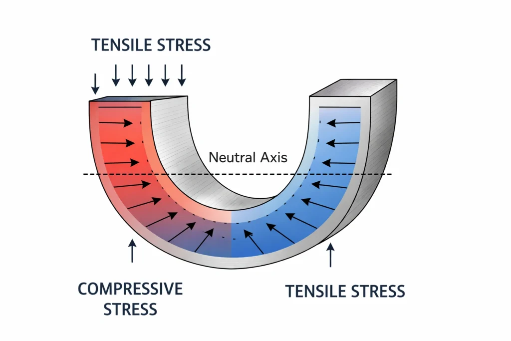
The beauty of this test lies in its fundamental principle: when a material is bent, the convex (outer) surface is placed under significant tensile stress while the concave (inner) surface experiences compressive stress. Any flaws, lack of fusion, porosity, or material weakness will manifest as cracks or failures on the tension face, making them immediately visible for evaluation.
Types of Bend Tests
Bend testing encompasses several variations, each suited to specific applications and material conditions:
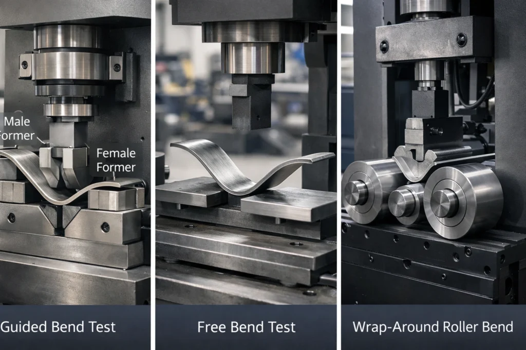
1. Guided Bend Test
The guided bend test is the most commonly specified method in welding standards and specifications. The specimen is wrapped around a precisely machined former (mandrel) of specified diameter, ensuring consistent and reproducible results. This controlled approach is mandatory in qualification procedures such as ASME IX, ISO 9606, and ISO 15614.
The former diameter is expressed as a multiple of the specimen thickness (t), such as 3t, 4t, or 8t, with the specific value determined by material properties, strength levels, and applicable standards.
2. Free Bend Test
In free bend testing, the specimen is bent without constraint from a former, allowing natural deformation. While this method requires less specialized equipment, it provides less control over bend radius and strain distribution, making it less suitable for qualification testing but useful for preliminary material evaluation.
3. Wrap-Around Bend Test
Similar to the guided bend test but utilizing a roller-based mechanism resembling a pipe bender, this method progressively wraps the specimen around the former. This technique is particularly advantageous for dissimilar metal joints or materials with significantly different strength levels, as it minimizes the “peaking” phenomenon where deformation concentrates in the weaker material.
Equipment and Test Apparatus
Standard Guided Bend Test Jig
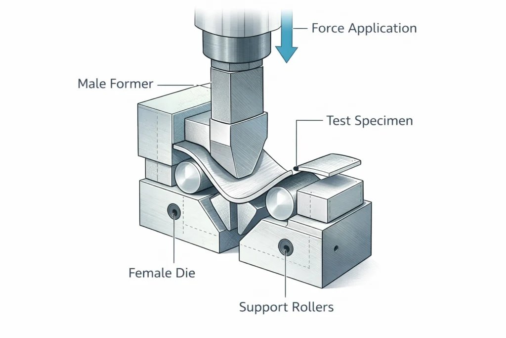
The most prevalent bend testing equipment consists of a male former (mandrel) and a female die with a curved recess. The specimen is placed between these components, and force is applied through a hydraulic press, manual screw mechanism, or lever system until the desired bend angle is achieved.
Key components include:
- Male former: A precisely machined cylindrical or semi-cylindrical mandrel with diameter specified by testing standards
- Female die: A matching curved recess that accommodates the bent specimen
- Support rollers: Allow smooth movement of the specimen during bending
- Force application system: Hydraulic, mechanical, or manual mechanism to apply bending force
- Angle measurement device: Protractors or digital angle indicators to verify bend angle
Wrap-Around Bend Test Machine
This specialized equipment operates on principles similar to pipe bending machinery. The specimen is clamped at one end while rollers progressively wrap it around a central former. This controlled progressive bending distributes strain more uniformly across the specimen, making it ideal for challenging material combinations.
Test Specimen Preparation
Specimen Dimensions and Orientation
Proper specimen preparation is critical to valid test results. Dimensions and orientation vary based on material thickness and the specific properties being evaluated:
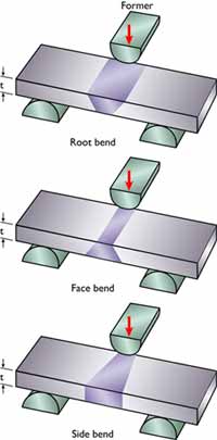
Transverse Specimens
These specimens are cut perpendicular to the welding direction and include:
- Face Bend: Weld face placed on the tension (outer) side to reveal surface defects, undercut, or cap-related discontinuities
- Root Bend: Weld root positioned on the tension side to detect lack of root penetration or fusion
- Side Bend: Full thickness specimen bent with the side in tension, excellent for detecting lack of sidewall fusion in thicker materials (typically >12mm)
Standard dimensions:
- Length: Sufficient to span the test jig with 10-25mm clearance each side
- Width: Typically the full weld width plus 5mm each side of parent metal
- Thickness: As-welded or machined to specified thickness
Longitudinal Specimens
Cut parallel to the welding direction, these specimens include the full weld width, both heat-affected zones (HAZ), and portions of each parent metal. They’re particularly useful for:
- Dissimilar metal welds
- Joints with significant strength mismatch between weld and parent metal
- Detecting transverse defects
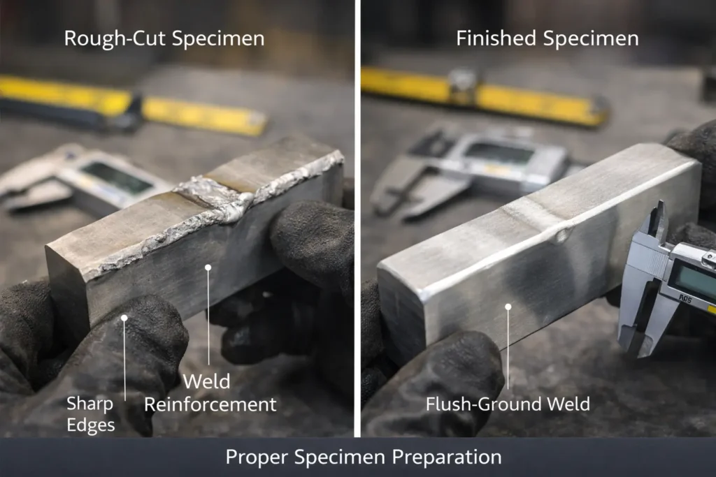
Surface Preparation Requirements
Specimen surfaces require careful preparation to prevent premature failure from stress concentrations unrelated to weld quality:
- Weld Surface Machining: Face and root reinforcement should be ground flush with parent metal surface to eliminate stress risers
- Edge Preparation: All edges must be rounded to a maximum radius of 3mm to prevent edge cracking
- HAZ Removal from Cut Edges: Any heat-affected zone from flame cutting or work-hardening from shearing must be removed by machining or grinding
- Surface Finish: Achieve a smooth finish free from tool marks, grinding marks, or other surface irregularities that could initiate cracking
Test Procedure and Methodology
Step-by-Step Testing Process
1. Pre-Test Inspection
- Verify specimen dimensions against specification requirements
- Confirm proper surface preparation
- Check for pre-existing surface defects
- Photograph specimen for documentation
2. Former Selection
Select the appropriate former diameter based on:
- Material specification requirements
- Material type and strength level
- Thickness of test specimen
- Applicable testing standard
Common former diameter ratios:
- Low carbon steel (annealed): 3t to 4t
- High-strength steel: 4t to 6t
- Aluminum alloys (fully hard): 6t to 8t
- Stainless steel: 3t to 5t
3. Specimen Positioning
- Place specimen with specified surface (face, root, or side) on the tension (outer) side
- Center specimen on the former
- Ensure alignment with bend axis
4. Bending Operation
- Apply force gradually and continuously
- Avoid impact loading or sudden force application
- Continue bending to specified angle (typically 180°)
- Monitor for any audible cracking or visible defect opening
5. Post-Bend Examination
- Remove bent specimen from jig
- Clean tension surface if necessary
- Examine under adequate lighting (minimum 500 lux recommended)
- Measure any defects or cracks
- Document findings with photographs
Acceptance Criteria
Most welding standards employ similar acceptance criteria:
- Acceptable: No cracks or defects exceeding 3mm in length (excluding crater cracks at specimen edges)
- Rejectable Defects:
- Cracks or opening defects >3mm on the tension surface
- Multiple smaller defects whose total length exceeds 6mm
- Any crack originating from weld defects such as slag inclusions, porosity, or lack of fusion
Important exceptions:
- Corner cracks at specimen edges are generally disregarded unless they clearly originate from weld defects
- Some specifications allow defects up to 6mm for certain applications
- Cracks in the weld metal itself may indicate inadequate ductility requiring investigation
Applications Across Industries
Welding Procedure and Welder Qualification
Bend testing serves as the cornerstone of weld qualification in accordance with:
- ASME Section IX: Boiler and Pressure Vessel Code
- ISO 9606: Qualification testing of welders
- ISO 15614-1: Welding procedure specification and qualification
- AWS D1.1: Structural Welding Code – Steel
- API 1104: Welding of Pipelines and Related Facilities
Typical requirement: Four bend tests per qualification (two root, two face, or four side bends)
Production Quality Control
Many fabrication shops implement bend testing as part of:
- Batch testing of routine production welds
- First-article inspection for new products
- Process verification after equipment changes
- Operator qualification maintenance
Material Development and Research
In R&D environments, bend testing helps:
- Evaluate new alloy formulations
- Assess effects of heat treatment
- Compare welding consumables
- Study HAZ characteristics
- Validate computational models
Failure Analysis and Troubleshooting
When weld failures occur in service, bend testing assists in:
- Determining root cause through controlled reproduction
- Evaluating proposed repair procedures
- Verifying corrective actions
- Establishing acceptable parameters for future production
Common Challenges and Troubleshooting
Peaking Phenomenon
Problem: Deformation concentrates in the weaker material of a dissimilar joint, causing excessive local strain and premature failure not representative of actual service conditions.
Causes:
- Significant strength mismatch between weld and parent metals
- Dissimilar metal combinations (e.g., carbon steel to stainless steel)
- Fully hardened aluminum alloys
Solutions:
- Use wrap-around roller bend test equipment
- Employ narrower specimens to reduce constraint
- Consider alternative testing methods for extreme mismatches
- Adjust former diameter to reduce strain levels
Edge Cracking in Small Diameter Tubes
Problem: High tensile stresses at specimen edges when bending small diameter pipe or tube samples with the inside diameter on the tension face.
Solutions:
- Orient specimen with outside diameter in tension when possible
- Reduce specimen width
- Machine slight radius on longitudinal edges
- Use oval-shaped rollers designed for tube testing
Premature Failure from Improper Preparation
Problem: Surface irregularities, sharp corners, or residual HAZ cause failure unrelated to weld quality.
Prevention:
- Implement rigorous specimen preparation procedures
- Train technicians on proper surface finishing techniques
- Conduct pre-test visual inspection
- Use appropriate cutting methods (avoid harsh thermal cutting)
- Remove all work-hardened layers from sheared edges
Inconsistent Results Between Specimens
Problem: Similar specimens from the same test piece show different results.
Possible Causes:
- Variation in former diameter or condition
- Inconsistent specimen preparation
- Non-uniform weld properties (improper welding technique)
- Improper specimen orientation or labeling
- Temperature effects (test temperature significantly below room temperature)
Solutions:
- Calibrate and maintain equipment regularly
- Standardize preparation procedures
- Investigate welding process control
- Implement robust specimen tracking system
- Control test environment temperature
Standards and Specifications
Primary Testing Standards
ISO 5173:2023 – Destructive Tests on Welds in Metallic Materials – Bend Tests
- Defines specimen dimensions, preparation methods, and test procedures
- Specifies acceptance criteria for various applications
- Provides guidance on test equipment requirements
ASTM E190-14 – Standard Test Method for Guided Bend Test for Ductility of Welds
- Covers guided bend testing of transverse and longitudinal specimens
- Details equipment specifications and testing procedures
- Applicable to ferrous and non-ferrous materials
AWS B4.0:2016 – Standard Methods for Mechanical Testing of Welds
- Comprehensive coverage of weld mechanical testing including bend tests
- Addresses both procedure and welder qualification testing
- Provides specifications for various joint configurations
Qualification Standards Referencing Bend Testing
- ASME Boiler and Pressure Vessel Code, Section IX
- API 1104: Welding of Pipelines and Related Facilities
- AWS D1.1/D1.1M: Structural Welding Code – Steel
- ISO 9606 series: Qualification testing of welders
- ISO 15614 series: Specification and qualification of welding procedures
- EN 287-1: Qualification test of welders – Fusion welding
- DNV-OS-C401: Fabrication and Testing of Offshore Structures
Best Practices and Quality Assurance
Equipment Calibration and Maintenance
Former and Die Inspection:
- Verify dimensions against specifications quarterly
- Check for wear, scoring, or damage
- Ensure proper surface finish (smooth, no gouges)
- Verify perpendicularity and alignment
Force Application Systems:
- Calibrate load cells or pressure gauges annually
- Check for smooth, consistent operation
- Verify adequate capacity for material thickness range
- Maintain lubrication and moving parts
Measurement Tools:
- Calibrate angle measurement devices
- Verify dimensional measurement tools (calipers, micrometers)
- Maintain lighting equipment for examination area
Documentation and Traceability
Comprehensive records should include:
- Test date and operator identification
- Material specifications and heat numbers
- Weld procedure and welder identification
- Specimen orientation and location in test piece
- Former diameter and bend angle
- Pre-test and post-test photographs
- Defect measurements and locations
- Accept/reject determination with justification
- Witness signatures when required
Training and Certification
Personnel performing and evaluating bend tests should receive training in:
- Applicable standards and specifications
- Proper specimen preparation techniques
- Equipment operation and safety
- Defect recognition and measurement
- Documentation requirements
- When to reject versus accept marginal results
Many organizations require formal qualification or certification of testing personnel through programs such as:
- AWS Certified Welding Inspector (CWI)
- ASNT NDT Level II Technician
- Company-specific internal qualification programs
Advanced Topics and Emerging Trends
Digital Image Correlation for Bend Testing
Recent technological advances enable strain mapping across the entire specimen surface during bending using digital image correlation (DIC). This non-contact optical method provides:
- Real-time strain distribution visualization
- Identification of strain concentration zones before visible cracking
- Quantitative data for comparison between specimens
- Enhanced understanding of material behavior during plastic deformation
Automated Bend Testing Systems
Industry 4.0 initiatives are driving automation in bend testing:
- Robotic specimen loading and positioning
- Computer-controlled force application and bend angle monitoring
- Automated post-test inspection using machine vision
- Integrated data collection and analysis
- Statistical process control integration
Alternative Bend Test Configurations
Specialized applications have led to development of:
- Micro-bend tests: For thin films and coatings evaluation
- Hot bend tests: Performed at elevated temperatures to assess high-temperature ductility
- Reverse bend tests: Specimen bent in one direction then reversed to detect fatigue susceptibility
- Incremental bend tests: Progressive bending with intermediate examinations
Comparison with Other Mechanical Tests
Bend Test vs. Tensile Test
Bend Test Advantages:
- Simpler specimen preparation
- Less expensive equipment
- Better defect detection in welds
- Tests full section thickness in side bend configuration
- More representative of actual welded structure behavior
Tensile Test Advantages:
- Quantitative strength data
- Elastic modulus determination
- Stress-strain curve generation
- Ductility measurement (elongation, reduction of area)
Bend Test vs. Impact Test
Bend Test Advantages:
- Evaluates actual weld cross-section
- Detects fusion and penetration defects
- Simpler specimen preparation
- Lower cost
Impact Test Advantages:
- Quantifies toughness at specific temperatures
- Standardized energy absorption measurement
- Better for material comparison studies
- Assesses notch sensitivity
When to Use Bend Testing
Bend testing is particularly valuable when:
- Qualifying welding procedures or welders
- Evaluating weld quality in production
- Assessing material ductility qualitatively
- Budget constraints limit destructive testing
- Quick turnaround results are required
- Detecting gross weld defects
Case Studies and Real-World Applications
Case Study 1: Pipeline Girth Weld Qualification
Scenario: Cross-country natural gas pipeline project requiring API 1104 compliance
Requirement: Four side bend specimens at 180° around a 4t former
Challenge: 12.7mm wall thickness X65 grade steel showing occasional edge cracking
Solution:
- Improved edge preparation with 3mm radius
- Optimized cutting method to reduce HAZ
- Adjusted specimen width to reduce edge constraint
- Achieved 100% pass rate on subsequent specimens
Case Study 2: Stainless Steel to Carbon Steel Dissimilar Weld
Scenario: Pressure vessel requiring austenitic stainless steel overlay on carbon steel base
Requirement: ASME Section IX qualification with side bend tests
Challenge: Severe peaking in stainless steel overlay causing premature failure
Solution:
- Changed from standard jig to wrap-around bend tester
- Reduced former diameter from 4t to 3t
- Successfully qualified procedure with uniform bending
Case Study 3: Aluminum Aerospace Component
Scenario: Aircraft structural component made from 2024-T3 aluminum alloy
Requirement: AMS specification compliance with 180° bend test
Challenge: Fully hardened condition resulted in cracking at 8t former
Solution:
- Verified material heat treatment state
- Confirmed proper welding filler metal selection (4043)
- Adjusted post-weld heat treatment parameters
- Achieved acceptable results with optimized thermal cycle
Safety Considerations
Personnel Safety
Mechanical Hazards:
- Pinch points in bending equipment – keep hands clear during operation
- Flying debris if specimen fails catastrophically – use safety shields
- Sharp edges on prepared specimens – wear appropriate gloves
Proper Safety Equipment:
- Safety glasses with side shields (mandatory)
- Cut-resistant gloves for handling sharp specimens
- Steel-toed safety shoes in testing areas
- Hearing protection if using impact-based equipment
Equipment Safety:
- Install machine guards on all moving parts
- Implement lockout/tagout procedures for maintenance
- Ensure proper load capacity and structural integrity
- Provide emergency stop controls
Environmental Considerations
- Proper ventilation when grinding specimens (metal dust control)
- Appropriate disposal of failed test specimens
- Containment of coolants or cutting fluids
- Noise control in high-volume testing facilities
Frequently Asked Questions
Q: Why do we sometimes get edge cracks that don’t count as failures? A: Edge cracks often result from stress concentrations at specimen boundaries rather than weld defects. Standards recognize this and typically exclude corner cracks unless they clearly originate from internal defects. Proper edge preparation with radiused corners minimizes this issue.
Q: Can bend testing replace radiographic inspection? A: No. Bend testing and radiography complement each other. Radiography detects internal volumetric defects throughout the weld, while bend testing evaluates ductility and opens up fusion defects. Both have unique value in comprehensive weld quality assurance.
Q: How do I choose between face, root, and side bend tests? A: Material thickness is the primary factor. Below 10-12mm, use face and root bends to specifically evaluate each weld surface. Above 12mm, side bends test the full thickness and better detect sidewall fusion defects. Standards often specify which configuration to use.
Q: What if my material keeps failing bend tests but passes other mechanical tests? A: This suggests brittleness or poor ductility despite adequate strength. Investigate welding parameters, hydrogen control, heat input, interpass temperature, and post-weld heat treatment. The weld may have adequate strength but insufficient ductility for bending applications.
Q: How often should bend testing equipment be calibrated? A: Former and die dimensions should be verified quarterly or after 500 tests, whichever comes first. Load measurement systems require annual calibration. Document all calibration activities with traceable records.
Q: Can stainless steel be tested using the same formers as carbon steel? A: Generally yes, though austenitic stainless steels can tolerate tighter bend radii (smaller former diameters) due to superior ductility. Always verify specific requirements in applicable specifications. Duplex and martensitic stainless steels may require larger formers.
Conclusion
Bend testing remains an indispensable tool in modern materials science and welding quality assurance. Its combination of simplicity, cost-effectiveness, and reliable results makes it the preferred choice for evaluating weld integrity across countless applications worldwide.
Success with bend testing requires attention to detail at every stage: proper specimen preparation, calibrated equipment, correct test execution, and knowledgeable evaluation of results. When performed correctly according to established standards, bend testing provides definitive evidence of weld quality and material ductility.
As manufacturing processes evolve and new materials emerge, bend testing continues to adapt. Advanced variants incorporating digital monitoring, automated systems, and enhanced data analysis are expanding capabilities while maintaining the fundamental simplicity that has made this technique valuable for decades.
Whether qualifying a critical aerospace weld, verifying pipeline construction quality, or developing new joining procedures, bend testing delivers the reliable results that keep our infrastructure safe and our products performing as designed.
References and Further Reading
- American Welding Society. (2016). AWS B4.0:2016 – Standard Methods for Mechanical Testing of Welds
- ASTM International. (2014). ASTM E190-14 – Standard Test Method for Guided Bend Test for Ductility of Welds
- International Organization for Standardization. (2023). ISO 5173:2023 – Destructive tests on welds in metallic materials – Bend tests
- American Society of Mechanical Engineers. (2021). ASME Boiler and Pressure Vessel Code, Section IX: Welding and Brazing Qualifications
- American Petroleum Institute. (2020). API 1104: Welding of Pipelines and Related Facilities
- Connor, L.P. (Editor). (1991). Welding Handbook: Welding Processes, Vol. 2. American Welding Society.
- Messler, R.W. (2004). Principles of Welding: Processes, Physics, Chemistry, and Metallurgy. Wiley-VCH.
- Gourd, L.M. (1995). Principles of Welding Technology. Edward Arnold Publishers.