This article will cover the essential mechanical testing procedures outlined in ASME BPVC Section IX (ASME section 9)for the qualification of a groove weld PQR (Procedure Qualification Record), including details on specimen extraction location, the objectives of the testing, and criteria for acceptance.
Testing Requirement:
QW-451 outlines the specific type and quantity of test specimens necessary for the qualification of a groove weld PQR. Table QW-451.1 specifies the type and quantity of test specimens required based on the thickness of the test coupon used in the PQR qualification process. According to Table QW-451.1, both tensile and transverse guided bend specimens are mandatory for testing in order to qualify a groove weld PQR
Purpose of Mechanical Tests:
While it is evident that mechanical testing of the PQR is conducted to assess the weld’s mechanical properties, understanding the specific objectives of various tests as outlined in Section IX is equally crucial. QW-141 delineates the intended purposes of different tests in accordance with this section, and we have provided a condensed summary below, focusing primarily on the purposes of tensile and bend tests. Below are purposes of mechanical testing
Tension Test: Tension test are done to determine the ultimate strength of the groove weld joints.
Guided Bend Test: Guided bend test is done to determine the degree of soundness and ductility of groove weld joints.
Number of Specimen Required:
Table QW451.1 additionally stipulates the number of tensile and guided bend specimens to be tested for the qualification of a groove weld PQR. The number of specimens needed varies according to the thickness of the PQR test coupon. We have summarized the required below from various clauses of ASME BPVC section IX,(asme sec 9).
Tensile Specimen:
Regardless of the thickness of the test coupon for qualifying the PQR, two number of tensile specimen are mandatory to be tested. Tensile test coupon welding specimen shall be drawn as per QW151, Reduced Section Tensile test specimen for Plate & Pipe : Specimen taken for testing shall be full thickness specimen when T ≤ 25mm.
Whenever thickness is above 25mm either you can test full thickness specimen or if due to tensile machine testing capacity limitation full thickness specimen can’t be tested, multiple tensile specimen can be taken in lieu of full size specimen, when multiple specimen are necessary, the entire thickness shall be mechanically cut into a minimum number of equal strips that can be tested on available machine.
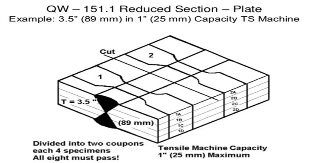
Each specimen shall be tested and shall meet minimum strength requirements as specified in the section. Whenever multiple specimens are taken all of the specimens required to represent the full thickness of the weld at one location shall comprise a set.
Bend Specimen Location:
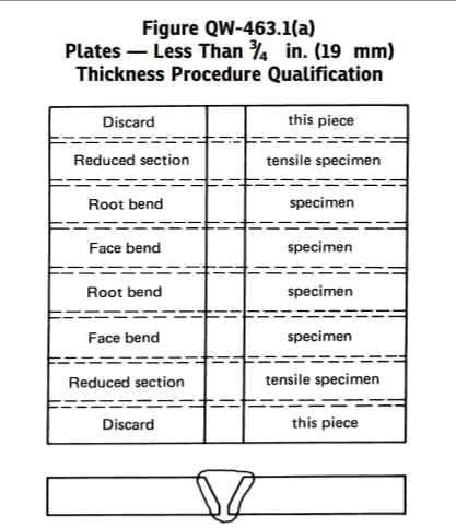
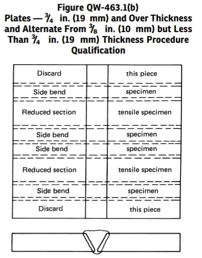
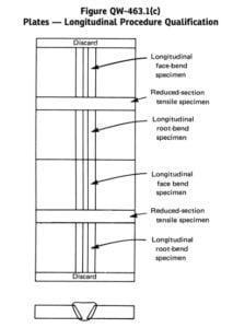
Guided Bend test welding specimen quantity depends upon the thickness of the test coupon as specified in table QW-451.1. For thickness less than 10mm two face bend and two root bend specimen are mandatory to be tested, for thickness above 10mm but less than 19mm either two face bend and two root bend specimen or four side bend test specimen are mandatory to be tested. For thickness equal and above 19mm four side bend test in welding are mandatory to be tested. For materials which have elongation less than 3% macro-each specimen required to use in lieu of guided bend test(root bend and face bend).
Transverse Side Bend Test: One side of the weld surfaces becomes convex of bend specimen.
Transverse Face Bend Test: Weld Face surface becomes the convex side of bent specimen.
Transverse Root Bend Test: Weld Root surface becomes the convex side of bent specimen.
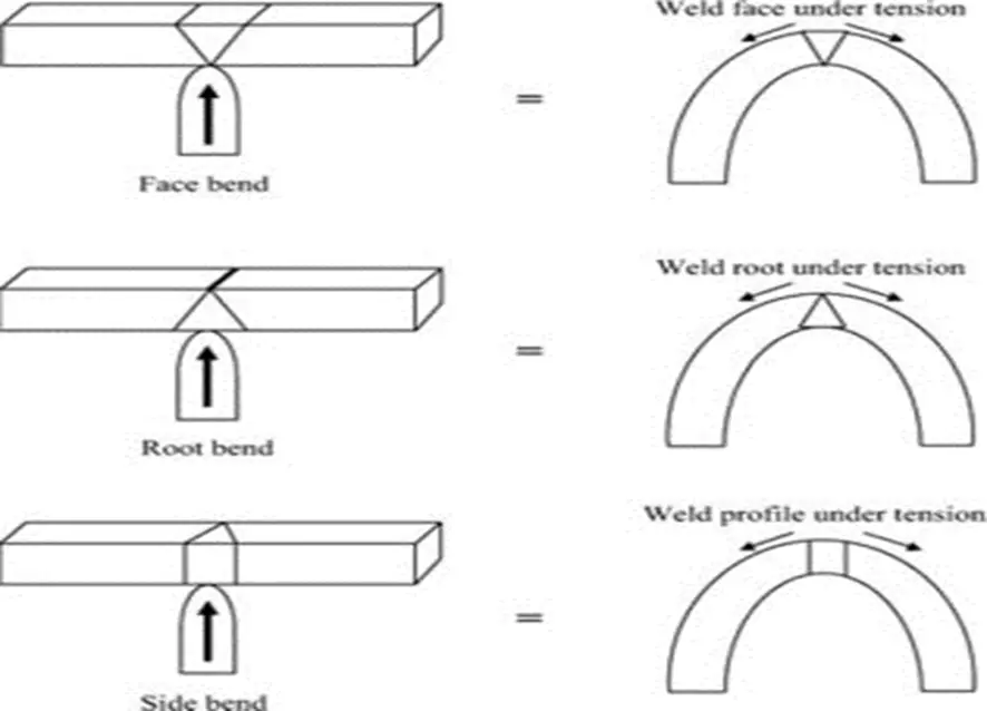
Transverse Bend Test showing bend faces
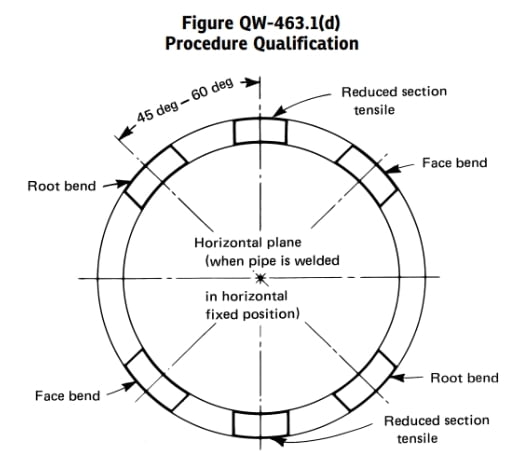
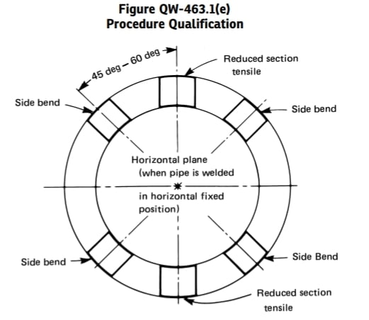
Location of Specimen for Mechanical Testing:
Specified number of specimen in Table QW-451.2 for tensile and guided bend test to be drawn from test coupon as per the location specified in ASME BPVC section IX. Fig. QW-463.1(a) to QW-463.1(e) for plate and pipe test coupon. The fig. are given below for quick reference
Acceptance of Mechanical testing
Tension Test: Acceptance criteria for tensile test as per section IX is specified in QW153 and minimum tensile required in specified in table QW/QB-422. Tensile test is acceptable as per section IX if below mentioned requirements are met,
Tensile specimen tensile strength shall not be less than the below mentioned
a) The Minimum specified tensile strength of the base material.
b) The minimum specified tensile strength of weaker of the two, if base metal of different tensile strengths is used.
c) Minimum specified tensile strength of the weld if construction code allow use of weld with less tensile strength at room temperature compared to base metal
d) If the specimen breaks in the base metal outside of the weld or weld interface, the test shall be accepted as meeting the requirements, provided the strength is not more than 5% below the minimum specified tensile strength of the base metal.
Tensile Strength = Maximum Load/ Area of Specimen
Examples for above tensile test acceptance criteria
| Base Metal (Minimum specified T.S.) | Welding Electrode (Minimum specified T.S.) | Tensile Specimen T.S. | Result Acceptable/ Unacceptable | Reason |
| SA-516 Gr. 60) (415MPa) | E7018 (490MPa) | 520MPa | Acceptable as per (a) | Specimen strength is higher than Base metal & Weld Metal strength |
| SA-516 Gr. 60) (415MPa) to SA-516 Gr. 70 (485Mpa) | E7018 (490MPa) | 460Mpa (Broken at SA-516 Gr. 60 Side) | Acceptable as per (b) | Specimen strength is higher than Base metal strength of weaker of the two |
| SA-516 Gr. 70 (490MPa) | E6013 (430MPa) | 460MPa (Broken at Weld) | Acceptable as per (c) | Specimen strength is higher than weld metal strength but less than base metal strength if construction code allow use of weld with less tensile strength at room temperature compared to base metal than acceptable |
| SA-516 Gr. 70 (490MPa) | E6013 (430MPa) | 460MPa (Broken at Weld) | Unacceptable as per (c) | Specimen strength is higher than weld metal strength but less than base metal strength, if construction code does not allow use of weld with less tensile strength at room temperature compared to base metal than unacceptable |
| SA-516 Gr. 70 (485MPa) | E7018 (490MPa) | 475MPa (Broken at SA-516 Gr. 70 Side) | Acceptable as per (d) | Broken at base material with specimen strength within 5% of base material strength |
Guided Bend Test Acceptance:
Bend test acceptance (face bend and root bend) criteria is as below
Groove Weld: The guided‐bend specimens shall have no open discontinuity in the weld or heat‐affected zone exceeding 1/8 in. (3 mm), measured in any direction on the convex surface of the specimen after bending. Open discontinuities occurring on the corners of the specimen during ASME testing shall not be considered unless there is definite evidence that they result from lack of fusion, slag inclusions, or other internal discontinuities.
Weld Overlay : When testing for corrosion‐resistant weld overlay cladding, no open discontinuity exceeding1/16 in. (1.5 mm), measured in any direction, shall be permitted in the cladding, and no open discontinuity exceeding 1/8 in. (3 mm) shall be permitted along the approximate weld interface.
There may be any number of defects as long as any one defect does not exceed 3mm as per interpretation number –IX-81-1.
Good information
Good information …Share information regarding WPS Qualifications as per SEC 9.
Thanks. We will publish article on WPS very soon.
Nicely put together and knowledgeable.
Great job done.
Simple and solid.
Very good ready reckoner for all the inspectors whenever they visit vendor shops during surveillances, even at site to quickly refer and will eventually avoid show stoppers in quickly accepting and move forward into the progress of the jobs during day to day function.
Really helpful
You guys are doing very good work to refresh the welding knowledge daily. Keep it up
Good work… Summarised information from Code ..
It is helpful for new comers who will be referring ASME Section IX…
Really nice piece of information.
Every thing is very categorized
Provided information can be useful to across the class junior to experienced
Keep posting
Nice articles testing for pqr