Welding is both an art and a science, where precision meets craftsmanship. Whether you’re a seasoned professional or just starting your welding journey, understanding and controlling welding parameters is the cornerstone of producing strong, high-quality welds. These parameters act as the recipe for your weld—get them right, and you’ll create flawless joints; get them wrong, and you’ll face defects, weak bonds, and costly rework.
In this comprehensive guide, we’ll dive deep into the critical welding parameters that determine weld quality, exploring how each factor influences the final result and providing practical insights to help you optimize your welding process.
What Are Welding Parameters?
Welding parameters are the controllable variables that directly affect the welding process and the quality of the resulting weld. These variables determine heat input, penetration depth, bead appearance, and overall weld integrity. Think of them as the dials and switches that transform raw materials into permanent, reliable connections.
The primary welding parameters include current, voltage, travel speed, electrode angle, and polarity, among others. Each parameter interacts with the others, creating a complex relationship that experienced welders learn to balance through knowledge and practice.
The Critical Welding Parameters Explained
1. Welding Current (Amperage)
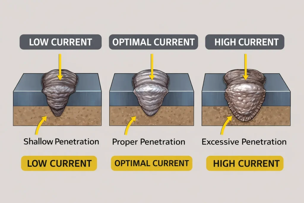
Welding current is arguably the most influential parameter in the welding process. Measured in amperes (A), it determines the amount of heat generated at the arc and directly affects penetration depth and deposition rate.
How Current Affects Your Weld:
- Higher Current: Produces deeper penetration, faster melting rates, and higher deposition. However, excessive current can cause burn-through on thin materials, excessive spatter, and undercut.
- Lower Current: Results in shallow penetration and slower melting. Too low, and you’ll experience poor fusion, cold laps, and unstable arcs.
The optimal current depends on electrode size, material thickness, welding position, and joint configuration. For example, a 3.2mm (1/8″) electrode typically operates between 90-150 amps for flat position welding on mild steel.
Pro Tip: Start with manufacturer recommendations for your electrode size, then adjust based on the specific application. Listen to the arc—a smooth, crackling sound indicates proper current, while a harsh, sputtering noise suggests it’s too high.
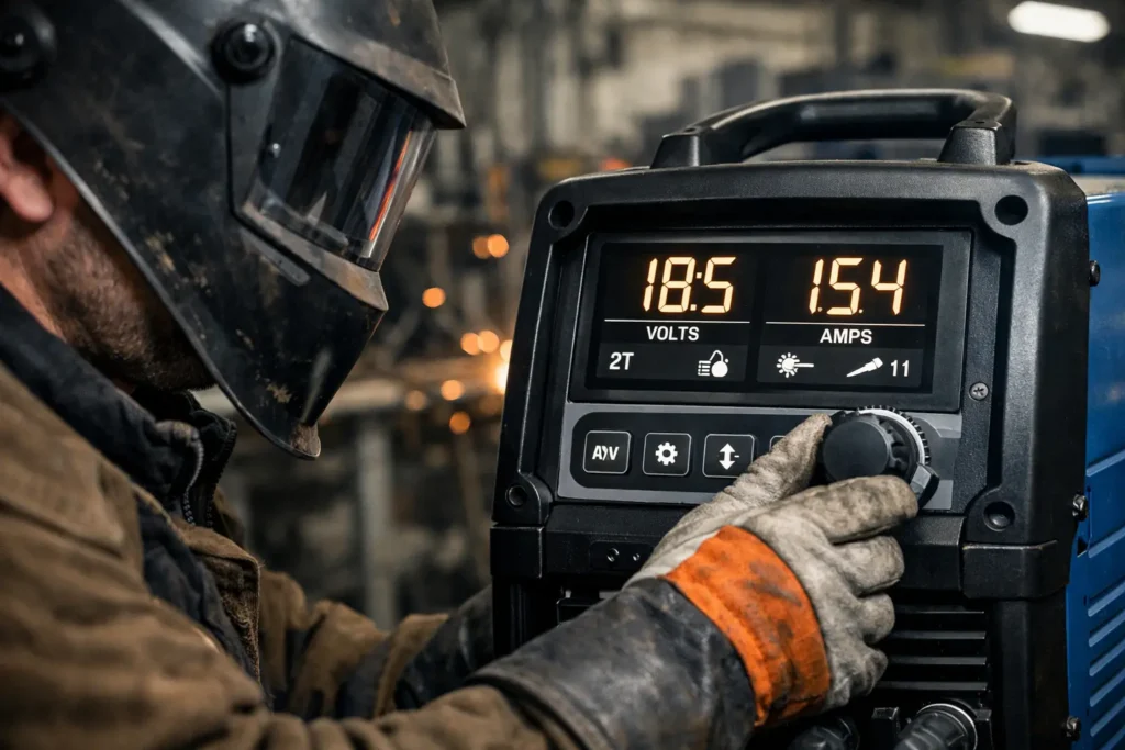
2. Welding Voltage (Arc Voltage)
Voltage controls the arc length and width of the weld bead. In most welding processes, voltage and arc length are directly proportional—higher voltage creates a longer arc.
Voltage Impact on Weld Characteristics:
- Higher Voltage: Produces a flatter, wider bead with less penetration. It increases spatter and can lead to porosity and undercut if too high.
- Lower Voltage: Creates a narrower, more convex bead with deeper penetration. Too low causes stubbing (electrode sticking to the work), poor bead appearance, and inconsistent arc.
In MIG welding, voltage is particularly critical as it works in tandem with wire feed speed. The voltage-to-current relationship creates what’s known as the “arc characteristic curve,” which determines whether you achieve spray transfer, short circuit transfer, or globular transfer.
For SMAW (Stick) welding, maintaining proper arc length (roughly equal to the electrode core diameter) naturally establishes the correct voltage. In GMAW (MIG) and GTAW (TIG), voltage is independently adjustable and requires careful tuning.
3. Travel Speed
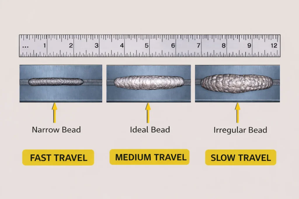
Travel speed—how fast you move the electrode or welding torch along the joint—dramatically affects heat input, penetration, and bead appearance.
Travel Speed Considerations:
- Too Fast: Produces narrow, convex beads with insufficient penetration, poor fusion, and potential undercut. The weld doesn’t have enough time to properly fuse with the base metal.
- Too Slow: Creates excessive heat input, leading to wide, flat beads, possible burn-through on thin materials, and increased distortion. You’re essentially overheating the weld zone.
The ideal travel speed allows the arc to stay in the leading third of the weld pool, ensuring proper penetration while maintaining a consistent bead width typically 2-3 times the electrode diameter.
4. Electrode/Wire Feed Speed
In wire-feed processes like MIG and flux-cored welding, wire feed speed (measured in inches per minute or IPM) works alongside voltage to control the welding process.
The wire feed speed determines deposition rate and, combined with voltage, establishes the mode of metal transfer. The relationship between wire feed speed and voltage must be balanced:
- If wire feed speed is too high for the voltage, the wire will stub into the workpiece
- If wire feed speed is too low for the voltage, the wire will burn back excessively, creating spatter
Modern MIG machines often use synergic controls that automatically adjust voltage when you change wire feed speed, simplifying setup for less experienced welders.
5. Electrode Angle and Work Angle
Electrode positioning significantly affects weld penetration, bead shape, and quality, yet it’s often overlooked by beginners.
Work Angle: The angle of the electrode in relation to the joint itself. For example, in a T-joint, positioning the electrode at 45 degrees to each surface distributes heat evenly between both pieces.
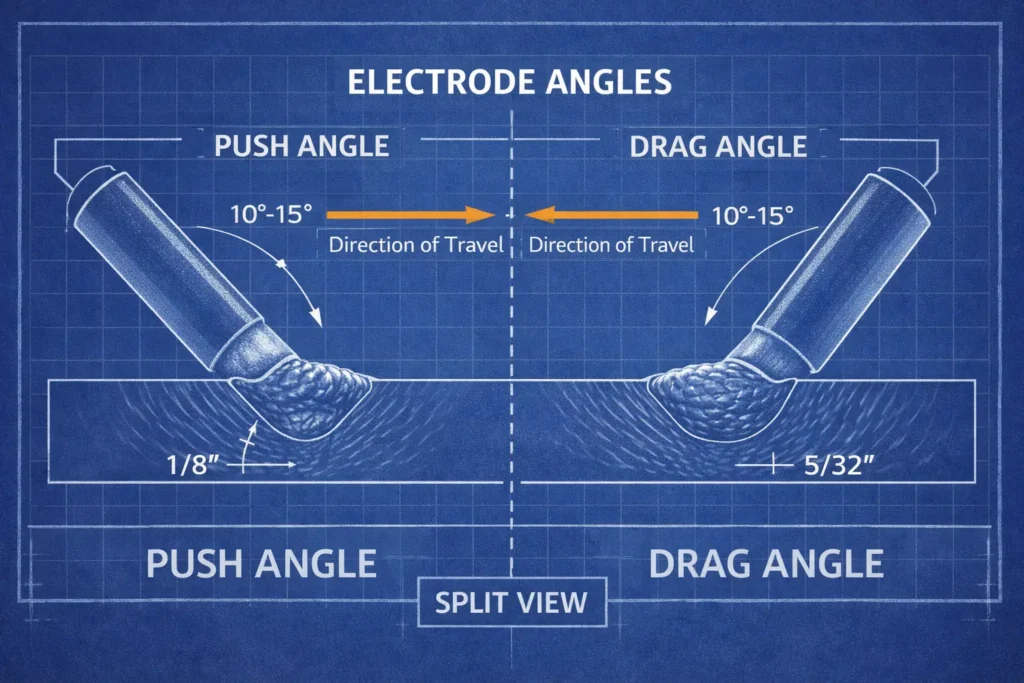
Travel Angle: The angle in the direction of travel. This can be:
- Push Angle (Forehand): Electrode points in the direction of travel (5-15 degrees). Produces less penetration, wider beads, better for thin materials.
- Drag Angle (Backhand): Electrode points opposite to travel direction (5-15 degrees). Creates deeper penetration, narrower beads, ideal for thicker materials.
6. Shielding Gas Flow Rate and Composition
For GMAW, GTAW, and FCAW processes, shielding gas protects the molten weld pool from atmospheric contamination.
Flow Rate: Typically 15-25 cubic feet per hour (CFH) for MIG welding. Too little causes porosity from inadequate protection; too much creates turbulence that actually draws in contaminants and wastes gas.
Gas Composition: Different gases produce different arc characteristics:
- 100% CO2: Deep penetration, economical, but rough arc and more spatter
- 75% Argon/25% CO2: Smooth arc, less spatter, excellent for mild steel
- 90% Argon/10% CO2: Even smoother, ideal for thin materials
- 100% Argon: Used for aluminum and stainless steel, produces minimal spatter
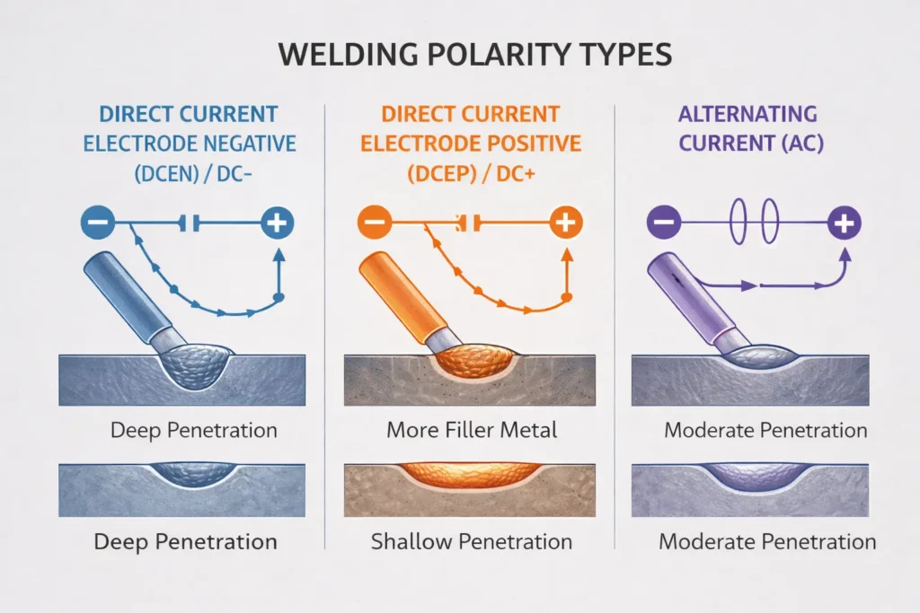
7. Polarity
Polarity determines the direction of current flow and significantly affects penetration and heat distribution.
Direct Current Electrode Positive (DCEP/Reverse Polarity): The electrode is positive. Provides deeper penetration and better cleaning action. Used for most MIG welding and TIG welding of aluminum.
Direct Current Electrode Negative (DCEN/Straight Polarity): The electrode is negative. Produces less penetration but faster deposition. Common in TIG welding of steel and some stick electrodes.
Alternating Current (AC): Current alternates between positive and negative. Provides balanced heating and excellent cleaning action. Standard for TIG welding of aluminum.
8. Preheat and Interpass Temperature
While not always adjusted during welding, temperature control is crucial for certain materials and thicknesses.
Preheat: Warming the base metal before welding (typically 200-400°F for certain steels) reduces cooling rates, minimizes hardening, and prevents cracking in thick sections or high-carbon steels.
Interpass Temperature: The maximum temperature the weld should reach between passes in multi-pass welding. Controlling this prevents overheating and maintains proper microstructure.
9. Stick-Out (Electrode Extension)
The distance the electrode extends beyond the contact tip affects resistance heating and deposition efficiency.
For MIG welding, typical stick-out is 3/8″ to 1/2″ for short circuit transfer and up to 3/4″ for spray transfer. Longer stick-out increases resistance heating in the wire, raising deposition rates but reducing penetration. Some processes, like flux-cored arc welding, intentionally use longer stick-out to preheat the wire.
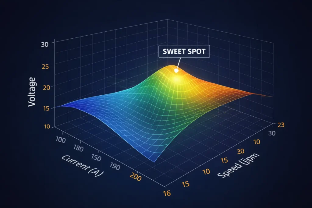
How Welding Parameters Interact
Understanding individual parameters is important, but mastering welding requires recognizing how they interact. This interplay creates what welders call “the weld window”—the range of settings that produce acceptable results.
Heat Input: The combined effect of current, voltage, and travel speed determines total heat input, calculated as:
Heat Input (kJ/inch) = (Voltage × Current × 60) / (Travel Speed in inches/min × 1000)
Managing heat input is critical for controlling distortion, preventing burn-through, and maintaining proper metallurgical properties.
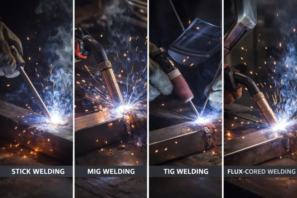
Process-Specific Parameter Considerations
SMAW (Stick Welding)
Stick welding relies heavily on welder technique since you primarily control only current. Arc length management becomes critical, as it directly affects voltage. The electrode coating type also influences parameters—fast-freeze electrodes work well with drag technique and DCEP, while fill-freeze electrodes often perform better with slight push angles.
GMAW (MIG Welding)
MIG welding offers the most adjustability with independently controlled voltage and wire feed speed. The metal transfer mode (short circuit, globular, or spray) depends on parameter combinations. Short circuit transfer (lower voltage/current) suits thin materials, while spray transfer (higher settings with argon-rich gases) provides smooth, spatter-free welds on thicker sections.
GTAW (TIG Welding)
TIG welding provides the finest control, with independent adjustment of current, filler addition, and arc length. Pulsing capabilities on modern machines allow welders to alternate between high and low current, reducing overall heat input while maintaining penetration—ideal for thin materials and out-of-position welding.
FCAW (Flux-Cored Arc Welding)
Flux-cored welding typically uses higher voltage than solid wire MIG at similar currents, producing a more fluid weld pool. Self-shielded flux-cored wires eliminate the need for shielding gas but require attention to proper voltage and stick-out to ensure adequate flux coverage.
Common Parameter-Related Defects and Solutions
Understanding how incorrect parameters cause defects helps you troubleshoot and adjust:
Porosity: Often caused by insufficient gas flow, contaminated surfaces, or excessive travel speed preventing proper shielding.
Undercut: Results from excessive current, high voltage, or incorrect electrode angle. The weld metal melts the base metal edge but doesn’t fill the groove.
Lack of Fusion/Cold Lap: Insufficient current, excessive travel speed, or incorrect electrode angle prevents the weld from bonding to the base metal or previous passes.
Excessive Spatter: Typically high current, excessive voltage, improper polarity, or contaminated surfaces.
Burn-Through: Excessive current or slow travel speed on thin materials creates holes rather than welds.
Cracking: Can result from excessive heat input causing hot cracking, or insufficient preheat causing cold cracking in susceptible materials.
Practical Tips for Parameter Optimization
Start with Recommendations: Use electrode manufacturer guidelines as your baseline, then fine-tune based on results.
Change One Parameter at a Time: When troubleshooting, adjust only one variable so you can identify its specific effect.
Create Test Coupons: Before tackling critical welds, make test welds on scrap material of the same thickness and position. This lets you verify parameters without risk.
Document Your Settings: Keep a welding procedure specification (WPS) or personal notebook recording successful parameter combinations for different materials, thicknesses, and positions.
Consider the Environment: Wind, humidity, and ambient temperature affect shielding gas coverage and cooling rates. Be prepared to adjust when conditions change.
Advanced Parameter Control
Modern welding equipment offers sophisticated parameter control beyond basic settings:
Pulse Welding: Alternating between peak and background current provides better control over heat input and puddle fluidity, particularly valuable for thin materials, out-of-position welding, and aluminum.
Synergic Control: The machine automatically adjusts voltage when you change wire feed speed, maintaining optimal arc characteristics. This simplifies setup but can limit fine-tuning capability.
Wave Form Control: Advanced inverter machines let you shape the AC wave form in TIG welding, controlling cleaning action versus penetration by adjusting the balance and frequency.
Adaptive Control: Some robotic and automated systems use sensors to monitor the weld pool and automatically adjust parameters in real-time, maintaining consistency even with joint variations.
Material-Specific Parameter Considerations
Mild Steel: Most forgiving material, accepts wide parameter ranges. Generally uses DCEP polarity and can be welded with most processes.
Stainless Steel: Requires lower heat input than mild steel (about 10-15% less current) to prevent carbide precipitation and maintain corrosion resistance. Shorter arc lengths help minimize oxidation.
Aluminum: High thermal conductivity requires higher heat input than steel. AC current in TIG provides necessary cleaning action. Argon shielding is mandatory. Requires scrupulously clean surfaces.
Cast Iron: Needs low heat input and often preheat to prevent cracking. Small diameter electrodes with low current minimize stress.
Conclusion
Mastering welding parameters transforms welding from guesswork into a controlled, predictable process. While the interaction between current, voltage, travel speed, and other variables can seem complex, systematic practice and observation develop the intuition that separates competent welders from true craftspeople.
Remember that parameters aren’t isolated numbers on a machine—they’re tools for controlling heat, managing the weld pool, and ultimately determining whether your welds meet structural, aesthetic, and quality requirements. Start with established guidelines, understand how each parameter affects the weld, observe the results carefully, and adjust methodically.
The path to welding mastery is paved with countless welds, each one teaching you something about how parameters influence outcomes. With the knowledge from this guide, you’re equipped to approach every weld with confidence, knowing you can dial in the perfect settings for any situation.
Whether you’re welding a critical structural component or practicing your technique, remember: the right parameters are the foundation of every quality weld. Take the time to understand them, document what works, and never stop learning from each bead you lay.