Coating Defects: Types, Causes & Challenges in Industrial Protective Coatings
Coating defects are among the most costly and preventable causes of premature asset failure in the process industries. Whether the structure is a crude oil storage tank, an offshore jacket, a pressure vessel, or a bridge girder, the protective coating system is the primary barrier between the steel substrate and a hostile environment. When defects form — through poor surface preparation, incorrect application, unfavourable ambient conditions, or inappropriate product selection — that barrier is compromised. The consequences range from cosmetic blemishes that require rework to severe underfilm corrosion that demands full blast and repaint at significant cost.
This guide provides a technically rigorous examination of the nine most common coating defects encountered in industrial and structural applications: sagging, blistering, cracking, pinhole formation, flash rusting, wrinkling, chalking, underfilm corrosion, and peeling. For each defect, you will find a clear description, the root causes behind it, the specific challenges it creates for inspection and maintenance teams, and the preventive measures that reduce its likelihood. Understanding these defects in detail is essential for corrosion engineers, coating inspectors, QA/QC personnel, and project managers responsible for asset integrity.
Protective coatings work in concert with other corrosion mitigation strategies — including material selection for aggressive service environments and metallurgical considerations at weld zones. Getting the coating right from day one is far cheaper than intervention after failure has occurred.
Surface Preparation: The Foundation of Every Coating System
Before examining individual defects, it is worth establishing the single most important principle in protective coating work: the condition of the substrate at the moment of application determines the performance of everything applied above it. Industry data consistently shows that more than 70% of coating failures can be traced directly to inadequate surface preparation — not to product quality or application technique.
Surface preparation removes mill scale, existing rust, chloride contamination, oil, grease, and previous coating residues that would otherwise compromise adhesion. Abrasive blast cleaning (grit blasting) remains the gold standard, creating both the required cleanliness level and the anchor profile that locks the primer mechanically to the steel. Power tool cleaning methods (SSPC-SP 11) are acceptable for localised repairs, but generally cannot achieve the profile consistency of blasting.
Common Coating Defects: Descriptions, Causes, and Challenges
1. Sagging
Sagging is the downward gravity-driven flow of the wet paint film, producing drips, runs, or curtain-like thick ridges on vertical surfaces. It is one of the most visually obvious defects and is routinely caught by inspection before the coat has fully cured.
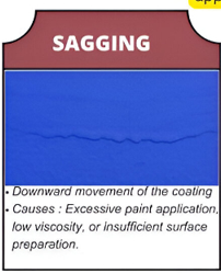
Root causes: Excessive wet film thickness per pass is the primary cause, often due to applicator technique (holding the spray gun too close or moving too slowly). Low coating viscosity — caused by over-thinning, elevated temperature, or using an incorrect thinner — also promotes sag. Application to a substrate that is above the maximum acceptable temperature accelerates viscosity drop.
Challenge: Sagging creates areas of uneven DFT: the thick sag zone and the thin zone adjacent to it. Thin zones fall below the minimum specified DFT, leaving inadequate corrosion protection. Cured sags must be sanded back or removed, which risks cutting through to the primer or substrate in the adjacent thin zone. On complex geometry (flanges, nozzles, structural steel), sagging is difficult to see during application and easy to miss until the film has cured.
Prevention: Apply coating in multiple thin passes within the manufacturer’s recommended wet film thickness per pass. Monitor WFT during application using a wet film thickness comb (per ASTM D4414). Maintain material temperature and ambient temperature within specified limits. Ensure thinner type and addition rate comply with the product data sheet.
2. Blistering
Blistering is the formation of raised bubble-like formations in the cured coating film, caused by the accumulation of liquid or vapour at the coating–substrate interface or between coats.
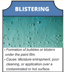
Root causes: Osmotic blistering occurs when moisture permeates the coating film and accumulates at a contamination site on the steel — soluble salts (particularly chlorides) create an osmotic cell that draws in more water. Application of coating to a substrate at or below the dew point allows condensation to form directly under the film. Coating over a surface that is too hot causes solvent to vapourise faster than the film can release it.
Challenge: Blisters weaken adhesion progressively. Once blistering starts, it rarely stops: the osmotic mechanism is self-sustaining as long as moisture can permeate the film. The contents of blisters are often acidic or chloride-bearing, which accelerates under-film corrosion. Inspecting for early-stage blistering on large immersed or buried structures is challenging — routine visual inspection is limited to accessible above-grade surfaces.
Prevention: Ensure soluble salt levels on the blast-cleaned surface are below the specified limit (commonly 20 mg/m² chloride per ISO 8502-9 / Bresle patch test). Verify substrate temperature is at least 3 degrees C above the calculated dew point before applying any coat. Avoid application to overheated surfaces (generally above 60 degrees C unless specifically approved). Select coating systems with low moisture vapour permeability for immersed or high-humidity environments.
3. Cracking
Cracking refers to ruptures of the cured coating film, ranging from fine surface crazing (checking) to deep through-thickness cracks (alligatoring or mud-cracking) that expose the substrate.
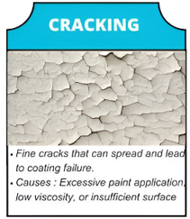
Root causes: Excessive DFT is the most common cause of mud-cracking, particularly in zinc silicate primers which shrink significantly during moisture-cured crosslinking. Internal stresses accumulate during cure; if they exceed the film’s tensile elongation, the film cracks. Applying a rigid topcoat over a more flexible intermediate coat creates interlayer stress, especially under thermal cycling. Aged coatings lose plasticisers and become brittle, developing inter-coat cracks over time.
Challenge: Cracks propagate rapidly under thermal cycling and mechanical vibration. Even fine surface cracks provide pathways for moisture and chlorides to reach the steel. Crack repair is difficult: the cracked coat must be removed to sound substrate before recoating, as applying a new coat over cracks simply buries the defect. Mud-cracking in inorganic zinc primers invalidates the primer’s function and requires full re-blast and reprime of the affected area.
Prevention: Apply zinc silicate primers strictly within the maximum single-coat DFT stated on the product data sheet (typically 75–100 µm). Select coating systems with compatible flexibility characteristics across all coats. On structures subject to significant thermal cycling (hot lines, cryogenic equipment), specify coatings with appropriate elongation-at-break values. Allow adequate overcoat time between coats to allow solvent release before applying the next layer.
4. Pinhole Formation
Pinholes are tiny through-coat perforations in the cured film, visually similar to pinpricks. In high-performance or immersion service, pinholes are completely unacceptable and must be repaired before the coated item enters service.
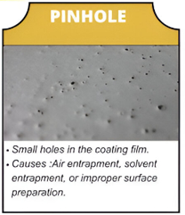
Root causes: Solvent entrapment is the primary mechanism: if the coating film skins over before the solvent beneath it has fully escaped, the trapped solvent eventually bursts through the partially cured film, leaving a tiny crater or pinhole. Application at high humidity promotes rapid surface skinning. Applying the coating to a porous substrate (e.g., concrete, previously weathered zinc coating) can also cause substrate outgassing through the fresh film. Using an incorrect nozzle size or spray pressure can create poor atomisation that traps air.
Challenge: Pinholes are difficult to detect visually on large surface areas with complex geometry. Holiday testing — using a low-voltage wet sponge (per NACE SP0188 / AS 3894.1) for coatings below 500 µm DFT, or high-voltage spark testing for thicker systems — is the standard method for locating them. In immersion service (tank linings, subsea coatings), even a single unrepaired pinhole can initiate severe localised corrosion that propagates beneath the intact film.
Prevention: Ensure adequate dry film build per coat, avoiding under-application that reduces film density. Apply coatings when relative humidity is below 85% and within the product’s specified temperature window. Use back-rolling or back-brushing after spray application to break entrained air bubbles in high-build coatings. Conduct 100% holiday testing before placing coated items in service.
5. Flash Rusting
Flash rusting is the formation of rust on a freshly blast-cleaned steel surface within hours — or sometimes minutes — of achieving the required cleanliness standard, caused by exposure to moisture before the primer coat is applied.
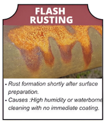
Root causes: The freshly blasted steel surface is highly reactive — the removal of mill scale and rust exposes a bare, high-energy surface with an anchor profile that vastly increases the contact area available for oxidation. High relative humidity, rain, condensation, or the residual moisture from waterborne blasting media accelerates oxidation. Chloride-contaminated blasting abrasive can also initiate flash rusting. Higher ambient temperatures combined with high humidity during early evening cooling cycles are a common field scenario.
Challenge: Flash rust degrades adhesion significantly because it creates a loose, poorly bonded iron oxide layer between the primer and the steel. Light (straw-coloured) flash rust is generally considered acceptable if wire-brushed or blown off before priming. Medium to heavy flash rust (SSPC-VIS 4 / NACE VIS 8 levels FR-2 and FR-3) typically requires re-blasting or mechanical preparation before priming can proceed. Flash rusting is particularly problematic in tropical, marine, and high-humidity environments where the safe blasting window can be as short as 30–60 minutes.
Prevention: Minimise time between blast and prime to within the safe window (typically 4 hours in dry conditions, sometimes as little as 30 minutes in high humidity). Apply a flash rust inhibitor wash primer when long delays are unavoidable. Use dehumidification equipment inside enclosed spaces to control relative humidity below 50% during blasting and priming. Monitor dew point continuously and stop blast-prime operations when conditions deteriorate.
6. Wrinkling
Wrinkling is a surface deformation of the cured coating film in which the film buckles into a ridged, wrinkled pattern resembling the surface of a prune. It occurs when the outer surface of a thick wet film cures faster than the layer below it.
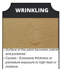
Root causes: Wrinkling is almost exclusively a problem with oxidative-cure coatings (alkyds, alkyd-modified systems) applied at excessive thickness. The outer film surface polymerises rapidly on exposure to air, while the interior beneath it remains wet. As the interior cures and shrinks, it applies tension to the already-rigid outer skin, which buckles. Elevated temperature accelerates surface cure, increasing the differential cure rate and the likelihood of wrinkling. Applying a fresh coat of alkyd before the underlying coat has fully hardened can also trigger wrinkling in the new coat.
Challenge: Wrinkled coatings have significantly reduced adhesion and film continuity. The ridged surface traps moisture, dirt, and contaminants, accelerating localised corrosion. Repair requires complete removal of the wrinkled coat by mechanical abrading or solvent stripping, followed by reapplication in correct thickness per pass. Wrinkling tends to occur on broad flat horizontal surfaces where applicators are tempted to apply heavy single coats for productivity reasons.
Prevention: Apply alkyd and oil-modified coatings in thin coats within the manufacturer’s recommended WFT range. Avoid coating in direct sunlight or on hot surfaces. Allow each coat to cure fully (hardness test per ASTM D3363 pencil hardness) before applying the next. Do not use accelerators or catalysts with alkyd systems without manufacturer approval, as these can increase surface cure rate differentially.
7. Chalking
Chalking is the gradual formation of a powdery, chalk-like residue on the outer surface of a cured coating, caused by the photodegradation of the resin binder under UV radiation.
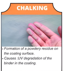
Root causes: UV radiation breaks down the polymer chains in the coating binder, releasing loose pigment particles that accumulate on the surface. Epoxy topcoats are inherently susceptible to chalking and are generally not recommended as the final coat on surfaces with continuous outdoor UV exposure. Inappropriate topcoat selection for the exposure environment is therefore the root cause. Higher UV intensity (tropical or high-altitude locations), thin film build, and pigment type all influence the rate of chalking.
Challenge: Chalking is primarily an aesthetic defect in its early stages, but as the binder continues to erode, the film thickness decreases progressively. Once chalking begins eroding the intermediate coat, corrosion protection is compromised. The chalked surface requires washing and mechanical preparation before overcoating; the loose powder will otherwise prevent adhesion of the new coat. Rate of chalking is rated per ASTM D4214 using rubbing panels.
Prevention: Specify polyurethane or fluoropolymer topcoats for all surfaces with prolonged UV exposure. These binders resist UV degradation far more effectively than epoxies. Where an epoxy intermediate coat is required for chemical resistance or DFT build, apply a UV-stable topcoat above it. Incorporate scheduled maintenance recoating into the asset inspection programme before film erosion reaches a critical level.
8. Underfilm Corrosion
Underfilm corrosion is corrosion of the steel substrate occurring beneath an apparently intact coating film. It is particularly insidious because it can spread extensively before becoming visible at the surface as blistering, discolouration, or film lifting.
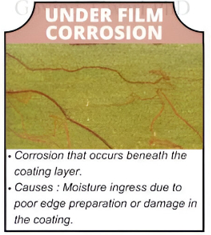
Root causes: Residual soluble salts (chlorides, sulphates) left on the steel surface after inadequate preparation create hygroscopic sites that attract moisture through the coating film. Edge preparation failures — sharp edges, weld spatter, and crevices — are especially vulnerable because coating film thins dramatically at sharp edges (the “edge effect”), leaving inadequate protection at the most corrosion-vulnerable geometry. Mechanical damage to the coating (impact, abrasion, fastener installation) creates breach points from which corrosion spreads laterally under the film.
Challenge: Underfilm corrosion is not visible until corrosion products have built up sufficient volume to blister or lift the film above them — by which time the corrosion front may have spread tens of millimetres in all directions from the initiation site. Holiday testing and visual inspection will not detect underfilm corrosion beneath an intact film. Advanced NDT methods including electrochemical impedance spectroscopy (EIS), infrared thermography, and guided-wave ultrasonics are used in critical applications to detect this defect before visible symptoms appear.
Prevention: Achieve specified chloride levels on blasted surfaces (most offshore specifications require <20 mg/m², often tightened to <5 mg/m² for critical areas). Apply stripe coats to all edges, welds, and complex geometry before the full-area coat — this ensures adequate DFT at these vulnerable areas. Use approved edge primer formulations with higher viscosity and sag resistance. Inspect and repair mechanical damage to coatings within the specified timeframe after construction.
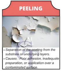
9. Peeling
Peeling is the gross detachment of the coating film from the substrate or from an underlying coat, exposing large substrate areas. It represents complete adhesion failure and is the most advanced stage of coating breakdown.
Root causes: Adhesion failure at the steel–primer interface typically results from inadequate surface preparation (contamination, insufficient anchor profile, or blast standard not achieved). Intercoat adhesion failure between two coats results from overcoating beyond the maximum recoat window, applying an incompatible topcoat chemistry, or applying the next coat over a contaminated surface. Cathodic disbondment — the electrochemical detachment of coating at cathodically protected steel surfaces — is a specific mechanism in buried or immersed structures.
Challenge: Peeling exposes large areas of bare steel to uncontrolled corrosion very rapidly. In buried pipelines or immersed structures, peeling also disrupts the cathodic protection system by increasing the bare steel area requiring protection. Cross-cut adhesion testing (ASTM D3359) and pull-off adhesion testing (ASTM D4541 / ISO 4624) should be used proactively on every project batch to detect adhesion problems before full-scale peeling occurs. Repair of peeled coatings requires full re-blast to bare metal of all peeled and at-risk areas — spot-priming over peeling edges will not prevent further detachment.
Prevention: Achieve the specified blast standard and anchor profile immediately before priming. Overcoat within the specified recoat window printed on the product data sheet. Carry out inter-coat compatibility testing when mixing products from different manufacturers or product lines. On cathodically protected structures, specify coatings tested for cathodic disbondment resistance per ASTM G8 or ASTM G42. Conduct adhesion pull-off tests per ASTM D4541 as a routine QC step after each coat.
Defect Comparison Reference Table
| Defect | Primary Cause | Corrosion Risk | Detection Method | Repair Approach |
|---|---|---|---|---|
| Sagging | Excessive WFT per pass; low viscosity | Medium | Visual (before cure) | Sand back; re-apply at correct WFT |
| Blistering | Moisture entrapment; soluble salts; near-dew-point application | High | Visual; pull-off adhesion | Remove blister; re-blast affected zone; reprime |
| Cracking | Excessive DFT; incompatible intercoat flexibility; thermal cycling | High | Visual; magnification | Remove to substrate; re-blast; full repaint |
| Pinholes | Solvent entrapment; substrate outgassing; poor atomisation | High | Holiday testing (NACE SP0188) | Spot-prime affected areas; holiday re-test |
| Flash Rusting | Moisture on freshly blasted steel before priming | High | Visual (SSPC-VIS 4) | Re-blast; prime within safe window |
| Wrinkling | Differential cure rate in alkyd; excessive DFT | Medium | Visual (early cure stage) | Strip wrinkled coat; reapply in thin passes |
| Chalking | UV binder degradation; wrong topcoat selection | Medium | Visual; ASTM D4214 rub test | Wash; mechanically prepare; apply PU topcoat |
| Underfilm Corrosion | Residual salts; edge preparation failure; film breach | Critical | EIS; IR thermography; UT; visual of blistering | Full strip to metal; re-blast; repaint entire system |
| Peeling | Adhesion failure at substrate or intercoat; cathodic disbondment | Critical | Pull-off adhesion test (ASTM D4541) | Re-blast all peeled and at-risk zones; full repaint |
Inspection Standards and Methods for Coating Work
Effective coating inspection requires systematic measurement at each stage of the process, using instruments and procedures referenced to accepted international standards. The following standards form the backbone of most industrial coating inspection programmes:
| Standard | Scope | Application Stage |
|---|---|---|
| ISO 8501-1 / SSPC-VIS 1 | Visual assessment of blast cleanliness | Post-blast, pre-prime |
| ISO 8502-3 | Dust contamination assessment | Post-blast |
| ISO 8502-9 / Bresle patch | Soluble salt (chloride) measurement | Post-blast |
| ISO 8503-1/2 | Surface anchor profile (Rz) measurement | Post-blast |
| ASTM D4414 | Wet film thickness (WFT) measurement | During application |
| SSPC-PA 2 / ISO 2808 | Dry film thickness (DFT) measurement | After each coat cures |
| NACE SP0188 / AS 3894.1 | Holiday (discontinuity) testing | After final coat |
| ASTM D4541 / ISO 4624 | Pull-off adhesion testing | After each coat cures |
| ASTM D4214 | Degree of chalking assessment | In-service inspection |
| SSPC-VIS 4 / NACE VIS 8 | Flash rust visual standards | Post-blast, pre-prime |
Challenges in Managing Coating Defects in the Field
Even when the correct specification has been written and the right products have been procured, field execution introduces a range of challenges that create conditions for defects to form. Awareness of these challenges is as important as knowledge of the defects themselves.
- Early Detection of Subsurface Defects: Pinholes and underfilm corrosion cannot be found by visual inspection alone. Routine holiday testing is time-consuming and is often cut short on large projects under schedule pressure, leaving defects undetected until they manifest as visible failure.
- Ambient Condition Control: Temperature, humidity, wind speed, and airborne contaminants during application must be continuously monitored and acted upon. Many projects lack the instrumentation or discipline to halt work when conditions fall outside specification limits.
- Surface Preparation Shortcuts: Abrasive blast cleaning is the most expensive and time-consuming step in a coating project. Under schedule and cost pressure, crews are tempted to reduce blast standard, cut preparation time, or overcoat without adequate salt testing. More than 70% of coating failures originate at this stage.
- Applicator Skill Variability: Airless spray application requires trained, experienced operators to achieve consistent WFT across complex geometry. Untrained or fatigued operators produce uneven coverage, missed areas, and excessive application in flat zones.
- Coating System Compatibility: Mixing products from different manufacturers within a multi-coat system, or overcoating beyond the maximum recoat window, creates intercoat adhesion risks that are invisible until peeling occurs in service — sometimes years later.
- Edge and Complex Geometry: Weld seams, bolt holes, free edges, stiffeners, and structural connections are where coating failures most commonly initiate. These areas are most difficult to coat consistently and most vulnerable to the edge effect that reduces DFT at sharp profiles.
- Balancing Cost, Speed, and Quality: The competitive pressure in fabrication and construction projects creates constant tension between the quality of surface preparation and application and the need to reduce costs and deliver on schedule. This is the single most persistent systemic challenge in industrial coating work.
Relationship Between Coating Defects and Corrosion
Coating defects do not cause corrosion directly — they create the conditions that allow corrosion to proceed. Understanding this relationship helps prioritise which defects require immediate action and which can be scheduled for planned maintenance. The most comprehensive treatment of corrosion mechanisms in industrial structures is provided in our guide to corrosion types, causes, and prevention.
Pinholes and underfilm corrosion are the most dangerous because they allow corrosion to establish beneath an intact coating film before any surface symptom is visible. By the time blistering or film lifting appears, the corrosion front may have spread far beyond the visible blister margin. This is particularly serious at weld seams and heat-affected zones, where local metallurgical changes can make the steel more susceptible to corrosion — an effect discussed in the context of weld decay in stainless steels and explored more broadly in the corrosion guide.
In sour service environments containing H2S, coating system selection must account for hydrogen permeation and the risk of sulphide stress cracking (SSC) at coating damage sites. Detailed guidance on materials selection for sour service is provided in the sour service article.
Coating Defect Prevention: A Systematic Approach
Preventing coating defects is far more cost-effective than detecting and repairing them after application. The following framework addresses each stage of the coating process from pre-project planning through to in-service inspection:
Specification and Product Selection
The coating system must be selected for the specific exposure environment — not selected generically from a preferred supplier list. Define the operating temperature range, chemical exposure, UV exposure, immersion conditions, and maintenance access frequency. Match the DFT specification and coating type to these requirements. Obtain written confirmation of intercoat compatibility from the coating manufacturer when using products from more than one supplier within the same system.
Pre-Application Controls
Verify that abrasive blast media meets the specification for hardness, cleanliness, and size distribution. Confirm that the substrate temperature is at least 3 degrees C above the dew point and that relative humidity is below 85% before commencing any coat. Measure soluble salt levels per ISO 8502-9 and reject the surface if results exceed the specification limit. Document all pre-application readings in a field inspection record.
Application Controls
Issue written work instructions to applicators specifying the spray equipment settings, recommended tip size, spray distance, overlap pattern, and WFT target. Use WFT combs (ASTM D4414) regularly during application on each surface zone. Confirm that material temperature and pot life are within specification before each application pot is opened.
Post-Application Inspection
Measure DFT per SSPC-PA 2 or ISO 2808 after each coat reaches minimum cure time. Conduct pull-off adhesion testing on representative areas per ASTM D4541. Perform 100% holiday testing after the final coat on all immersed and buried surfaces per NACE SP0188. Document all readings and immediately flag non-conforming readings for review and disposition by the responsible inspector.
In-Service Inspection
Establish a scheduled inspection programme that includes visual inspection for chalking, blistering, cracking, and peeling at defined intervals appropriate to the exposure environment. Carry out DFT measurement on suspect areas using portable magnetic gauges. On high-criticality structures, employ advanced NDT methods such as infrared thermography or EIS to detect underfilm corrosion that is not yet visible. Address minor defects during planned maintenance windows before they escalate to large-scale failures requiring full blast and repaint.
Key Takeaways
- Over 70% of coating failures originate from inadequate surface preparation — blast standard, cleanliness, anchor profile, and soluble salt removal are non-negotiable.
- Environmental monitoring (temperature, humidity, dew point) must be continuous during application and must trigger work stoppages when conditions are outside specification.
- Pinhole formation and underfilm corrosion are the highest-risk defects because they are difficult or impossible to detect visually — holiday testing and advanced NDT are required.
- Flash rusting must be controlled by minimising blast-to-prime intervals and using environmental controls — re-blasting is the only acceptable corrective action for medium to heavy flash rust.
- Stripe coats on all edges, welds, and complex geometry are essential for achieving specified DFT at the most corrosion-vulnerable locations.
- Selecting the right coating chemistry for the UV exposure, chemical, and immersion environment is as important as correct application — using epoxy topcoats in direct UV exposure guarantees chalking.
- In-service inspection programmes must be established at project commissioning and executed proactively — addressing early-stage defects during planned shutdowns is orders of magnitude cheaper than emergency recoating.
Recommended Books on Protective Coatings and Corrosion
Disclosure: WeldFabWorld participates in the Amazon Associates programme (StoreID: neha0fe8-21). If you purchase through these links, we may earn a small commission at no extra cost to you. This helps support free technical content on this site.