Lack of Fusion (LOF) in Welding — Causes, Detection, Prevention, and Code Acceptance Criteria
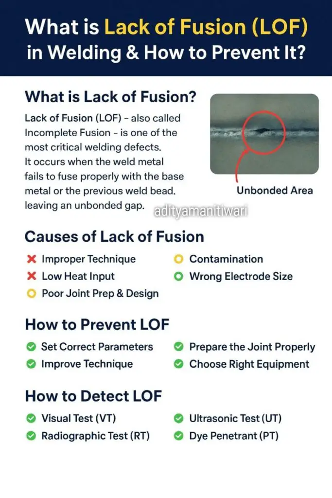
Lack of fusion (LOF) — also called incomplete fusion — is one of the most structurally dangerous weld defects encountered in fabrication. Unlike volumetric defects such as porosity, LOF is a planar discontinuity: an unbonded interface between weld metal and base metal, or between adjacent weld passes, that behaves mechanically like a pre-existing crack. Under stress, the sharp tips of an LOF defect concentrate and amplify load, making brittle fracture, fatigue cracking, or leakage far more likely than in a sound weld of the same cross-section.
For industries where weld failure has catastrophic consequences — oil and gas pressure vessels, high-energy steam piping, offshore structures, nuclear plant, and bridges — LOF is universally classified as an unacceptable defect. Every major construction code from ASME Section VIII to AWS D1.1 to ASME B31.3 rejects any weld indication characterised as lack of fusion, regardless of size.
This guide provides a complete technical reference: types and locations of LOF, root causes by welding process, heat input and joint geometry considerations, non-destructive testing (NDT) detection methods, code acceptance criteria, repair strategy, and a practical prevention framework for welders, engineers, and QA/QC inspectors.
1. What is Lack of Fusion?
Fusion welding creates a joint by melting both filler metal (if used) and a layer of base metal at the joint faces. When the melting is complete and the pool solidifies, the weld and parent metal are metallurgically bonded — they form a continuous crystalline structure across what was the interface. Lack of fusion occurs when this metallurgical bonding fails to take place: the weld metal solidifies in contact with the base metal or the previous bead, but without melting and fusing with it. The result is an interface that appears joined to visual inspection but carries virtually no load in the unfused zone.
LOF differs from lack of penetration (LOP), which is a specific failure to melt the root of the joint and is sometimes treated separately in codes. In practice the two often co-exist: a root pass with insufficient heat both fails to penetrate fully (LOP) and fails to fuse with the base metal faces (LOF). Both are crack-like and equally rejectable.
Types of LOF by Location
| LOF Type | Location | Primary Cause | Most Affected Process |
|---|---|---|---|
| Sidewall LOF | Between weld metal and groove bevel face | Arc directed to weld centre; low heat; narrow groove | SMAW, FCAW, GMAW |
| Interpass (Inter-run) LOF | Between adjacent weld passes in multi-pass welds | Insufficient remelting of previous bead; concave bead profile | All processes |
| Root LOF | At the root of first pass / root face | Insufficient root gap; excess root face; low amperage | SMAW, GTAW root pass |
| Cold Lap (Cold Lapping) | At bead toe or on surface | Weld pool flows over cold base metal without melting it | GMAW (short-circuit transfer) |
Table 1. Classification of LOF by location, mechanism, and most susceptible process.
2. Why is Lack of Fusion Dangerous?
The hazard of LOF stems directly from its geometry. A lack of fusion defect is effectively a pre-existing crack embedded in or at the boundary of the weld. The stress intensity factor at the tip of a planar defect scales with both the applied stress and the square root of the defect half-length. Even a small LOF can therefore propagate rapidly under:
- Cyclic (fatigue) loading — common in pressure vessels during start-up and shutdown cycles, and in structural members under dynamic loads.
- High static stress — particularly in restrained joints where thermal contraction during cooling creates residual tensile stress.
- Low-temperature brittle fracture — in carbon and low-alloy steels operating below the ductile-to-brittle transition temperature.
- Stress corrosion cracking (SCC) — where the notch geometry concentrates stress at a location also exposed to a corrosive environment.
In pressure vessels and piping, an LOF at the weld root of a pipe girth weld can propagate entirely through the wall during a single pressure excursion, resulting in leakage or rupture. For this reason, every major welding construction code — ASME Section VIII Div. 1 (UW-51, UW-52), ASME B31.3, AWS D1.1, and EN ISO 5817 — classifies LOF as a rejectable imperfection at any size.
3. Causes of Lack of Fusion
LOF is a process control failure. It results from one or more of the following conditions preventing the weld pool from melting and wetting the adjacent solid surface.
3.1 Insufficient Heat Input
The weld pool must have enough energy to melt through the oxide and thermal boundary layer at the groove face before it can fuse with the base metal. Heat input is governed by the relationship:
H = (V × A × 60) / (1000 × TS)
// V = arc voltage (volts), A = welding current (amps)
// TS = travel speed (mm/min)
// Efficiency factor (k) may be applied: k = 0.80 for SMAW, 1.0 for GTAW, 0.90 for GMAW
H_corrected = k × H
Low H (below the minimum qualified in the WPS) = elevated LOF risk.
Common causes of insufficient heat input: amperage set too low for the electrode diameter or material thickness; travel speed too high, moving the arc over base metal before the pool has time to melt it; and high voltage that spreads the arc energy over a wide area instead of concentrating it at the fusion line.
3.2 Incorrect Electrode or Torch Angle
The direction of arc force and heat flow is strongly influenced by the electrode or torch angle. In a V-groove joint, the work angle must direct the arc toward each groove face on successive passes. If the electrode is held perpendicular to the joint centreline for every pass, the arc energy is aimed at the weld pool centre, and the groove sidewall receives only indirect heating — insufficient to melt and fuse. The correct technique is to direct the electrode toward the sidewall being fused on each pass, with a travel angle (drag or push) of 5–15 degrees from vertical.
3.3 Narrow Groove Angle or Insufficient Root Gap
Joint geometry establishes the physical access available to the electrode or torch. When the included angle of a V-groove is below approximately 60 degrees (for SMAW), the electrode shank contacts the groove wall before the tip reaches the fusion zone, deflecting the arc away from the sidewall. Similarly, an insufficient root gap in a butt joint means the root faces are too close together for the first pass to penetrate and fuse with both faces simultaneously. Correct groove geometry must be specified in the joint design and verified against the qualified WPS before welding starts.
3.4 Contaminated Joint Surfaces
Any film on the groove face that resists wetting by the molten weld pool can prevent fusion. Critical contaminants include:
- Mill scale and rust — act as thermal and chemical barriers.
- Oil, grease, and paint — decompose to generate gas films and carbon films at the interface.
- Aluminium oxide (Al2O3) — an extremely refractory ceramic (melting point ~2,050°C) that forms spontaneously on aluminium alloy surfaces. It must be mechanically removed with a clean stainless steel brush before and between passes; it cannot be relied upon to dissolve into the weld pool at typical arc temperatures.
- Moisture and condensation — particularly in cold-weather fabrication, where condensed moisture on groove faces vaporises explosively and disrupts fusion.
3.5 Oversized or Mismatched Consumable
An electrode that is too large for the root pass will bridge across the groove before the tip reaches the root, leaving unfused root faces on both sides. In fill passes, an oversized electrode may deposit a convex, high-crown bead that traps the next pass on its side without remelting the underlying bead sufficiently — creating interpass LOF. Correct electrode size selection for the pass sequence must be specified in the WPS. See the welding consumable selection guide for electrode sizing guidance.
3.6 Magnetic Arc Blow
In DC welding of ferromagnetic steels, localised magnetism in the workpiece can deflect the arc away from the fusion line — a phenomenon called magnetic arc blow. The arc wanders unpredictably, leaving intermittent zones where fusion did not occur. Remediation includes switching to AC where the process permits, repositioning the earth connection, using back-step welding sequences, and reducing current where possible.
| Cause | SMAW | GTAW | GMAW | SAW | FCAW |
|---|---|---|---|---|---|
| Low heat input | High | High | Med | Low | Med |
| Wrong electrode angle | High | Med | Med | Low | Med |
| Narrow groove / poor fit-up | High | Med | Med | Low | Med |
| Contaminated surface | Med | High | Med | Med | Med |
| Cold lapping (short-circuit) | N/A | N/A | High | N/A | Med |
| Magnetic arc blow | Med | Low | Low | Low | Low |
Table 2. Relative LOF risk by cause and welding process (High / Med / Low indicates likelihood of occurrence).
4. How to Detect Lack of Fusion
Because LOF is often fully embedded within the weld volume, surface inspection alone is insufficient for reliable detection. A combination of volumetric and surface NDT methods is typically required for critical applications.
4.1 Visual Testing (VT)
Visual testing can reveal LOF only when it breaks the weld surface or toe — for example, a cold lap at the weld toe visible as a sharp groove or overlap. Root LOF may be visible from the back side of a weld before the backing pass is deposited, if back-gouging exposes the root. VT is always the first inspection step and should be performed on every weld in good light and at appropriate angles, but it cannot detect subsurface LOF.
4.2 Radiographic Testing (RT)
Radiography detects defects as density differences on the film or digital image. For RT to reveal LOF, the X-ray or gamma-ray beam must be oriented so that it passes along the plane of the defect — typically within about 10 degrees. If the beam is perpendicular to the unfused interface (as it usually is in a standard butt weld radiograph), the tight gap of LOF does not produce enough density difference to be visible. As a result, RT has poor sensitivity to LOF and can give a false pass on welds containing LOF defects.
4.3 Ultrasonic Testing (UT)
Ultrasonic testing reflects sound waves from planar reflectors regardless of their orientation relative to the beam, making it significantly more sensitive to LOF than RT. Conventional UT using angle-beam probes (45, 60, or 70 degree refracted shear waves) can locate and size subsurface LOF reliably when performed by a qualified Level II or Level III technician. For the best results, Phased Array UT (PAUT) and Time-of-Flight Diffraction (TOFD) are preferred — both can image the weld cross-section and provide sizing data that conventional RT cannot.
4.4 Dye Penetrant Testing (PT) and Magnetic Particle Testing (MT)
Both PT and MT are surface-only methods. PT is applicable to all metallic and non-metallic materials and will reveal LOF that breaks the surface. MT is applicable to ferromagnetic steels and is more sensitive than PT for tight, surface-breaking cracks and near-surface defects. Neither method detects subsurface LOF.
| NDT Method | LOF Sensitivity | Subsurface Detection? | Applicable Materials | Notes |
|---|---|---|---|---|
| Visual Testing (VT) | Low | No | All | Surface / toe LOF only |
| Radiographic Testing (RT) | Low–Med | Yes | All | Geometry-dependent; misses tight LOF |
| Conventional UT | High | Yes | Metals | Angle-beam probes required |
| Phased Array UT (PAUT) | Very High | Yes | Metals | Best method for LOF; imaging + sizing |
| TOFD | Very High | Yes | Metals | Excellent sizing accuracy |
| Dye Penetrant (PT) | Low | No | All (clean surface) | Surface-breaking LOF only |
| Magnetic Particle (MT) | Med | Near-surface only | Ferromagnetic steels | Surface and near-surface |
Table 3. NDT method comparison for lack of fusion detection.
5. Code Acceptance Criteria for LOF
The table below summarises the acceptance position for LOF under the most commonly applied codes:
| Code / Standard | Applicable Scope | LOF Acceptance | Repair Required? |
|---|---|---|---|
| ASME Section VIII Div. 1 — UW-51 | Full RT of pressure vessels | Rejectable — zero tolerance | Yes — full excavation and re-weld |
| ASME B31.3 — Table 341.3.2 | Process piping | Rejectable — zero tolerance | Yes |
| AWS D1.1 — Table 6.1 (VT & RT) | Structural steel welding | Rejectable — all categories | Yes |
| EN ISO 5817 — Quality Level B | Fusion welds in steel, aluminium | Not permitted | Yes |
| EN ISO 5817 — Quality Level C and D | Lower quality levels | Not permitted (any level) | Yes |
| API 1104 — Section 9 | Pipeline girth welds | Rejectable | Yes |
Table 4. LOF acceptance criteria under commonly applied welding construction codes.
The only route to accepting a confirmed LOF indication without repair is through Engineering Critical Assessment (ECA) using fracture mechanics principles as described in API 579-1 / ASME FFS-1. This requires determination of the fracture toughness of the weld metal and HAZ, the stress state at the defect location, and a fitness-for-service analysis that demonstrates the defect will not grow to critical size during the design life. ECA is a specialist engineering process and is not available as a routine acceptance route in most fabrication contracts.
6. How to Prevent Lack of Fusion
Prevention of LOF is a function of proper WPS development and qualification, welder training and technique, joint preparation discipline, and in-process inspection. The most effective prevention is to address all contributing factors simultaneously — correcting only one while neglecting the others still leaves risk on the table.
6.1 Correct Heat Input Parameters
The approved WPS must specify minimum and maximum heat input (or the equivalent current, voltage, and travel speed ranges) that have been verified by PQR testing to produce full fusion. Production welding must stay within those ranges. Use the MIG settings calculator or TIG settings calculator to verify parameter compliance before committing to production runs.
6.2 Electrode and Torch Angle Technique
Train welders to direct the arc toward the fusion line on every pass, not toward the centre of the weld pool. In groove welds, alternate the work angle to address each sidewall. On cover passes, use a controlled weave or oscillation that pauses briefly at each sidewall edge to ensure fusion. Ensure welders are qualified to the relevant welding position and joint configuration under ASME Section IX or applicable standard before performing production work.
6.3 Joint Preparation and Fit-Up Control
Specify groove angle, root face dimension, root gap, and land dimension in the WPS. Verify fit-up before welding with a check template or fit-up gauge. Minimum groove included angles for common processes:
| Process | Minimum Included Groove Angle | Minimum Root Gap | Maximum Root Face |
|---|---|---|---|
| SMAW (3.2 mm electrode) | 60° | 2–3 mm | 1.5 mm |
| SMAW (4.0 mm electrode) | 60° | 3–4 mm | 1.5 mm |
| GTAW (root pass) | 60–70° | 2–3 mm | 0–1 mm |
| GMAW (spray arc) | 60° | 2–4 mm | 2 mm |
| FCAW-G | 60° | 3–5 mm | 2 mm |
| SAW | 60° (conventional) / 10–15° (narrow gap) | 3–6 mm | 3 mm |
Table 5. Indicative minimum groove geometry values by process. Always defer to the qualified WPS for project-specific requirements.
6.4 Surface Cleaning and Contamination Control
Before welding, all joint surfaces within the thermal influence zone (minimum 25 mm either side) must be clean, dry, and free of mill scale, rust, paint, grease, and moisture. Use grinding or wire brushing for scale and rust; degrease with an approved solvent; and for aluminium alloys, mechanically abrade with a dedicated stainless steel brush immediately before welding. In cold or humid environments, apply warm air drying or gentle preheat to eliminate surface moisture.
6.5 In-Process Inspection and Inter-Pass Cleaning
LOF between passes is prevented by ensuring each bead is clean, correctly profiled, and provides adequate fusion width for the next pass to remelt. Inter-pass cleaning (slag removal for SMAW and FCAW; light grinding to remove high-crown concave beads) should be verified by the welder before the next pass is deposited. In-process inspection by a qualified welding inspector is the last line of defence before the defect becomes embedded and inaccessible.
7. Repairing a Weld with Confirmed LOF
Once LOF is confirmed by NDT, repair is mandatory under all construction codes. The repair process must be controlled and documented as rigorously as the original weld.
- Locate and mark the full extent of the defect using UT (PAUT preferred) to determine length, depth, and lateral position. Mark the weld surface clearly.
- Excavate to sound material by grinding, air-arc gouging, or machining. Remove metal until a clean, bright, defect-free surface is confirmed — typically by MT or PT on the excavated cavity. The excavation must extend beyond the defect extremities by at least 10–15 mm in each direction.
- Inspect the cavity by MT or PT to confirm complete removal of the LOF. Document the result with photographs and NDT reports.
- Re-weld to a qualified repair WPS. The repair groove geometry must be appropriate for the repair process — typically a tapered channel or U-groove to allow arc access. Preheat if required by the base material and thickness.
- Post-weld NDT of the repair area using the same methods (or better) as the original inspection. All repair welds on code-stamped vessels must be documented on a Weld Repair Record and reviewed by the Authorised Inspector (AI).
8. Practical Prevention Checklist for Site Welding
Before Welding
- Verify groove angle and root gap against WPS
- Grind or brush all joint surfaces clean
- Check for moisture, oil, and paint — remove all
- Confirm preheat temperature is achieved and maintained
- Select correct electrode size for the pass sequence
- Calibrate welding machine — verify set amps and volts
During Welding
- Maintain arc length within specified limits (max 1x electrode core diameter for SMAW)
- Direct arc toward fusion zone — not pool centre
- Pause at sidewalls on weave passes
- Remove all slag and clean each pass before depositing the next
- Monitor and record interpass temperature
- Do not rush travel speed on root and sidewall passes
After Each Pass
- Inspect each pass visually before the next pass
- Grind concave or undercut bead toes before covering
- Check bead width — not more than 3x electrode diameter (SMAW)
- Ensure no cold laps visible at toes (GMAW)
After Welding
- Perform VT to full length before NDT
- Submit for UT (PAUT preferred) for critical joints
- Document all inspection results
- Investigate any LOF indication — do not re-weld without root cause analysis
Recommended References
These technical references are valuable for engineers, inspectors, and welders wanting to deepen their understanding of weld defects, NDT, and weld quality control.
Disclosure: WeldFabWorld participates in the Amazon Associates programme (StoreID: neha0fe8-21). If you purchase through these links, we may earn a small commission at no extra cost to you. This helps support free technical content on this site.