Coating & Painting Tests — The Backbone of Corrosion Protection
Coating and painting tests are the primary quality assurance mechanism that determines whether a protective coating system will perform for its intended service life — or fail prematurely and leave the structure exposed to corrosion. In industries such as Oil & Gas, Power Generation, Marine, and Civil Infrastructure, protective coatings are not decorative: they are engineered barriers against moisture, oxygen, chlorides, UV radiation, and chemical attack. A failure of even one square centimetre of coating can initiate a corrosion cell that spreads unseen beneath an otherwise intact paint film for years before surface damage becomes visible.
The entire coating lifecycle — from steel surface preparation through application, curing, and long-term service — must be verified by systematic testing. Each test stage targets a specific failure mode. Surface preparation tests ensure the substrate is free of contaminants that prevent adhesion. Environmental tests confirm conditions are suitable for application and curing. Post-application tests verify film build, adhesion strength, and cure completeness. Integrity tests locate microscopic defects invisible to the naked eye. Durability tests provide confidence that the system will withstand the real service environment.
This guide covers all major coating and painting tests in sequence, with the governing standards, typical acceptance criteria, and the practical failure modes each test is designed to prevent. Whether you are a coating inspector, QA/QC engineer, or fabrication professional, understanding these tests in depth is essential to delivering compliant, long-lasting corrosion protection on every project.
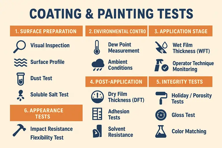
Stage 1 — Surface Preparation: Foundation of Coating Success
Surface preparation is the single most important factor governing coating performance. Published industry data and failure analysis reports consistently attribute 70–80% of all premature coating failures to inadequate surface preparation — not to coating quality or application technique. The steel surface must be free of rust, mill scale, grease, oil, soluble salts, and residual dust before any coating is applied, and it must have the correct surface roughness (anchor profile) to allow the coating to mechanically key into the substrate.
Visual Inspection
Purpose: To confirm the substrate is clean and free from rust, oil, grease, moisture, old paint, or other contaminants before blasting commences and again after blasting is complete.
Method: Direct visual examination, often supplemented by a white cloth or cotton-glove wipe test for oil and grease detection. A UV lamp may be used to detect residual oil contamination.
Standards: ISO 8501-1 (rust grades and preparation grades Sa 1, Sa 2, Sa 2.5, Sa 3), SSPC-SP 1 (solvent cleaning), SSPC-SP 6 (commercial blast).
Acceptance: For most industrial coatings on structural steel, ISO Sa 2.5 (near-white blast) is the minimum requirement. Immersion-service linings and offshore structures typically require Sa 3 (white metal).
Surface Profile (Anchor Pattern)
Purpose: To verify that blast cleaning has produced sufficient surface roughness (an “anchor pattern”) for the first coat to mechanically interlock with the steel.
Method: Three principal measurement methods are used:
- Replica tape (Testex Press-O-Film): A crushable plastic tape is pressed firmly against the blasted surface; the compressed depth is measured with a micrometer to give the peak-to-valley profile height.
- Surface comparators (ISO 8503-1): Visual comparison against calibrated reference segments (Shot, Grit, Fine, Medium, Coarse grades).
- Stylus profilometer (ISO 4287): An electronic gauge traverses the surface and outputs Ra and Rz roughness parameters.
Standards: ASTM D4417, ISO 8503-2 (replica tape), ISO 8503-4 (stylus method).
Typical range: 40–75 µm Rz for standard epoxy coating systems. Zinc-rich primers often require a minimum of 50 µm.
Dust Contamination Test
Purpose: To detect residual blast dust and steel particles remaining on the surface after blasting, which prevent intimate contact between the coating and substrate.
Method: A clear pressure-sensitive tape (minimum 25 mm wide) is pressed firmly onto the blasted surface and peeled off. The tape is then placed on a white paper background and assessed under good lighting against the ISO 8502-3 dust rating chart, which grades dust quantity (rating 0–5) and particle size (class 1–5).
Standard: ISO 8502-3.
Acceptance: Most specifications require a dust rating of 1 or less and a dust particle size class of 2 or less.
Soluble Salt Contamination Test
Purpose: To quantify chloride, sulfate, and other ionic contamination that remains on the blasted surface. Soluble salts are osmotically active and will draw moisture through the coating film, generating osmotic pressure sufficient to blister the coating from within.
Method: The Bresle patch method (ISO 8502-6): a flexible adhesive patch with a small known area (1250–2500 mm²) is pressed onto the surface, and distilled water is injected and retrieved via a syringe after a specified contact time. The extract is analysed for conductivity (ISO 8502-9), which is converted to a sodium chloride equivalent concentration.
Standards: ISO 8502-6 (Bresle sampling), ISO 8502-9 (conductivity measurement), NACE SP0508.
Acceptance: Typically ≤ 20 µg/cm² (200 mg/m²) NaCl equivalent for atmospheric service. Immersion service and offshore structures commonly require ≤ 5–10 µg/cm².
Stage 2 — Environmental Control: Right Conditions, Right Results
Environmental conditions during coating application directly affect film formation, adhesion, and cure. Paint manufacturers specify operating envelopes for temperature, relative humidity, and steel surface temperature in their product data sheets. Applying coatings outside these windows — particularly at high humidity or at a steel temperature near or below the dew point — causes predictable failures including osmotic blistering, pinholing, amine blush on epoxies, and poor adhesion.
Dew Point Measurement
Purpose: To ensure the steel surface temperature is sufficiently above the atmospheric dew point, preventing invisible condensation on the substrate.
Method: A combined psychrometer or electronic dew point meter measures: air temperature (dry-bulb), wet-bulb temperature or relative humidity, steel surface temperature (using a contact thermometer or infrared gauge), and calculated dew point. The steel temperature must be at least 3°C above the dew point temperature.
Standard: ISO 8502-4 (sling psychrometer method), ASTM E337 (relative humidity).
Ambient Condition Monitoring
Purpose: To confirm that relative humidity, air temperature, and wind speed are all within the acceptable limits specified in the product data sheet or project specification.
Method: Hygrometer (for RH), anemometer (for wind speed). Readings are taken at the start of each work period and repeated at maximum every 4 hours, or whenever conditions change. Readings are logged in the coating inspection record.
Standard: ISO 8502-4, ASTM D3276.
Typical limits: RH < 85%; air temperature +5°C to +40°C; steel surface temperature +5°C to +50°C (refer to PDS).
Stage 3 — Application Stage: Controlling Film Build
Wet Film Thickness (WFT)
Purpose: To verify that the painter is applying the correct film build during spraying or rolling, enabling real-time correction before the film cures.
Method: A wet film comb (toothed gauge) is pressed into the freshly applied coating immediately after application, before levelling begins. The teeth of the comb are of known heights; the WFT is the height of the highest tooth that is wet on both sides, but the lowest tooth that remains dry. Electronic wet film gauges using electrical impedance are also available for soft films.
Standard: ASTM D4414 (Method A: comb; Method B: wheel gauge).
Relationship to DFT: DFT = WFT × (Volume Solids % / 100). For a coating with 70% volume solids targeting 125 µm DFT, the required WFT = 125 / 0.70 = 179 µm.
Application Technique Monitoring
Purpose: To prevent visible defects (runs, sags, dry spray, inadequate overlap, missed areas) that arise from incorrect spray technique.
Coating inspectors observe the painter’s technique including gun distance from the surface (typically 300–450 mm for airless spray), spray angle (perpendicular to the surface), fan pattern width and overlap (50% overlap on each pass), travel speed, and stripe coat coverage on edges, welds, and bolt holes. These observations are recorded in the daily coating inspection report.
Stage 4 — Post-Application Tests: Verifying the Cured Film
Dry Film Thickness (DFT)
Purpose: To confirm the final cured coating thickness meets the specification requirements. DFT is the most frequently measured property in any coating inspection programme.
Method: Magnetic induction gauges (for ferromagnetic steel substrates) or eddy-current gauges (for non-magnetic substrates such as aluminium, stainless steel, or galvanised steel) measure the coating thickness by sensing the distance from the probe tip to the substrate. Modern combination gauges can handle both measurement principles.
Standards: ASTM D7091, ISO 2178 (magnetic induction), ISO 2360 (eddy current), ISO 19840 (DFT on rough surfaces — includes correction for anchor profile).
| DFT Scenario | Consequence | Corrective Action | Status |
|---|---|---|---|
| DFT < 80% of minimum | Poor barrier protection; early corrosion | Apply additional coat after inspection and approval | Reject |
| DFT 80–100% of minimum | Marginally thin; review per 90/10 rule | Additional spot measurements; may accept per spec | Marginal |
| DFT at or above minimum | Correct barrier build | Record and accept | Accept |
| DFT > 150% of maximum | Cracking, solvent entrapment, osmotic failure | Investigate; may require removal and recoat | Reject |
Adhesion Testing — Cross-Cut Method
Purpose: To evaluate the adhesion of thin coating films (under 250 µm total DFT) by examining resistance to removal when a grid pattern is cut through the coating and a calibrated adhesive tape is applied and rapidly removed.
Method: A multi-blade cutting tool (or single blade for thicker coatings) makes two sets of parallel cuts at 90° to each other through the coating down to the substrate, creating a grid of squares. Adhesive tape is applied with firm pressure and removed rapidly at 60°. The percentage of coating removed from the grid area is assessed against the ISO 2409 classification scale (0 = no removal; 5 = >65% removal).
Standard: ISO 2409 (cross-cut), ASTM D3359 (equivalent North American standard).
Acceptance: Rating 0 or 1 is generally required. Rating 2 should be investigated.
Adhesion Testing — Pull-Off Method
Purpose: To quantify the actual tensile bond strength between the coating system and the substrate (or between individual coats), expressed in MPa or psi. This is the preferred method for thick coatings and all immersion-service applications.
Method: A steel dolly (typically 20 mm or 50 mm diameter) is bonded to the coating surface using a high-strength epoxy adhesive and allowed to cure. A calibrated pull-off test instrument (hydraulic or screw-type) applies a tensile load perpendicular to the surface until detachment occurs. The failure load and the failure mode (adhesive at coating-steel interface, cohesive within a coat layer, or adhesive between coat layers) are both recorded.
Standards: ASTM D4541, ISO 4624.
Typical acceptance values:
| Coating Type | Minimum Pull-Off (MPa) | Notes |
|---|---|---|
| Epoxy primer, atmospheric | 5.0 | Cohesive failure preferred |
| High-build epoxy, atmospheric | 5.0 | Any failure at steel interface = reject |
| Immersion epoxy lining | 7.0–10.0 | Per project spec; Shell DEP requires 8 MPa |
| Thermal spray zinc (TSZ) | 6.0 | ISO 2063 reference |
| Polyurethane topcoat | 3.0–5.0 | Applied over epoxy; typically cohesive failure |
Cure Test — MEK Rub (Solvent Resistance)
Purpose: To verify that an epoxy coating has reached adequate cross-link density (cure) before the next coat is applied or before the structure is put into service. Under-cured epoxy has poor chemical resistance, low hardness, and poor inter-coat adhesion.
Method: A cotton cloth or cheesecloth pad is saturated with methyl ethyl ketone (MEK) solvent and rubbed back-and-forth over the coating surface under firm hand pressure. Each forward and back motion counts as one double rub.
Standard: ASTM D4752.
Acceptance: Most project specifications require 100 double rubs with no softening, colour transfer, or surface damage. Some specifications accept 50 double rubs as a minimum. Always consult the coating manufacturer’s data sheet for the specific product being tested.
Hardness Testing
Purpose: To assess the mechanical strength of the cured coating, confirming it is adequately hardened to resist damage during subsequent handling, transport, and service.
Methods: Pencil hardness test (ASTM D3363) — pencils of increasing hardness (6B to 9H) are pushed across the coating at 45°; the hardness is the grade of the softest pencil that leaves a scratch in the film. Barcol impressor (ASTM D2583) — used for hard coatings such as glass-reinforced epoxy (GRE) and vinyl ester linings. Shore A or D durometer — used for rubber and elastomeric linings.
Stage 5 — Coating Integrity Tests: Locating Hidden Defects
Holiday Testing — Low-Voltage (Wet Sponge)
Purpose: To detect pinholes, holidays, and thin spots in coatings up to 500 µm DFT where the substrate is electrically conductive steel.
Method: A wet sponge electrode (soaked in a slightly conductive wetting agent solution) is passed slowly across the coating surface at approximately 3 m per minute. When a pinhole or discontinuity is encountered, moisture in the sponge makes electrical contact with the substrate, completing a circuit and triggering an audible alarm or visual indicator.
Standard: ASTM D5162 Method A; NACE SP0188.
Voltage: 67.5 V (alkaline battery) or 9–90 V DC.
Limitation: This method is not suitable for coatings that are hygroscopic or that contain conductive pigments (e.g., zinc-rich primers), as false signals will result.
Holiday Testing — High-Voltage (Spark Test)
Purpose: To detect discontinuities in thick coating systems, tank linings, and pipeline coatings exceeding 500 µm DFT, where the low-voltage sponge method lacks the electrical potential to penetrate the coating film.
Method: A high-voltage DC spark tester with a conductive brush or spring electrode is passed across the coating surface. If a defect is present, a spark jumps through the coating to the substrate. The tester is connected to the substrate via a ground cable.
Standards: ASTM D5162 Method B; NACE SP0188.
Voltage setting: Typically 100–125 V per 25 µm of DFT, but always verify against the coating manufacturer’s recommendation. Excessive voltage can create artificial defects in sound coating.
Stage 6 — Appearance Tests: Aesthetic and Functional Verification
Gloss Measurement
Purpose: To confirm the coating surface achieves the reflective level specified — whether a high-gloss finish for easy cleaning (food processing, pharmaceutical plant) or a low-sheen finish for architectural or military applications.
Method: A glossmeter measures the specular reflectance at standardised angles: 20° (high gloss), 60° (medium gloss), and 85° (low sheen). The result is expressed as Gloss Units (GU), where a perfect mirror = 100 GU.
Standard: ASTM D523.
Colour Matching
Purpose: To confirm the applied topcoat colour matches the specified RAL, Munsell, or proprietary reference colour within an acceptable tolerance.
Method: Visual comparison under standardised D65 daylight illumination (ISO 3668), or instrumental measurement by spectrophotometer with CIE L*a*b* colour coordinates (ASTM D2244). Colour difference is expressed as Delta E (ΔE); most specifications accept ΔE ≤ 1.5.
Standards: ASTM D1729, ISO 3668.
For a comprehensive overview of appearance and coating system defects — including sagging, pinholes, blistering, and chalking — refer to the Coating Defects: Types, Causes and Challenges article on WeldFabWorld.
Stage 7 — Durability and Performance Testing: Long-Term Reliability
Durability tests are accelerated laboratory methods used to predict and compare the long-term performance of coating systems before they are deployed in service. They form the basis for coating system qualification, supplier approval, and comparative product evaluation. Results do not translate directly to real-world service life but provide relative ranking and minimum performance benchmarks.
Impact Resistance Test
Purpose: To assess coating toughness and flexibility under sudden mechanical impact — relevant to coatings on pipework, structural steelwork, and equipment subject to impact during installation or operation.
Method: A falling weight test (Gardner impact tester or similar) drops a steel ball of defined mass from a defined height onto a coated panel. The panel is then examined for cracking or adhesion loss at the impact point. Both direct and reverse impacts are tested.
Standard: ASTM D2794.
Flexibility and Mandrel Bend Test
Purpose: To determine whether the coating can accommodate bending of the substrate without cracking or flaking — relevant to formed structural sections, pipes, and thin sheet components.
Method: Coated test panels are bent around conical mandrels (ASTM D522, ISO 1519) or cylindrical mandrels of specified diameter at room temperature or after conditioning at low temperature to simulate cold service.
Abrasion Resistance Test
Purpose: To evaluate coating durability against surface wear — applicable to floors, walkways, decking, and any surface subject to abrasive contact.
Method: The Taber abrasion test (ASTM D4060) mounts a coated panel on a rotating table and applies two calibrite CS-17 abrasive wheels under a defined load. After a specified number of cycles, the weight loss of the coating is measured in milligrams.
Chemical Resistance Test
Purpose: To confirm the coating resists chemical attack from acids, alkalis, solvents, and process fluids encountered in its service environment.
Method: Spot tests (ASTM D1308 Method A: under a watch glass) or full immersion tests (Method B) expose the coated surface to the test chemical at a specified temperature and duration. The surface is then examined for softening, blistering, colour change, and adhesion loss.
Accelerated Weathering (UV Ageing)
Purpose: To simulate UV degradation, moisture condensation, and thermal cycling that topcoats experience in outdoor service environments.
Method: Test panels are exposed in a QUV chamber to alternating cycles of UV fluorescent lamp irradiance (UV-A 340 nm or UV-B 313 nm) at 60–70°C and condensation cycles at 50°C. Gloss retention, colour stability, chalking, and cracking are evaluated at intervals.
Standards: ASTM G154 (UV-A/UV-B fluorescent lamps), ASTM G155 (xenon arc, for higher solar spectrum fidelity).
Salt Spray Test
Purpose: To simulate a marine or industrial corrosive atmosphere and compare the corrosion resistance of different coating systems or coating thicknesses using a controlled, repeatable test method.
Method: Coated panels (typically scribed with an X-cut through to bare metal) are placed in a cabinet and exposed to a continuous spray of 5% NaCl solution at 35°C ± 2°C. Results (extent of rusting, blister size and density, creep from scribe) are evaluated per ASTM D714 and reported at 500 h, 1000 h, 2000 h, or 3000 h intervals depending on the specified service environment.
Standards: ASTM B117, ISO 9227.
Cyclic Corrosion Test
Purpose: To simulate more realistic corrosion conditions than the constant salt spray test by cycling the specimen through wet and dry phases, which more accurately reproduces the alternating exposure of real structures to rain, condensation, and drying.
Method: Panels cycle through salt spray exposure, high-humidity dwell, and ambient drying in programmed sequences. Multiple standard cycle programmes exist (SAE J2334, Volvo VCS, Prohesion).
Standard: ISO 11997-1 (cycle A and B), ISO 11997-2.
| Test | Standard | Purpose | Typical Duration | Relevance |
|---|---|---|---|---|
| Salt Spray | ASTM B117 / ISO 9227 | Corrosion resistance ranking | 500–3000 h | Marine/Offshore |
| Cyclic Corrosion | ISO 11997-1 | Realistic wet-dry simulation | 20–60 cycles | Industrial |
| Accelerated UV | ASTM G154 | UV and weathering resistance | 500–2000 h | Atmospheric |
| Impact Resistance | ASTM D2794 | Toughness under impact | Single test | Structural |
| Abrasion Resistance | ASTM D4060 | Wear resistance (Taber) | 500–1000 cycles | Floor/Deck |
| Chemical Resistance | ASTM D1308 | Chemical compatibility | 24–168 h | Process Plant |
| Flexibility / Bend | ASTM D522 | Crack resistance on bending | Single test | Fabricated Steel |
Why Coating Tests Matter: The Business Case for Inspection
A coating inspection programme is a direct investment in asset integrity and lifecycle cost reduction. The cost of an inspector performing the full suite of pre-application, application, and post-application tests on a structural steelwork contract represents a small fraction of the total coating contract value — typically 1–3%. Yet the cost of a coating failure requiring full removal, re-blasting, and recoating of an installed structure, vessel, or pipeline can easily exceed the entire original coating contract cost, and can be many times higher if production losses or safety consequences are included.
By following ASTM, ISO, NACE (AMPP), and SSPC (AMPP) standards, QA/QC teams deliver coatings that meet long-term corrosion protection targets, reduce unplanned maintenance shutdowns, comply with project specifications from major operators including Aramco, ADNOC, Shell, SABIC, and TOTAL, and provide a documented audit trail of coating quality for asset handover documentation.
For inspection of the underlying structural welds that the coating must protect, refer to the Welding Inspection Checklist on WeldFabWorld. For an understanding of the corrosion mechanisms that coatings are designed to prevent, the Corrosion Types and Prevention Guide provides essential background. Corrosion in sour service environments is addressed in the Sour Service Overview.
Recommended Reference Books on Coating Inspection
Disclosure: WeldFabWorld participates in the Amazon Associates programme (StoreID: neha0fe8-21). If you purchase through these links, we may earn a small commission at no extra cost to you. This helps support free technical content on this site.