Copper-Nickel (Cu-Ni) Welding — Marine & Offshore Guide
Copper-nickel (Cu-Ni) welding is a specialist discipline that underpins the construction and maintenance of marine and offshore infrastructure around the world. For more than five decades, 90/10 and 70/30 copper-nickel alloys have been the materials of first choice for seawater piping systems, fire main headers, condenser tubing, and splash zone cladding on offshore platforms, FPSOs, naval vessels, and desalination plants. Their unique combination of inherent corrosion resistance in seawater, excellent resistance to bio-fouling, good erosion-corrosion performance, and ease of fabrication makes them technically superior to alternatives such as carbon steel (requiring constant cathodic protection) or high-alloy stainless steels (susceptible to chloride pitting and crevice corrosion).
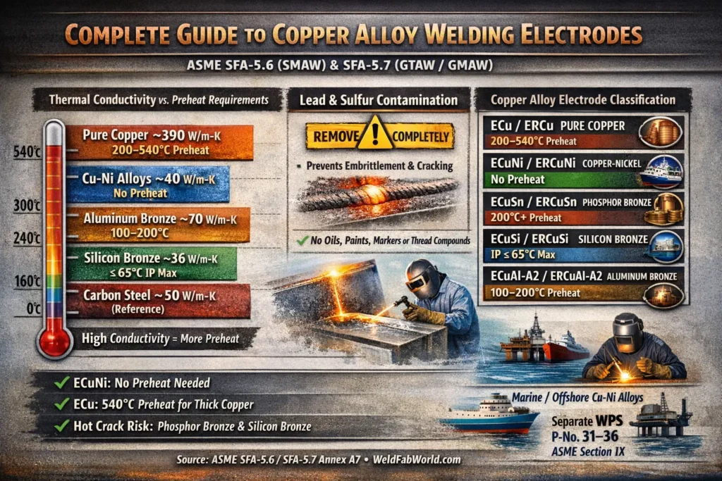
Although copper-nickel alloys are genuinely not difficult to weld, they are unforgiving of poor preparation and contamination. A single trace of lead from a marking crayon, or sulfur from a cutting lubricant, can produce catastrophic intergranular cracking in an otherwise perfect-looking weld. The applicable ASME consumable specifications — SFA-5.6 for SMAW covered electrodes and SFA-5.7 for bare wire GTAW/GMAW — contain specific Annex A7 guidance that every welding engineer and inspector working with these alloys must understand. This guide covers the complete picture: alloy grades and properties, consumable selection, joint preparation, GTAW and SMAW welding technique, contamination control, applicable offshore codes, and the qualification framework under ASME Section IX.
Whether you are writing a Welding Procedure Specification (WPS) for offshore seawater piping, qualifying a welder on Cu-Ni under ASME Section IX, or conducting a welding inspection review for an FPSO construction package, this guide provides the technical depth you need.
The Two Marine Grades — 90/10 vs 70/30 Copper-Nickel
Marine service specifies two principal copper-nickel grades. Both contain iron and manganese additions beyond the baseline copper-nickel ratio; these additions are essential for corrosion resistance in flowing seawater and must be present in both the base material and the weld filler metal to ensure the protective oxide film forms correctly across the weld.
90/10 Cu-Ni — C70600
- Composition: Cu-Ni9-10Fe1-2Mn (approx)
- UNS: C70600
- ISO: CuNi10Fe1Mn
- Tensile: ~300–380 MPa
- Thermal cond.: ~40 W/m·K
- Primary use: Seawater piping, fire mains, heat exchanger shells, offshore HVAC
- Corrosion rate: ~0.01 mm/yr (film established)
70/30 Cu-Ni — C71500
- Composition: Cu-Ni30Fe0.5-1Mn (approx)
- UNS: C71500
- ISO: CuNi30Mn1Fe
- Tensile: ~380–480 MPa
- Thermal cond.: ~29 W/m·K
- Primary use: High-velocity condenser tubes, naval vessels, desalination evaporators
- Corrosion rate: Lower than 90/10 at elevated velocity
The iron content in both grades (1–2% Fe for 90/10, 0.5–1% Fe for 70/30) is the key to seawater corrosion resistance. Iron is incorporated into the protective Cu-Ni oxide film on the pipe surface, making the film more adherent and resistant to chloride attack. The manganese additions improve hot workability and weldability. The weld filler metal (ERCuNi / ECuNi) typically contains approximately 29–32% Ni, 1.0–2.0% Fe, and 0.5–1.5% Mn to ensure the weld metal matches or exceeds the corrosion resistance of the base material at the fusion boundaries.
| Property | 90/10 Cu-Ni (C70600) | 70/30 Cu-Ni (C71500) | Carbon Steel (reference) |
|---|---|---|---|
| Nickel content (%) | 9–11 | 29–33 | Nil |
| Density (kg/m³) | 8,940 | 8,940 | 7,850 |
| Thermal conductivity (W/m·K) | ~40 | ~29 | ~50 |
| UTS (MPa, annealed) | 300–380 | 380–480 | 400–550 |
| Elongation (%, annealed) | ≥30 | ≥30 | ~22 |
| Corrosion rate — seawater (mm/yr) | 0.01 (film stable) | <0.01 | 0.1–0.5+ |
| ASME Section IX P-Number | P-33 | P-33 | P-1 |
| Preheat required (SFA-5.7) | None | None | Varies by CE |
The Corrosion Protection Mechanism — Why Cu-Ni Works in Seawater
The extraordinary performance of copper-nickel alloys in seawater is not passive in the way that chromium oxide protects stainless steel. Instead, Cu-Ni develops a multi-layer protective film over approximately three months of initial service exposure. This film consists primarily of cuprous oxide (Cu&sub2;O) as the inner layer and a mixed copper-nickel oxide/chloride outer layer. The iron incorporated from the alloy makes this film particularly compact, adherent, and resistant to both chloride ion attack and mechanical erosion under flow conditions.
Once the protective film is fully established, the corrosion rate in seawater drops from an initial ~0.1 mm/yr to approximately 0.01 mm/yr or less for 90/10 and even lower for 70/30. This predictable long-term performance — with decades of operational data from naval vessels, desalination plants, and offshore platforms — is the reason Cu-Ni remains the engineer’s material of choice for seawater systems despite its higher initial cost compared to carbon steel.
Welding Consumables — SFA-5.6 (SMAW) and SFA-5.7 (GTAW/GMAW)
ASME SFA-5.6 covers copper and copper alloy covered (SMAW) electrodes and SFA-5.7 covers bare wire electrodes and rods for GTAW, GMAW, and FCAW. Both specifications classify copper-nickel consumables under the ECuNi (covered electrode, SFA-5.6) and ERCuNi (bare wire, SFA-5.7) designations. A single consumable composition — approximately 29–32% Ni with Fe and Mn — is suitable for welding both 90/10 and 70/30 base materials, providing compatible strength and superior corrosion performance across the weld metal and heat-affected zones.
ECuNi Chemical Composition Requirements
| Element | ERCuNi (SFA-5.7) | ECuNi (SFA-5.6) | Role in Weld Metal |
|---|---|---|---|
| Copper (Cu) | Remainder | Remainder | Primary matrix, corrosion resistance |
| Nickel (Ni) + Co | 29.0–32.0% | 29.0–32.0% | Solid solution strengthening; seawater resistance |
| Iron (Fe) | 0.40–0.75% | 0.40–0.75% | Critical for protective film formation |
| Manganese (Mn) | 1.0–2.5% | 1.0–2.5% | Deoxidiser; improves fluidity and weldability |
| Titanium (Ti) | 0.20–0.50% | 0.20–0.50% | Deoxidiser; grain refiner; reduces porosity |
| Silicon (Si) | 0.25% max | 0.25% max | Deoxidiser at low levels; excess harmful |
| Lead (Pb) | 0.02% max | 0.02% max | STRICTLY LIMITED — causes intergranular cracking |
| Sulfur (S) | 0.02% max | 0.02% max | STRICTLY LIMITED — causes hot cracking |
| Carbon (C) | 0.10% max | 0.10% max | Kept low to maintain ductility |
The titanium addition in ERCuNi is particularly important for weld quality. Titanium acts as a strong deoxidiser and nitride former, effectively scavenging oxygen and nitrogen from the weld pool that would otherwise form porosity. The short arc requirement specified in SFA-5.7 A7.5.2 works in conjunction with titanium deoxidation to produce porosity-free weld metal: a short arc reduces the path length over which atmospheric contamination can enter the shielding gas envelope.
Why No Preheat? The Conductivity Explanation
Contamination Control — The Most Critical Factor in Cu-Ni Welding
No aspect of copper-nickel welding preparation is more important than contamination control. While steel welding tolerates moderate surface contamination with relatively minor consequences (porosity, reduced toughness), copper-nickel welding is catastrophically sensitive to lead and sulfur. ASME SFA-5.7 Annex A6.2 is explicit and unambiguous on this point.
Lead Embrittlement Mechanism
Lead has an extremely low solubility in solid copper (effectively zero at room temperature) and a low melting point of 327°C. When lead contamination is present on the weld preparation surface and the arc is struck, the lead melts and is swept into the weld pool. As the weld metal solidifies, lead is rejected to grain boundaries where it remains as a liquid film while the surrounding copper-nickel is already solid and contracting under thermal stress. The tensile residual stresses that develop during cooling shear these thin liquid grain boundary films apart, producing intergranular cracks. These cracks often occur internally and are not visible at the weld surface — they are discovered under hydrostatic test or radiographic examination, or worse, in service under operating pressure.
The insidious aspect of lead contamination is the source: it is almost always a common workshop material. Temperature-indicating crayons (Tempilstik), some anti-seize compounds, certain cutting oils, lead-containing paints on old pipe spools, and even some marking pens can introduce sufficient lead to cause cracking. Stencil inks and rubber stamps used for heat number identification on pipe should also be checked.
Contamination Prevention Protocol
- Degrease the entire weld preparation zone (50 mm each side) with acetone or MEK before any mechanical preparation.
- Mechanically clean with dedicated stainless steel wire brushes or grinding discs — never use tools previously used on carbon steel, as iron contamination deposits can cause porosity.
- Ensure all temperature-indicating materials are lead-free and sulfur-free. Use electronic thermometers or non-contact pyrometers where possible.
- Check all marking fluids, anti-seize compounds, and cutting lubricants for lead and sulfur content before use on Cu-Ni material.
- Store Cu-Ni pipe and fittings away from galvanised steel and lead-containing surfaces. Lead contamination can transfer by contact.
- Final wipe with clean acetone-soaked lint-free cloth immediately before tacking and welding. Do not touch the cleaned surface bare-handed (skin oils can cause porosity).
Joint Preparation for Cu-Ni Pipe Welding
Joint preparation for copper-nickel pipe welding follows broadly similar geometry to carbon steel piping, but with some Cu-Ni-specific considerations around root gap tolerances and back-purging requirements.
Standard Butt Joint Geometry
| Joint Parameter | Recommended Value | Notes |
|---|---|---|
| Bevel angle (per side) | 30°–35° | Total included angle 60°–70° |
| Root face | 0–1.5 mm | Feather edge acceptable for thin wall |
| Root gap | 2–3 mm | Consistent gap critical for root fusion |
| Cleaning zone | 50 mm each side minimum | Degrease then mechanical clean |
| Back-purge gas | Argon (99.995% pure) | Recommended for all root passes in pipe |
| Purge O&sub2; level | ≤100 ppm before welding | Monitor with oxygen analyser |
| Interpass temperature | ≤150°C (max) | Not a code limit, but good practice |
GTAW Welding Technique for Cu-Ni Pipe
Gas Tungsten Arc Welding (GTAW / TIG) is the primary process for copper-nickel pipe welding, particularly for root passes and all positions on thinner-wall pipe. The combination of precise heat input control, excellent shielding coverage, and the ability to weld in all positions makes GTAW the preferred choice for the quality-critical seawater piping joints found in offshore and naval applications. The GTAW process for Cu-Ni uses the same fundamental technique as for stainless steel, with several Cu-Ni-specific adjustments.
GTAW Parameters for Cu-Ni
| Parameter | Setting / Value | Code Basis / Notes |
|---|---|---|
| Polarity | DCEN (electrode negative) | SFA-5.7 A6.3 — standard for GTAW copper alloys |
| Tungsten electrode type | EWLa-1.5 or EWTh-2 per SFA-5.12 | Lanthanated preferred over thoriated for safety |
| Shielding gas | Pure Argon (SG-A per SFA-5.32) | O&sub2;-bearing gases not permitted (SFA-5.7 A7.1.3) |
| Shielding gas flow rate | 12–18 L/min | Higher if long arc used (avoid long arcs) |
| Arc length | As short as possible | SFA-5.7 A7.5.2 — short arc minimises porosity |
| Filler wire | ERCuNi per SFA-5.7 | Use for both 90/10 and 70/30 base metals |
| Preheat | None required | SFA-5.7 A7.5.2 — no preheat for Cu-Ni |
| Interpass temperature | ≤150°C practical limit | Allow to cool; no lower limit required |
| Travel speed | Moderate (similar to 316SS) | Avoid excessive dwell — Cu-Ni is ductile but sensitive to overheating in multiple passes |
| Welding position | All positions | SFA-5.7 A7.5.2 — ERCuNi welds all positions |
Root Pass Strategy
The root pass is the most challenging pass in Cu-Ni pipe welding. The keyhole GTAW technique or a conventional fill-and-fuse technique can be used depending on pipe diameter and wall thickness. For pipes above DN50 (2 inch), back-purging with pure argon is strongly recommended — Cu-Ni oxidises less severely than titanium but an oxidised root in a seawater pipe will be a site of preferential corrosion attack and accelerated film breakdown. The use of soluble film dams or inflatable purge bladders allows effective back-purging even on long pipe spools. See our guide on back purging equipment for pipe welding for practical equipment selection.
SMAW Welding with ECuNi Electrodes
Shielded Metal Arc Welding (SMAW) using ECuNi covered electrodes per SFA-5.6 is used for fill and cap passes on thicker pipe sections, for site repair welds, and where GTAW equipment is not available. ECuNi electrodes operate on DCEP (electrode positive) per SFA-5.6 A6.3. The technique differs from SMAW on carbon steel in several important ways:
- Slag removal: Cu-Ni weld metal produces a slag that must be thoroughly removed between passes — copper alloy slag is tenacious and will cause inclusions if not completely chipped and wire-brushed between passes.
- Bead profile: Use stringer beads rather than wide weave passes. Cu-Ni weld metal is more fluid than carbon steel and wide weaving can produce undercut and uneven bead profiles.
- Electrode size: Use 2.5 mm or 3.2 mm electrodes for the fill passes on pipe wall thicknesses up to 12 mm. Larger electrodes are used for structural and plate work.
- Electrode condition: Store ECuNi electrodes in a dry environment. Moisture pick-up by the electrode coating can cause porosity and hydrogen-related defects. Redry at 150–200°C for 1 hour if moisture exposure is suspected.
- DCEP polarity: Confirm DCEP (reverse polarity) on the welding machine before striking the arc. DCEN polarity, used for GTAW, will produce an unstable arc and poor fusion with SMAW covered electrodes.
Applicable Offshore and Marine Standards
Copper-nickel piping fabrication for offshore and naval service is governed by a hierarchy of codes and standards. The construction code prescribes design and inspection requirements; the material standards define alloy specifications; and the welding codes define procedure and welder qualification.
| Standard | Issuing Body | Scope | Applicability |
|---|---|---|---|
| EEMUA 144 | EEMUA | 90/10 Cu-Ni alloy piping — offshore applications: tubes, fittings | Offshore seawater piping |
| EEMUA 145 | EEMUA | 90/10 Cu-Ni flanges (composite and solid) for offshore | Offshore flanges |
| DEF STAN 02-781 | UK MoD | Cu-Ni piping for Royal Navy seawater systems | Naval vessels |
| ASTM B466 / B467 | ASTM | Seamless and welded Cu-Ni pipe and tube (C70600, C71500) | Material specification |
| ASTM B151 | ASTM | Cu-Ni rod, bar, and shapes for machined fittings | Material specification |
| ASME B31.3 | ASME | Process piping design, fabrication, examination | Process piping construction |
| ASME Section IX | ASME | WPS, PQR, welder qualification | Welding qualification |
| ISO 15614-6 | ISO | Specification and qualification of welding procedures — copper alloys | European/ISO projects |
| ASME SFA-5.6 | ASME/AWS | Copper and copper alloy covered (SMAW) electrodes — ECuNi | Consumable specification |
| ASME SFA-5.7 | ASME/AWS | Copper alloy bare wire (GTAW/GMAW) — ERCuNi | Consumable specification |
ASME Section IX Qualification — P-Numbers and WPS Requirements
Under ASME Section IX, copper-nickel alloys are assigned to P-Number 33 in Table QW/QB-422. This means that a Welding Procedure Specification (WPS) and supporting Procedure Qualification Record (PQR) qualified on P-33 base metal covers welding of P-33 to P-33 joints. Copper-nickel does not share a P-number with other copper alloy families — a WPS qualified on P-35 (aluminum bronze) or P-32 (silicon bronze) does not cover P-33 copper-nickel, and a separate qualification test is required.
Essential Variables for Cu-Ni WPS
When writing a WPS and conducting a PQR for Cu-Ni welding, the following are among the key essential variables that, if changed outside qualified limits, require requalification:
- P-Number: P-33 to P-33. A change to any other P-number combination requires new PQR.
- F-Number: F-37 (ERCuNi/ECuNi). A change in F-Number requires requalification.
- A-Number: A-95 (copper-nickel alloy weld metal). Change requires requalification.
- Process: GTAW qualified does not automatically cover SMAW. Each process requires its own PQR.
- Shielding gas: Gas type and composition are essential variables for GTAW — changing from pure argon to Ar/He requires requalification.
- Consumable classification: ECuNi (SFA-5.6) or ERCuNi (SFA-5.7) must be recorded accurately on the WPS.
- Position: The qualified position range per QW-461 applies.
Post-Weld Requirements and Inspection
Post-Weld Heat Treatment (PWHT)
Post-weld heat treatment is not required for 90/10 or 70/30 copper-nickel alloys under the construction codes applicable to marine and offshore service (ASME B31.3, ASME Section VIII). Cu-Ni alloys do not develop hardened microstructures, hydrogen-assisted cracking susceptibility, or the residual stress distributions that make PWHT necessary for low-alloy steels. The weld metal and HAZ retain excellent ductility and toughness in the as-welded condition across the full service temperature range from cryogenic to approximately 300°C.
For high-specification naval or nuclear applications where residual stress relief is required, a solution anneal at 700–800°C followed by water quenching may be specified in the applicable defence standard (e.g., DEF STAN 02-781). This is not a standard offshore fabrication requirement.
Non-Destructive Examination
Visual examination (VT) of all weld surfaces (root accessible bore side, weld cap) is mandatory for all classes of piping. Radiographic Testing (RT) or Ultrasonic Testing (UT) is specified for higher-risk joints per the construction code. Cu-Ni is radiographically similar to carbon steel in terms of X-ray transparency — standard radiographic techniques for pipe welds apply without significant modification. For mechanical testing of procedure qualification test pieces, tensile, bend, and macro examination are performed per ASME Section IX QW-150/160.
Magnetic Particle Testing (MT) is not applicable to copper-nickel alloys as they are non-ferromagnetic. Dye Penetrant Testing (PT) is used for surface crack detection and is fully applicable to Cu-Ni. Liquid penetrant examination is particularly useful for detecting the lead-contamination-induced hot cracks described earlier, which may appear as fine, irregular surface-connected indications on the weld surface or at the weld-HAZ interface.
Common Welding Defects in Cu-Ni and Their Causes
| Defect | Probable Cause | Prevention |
|---|---|---|
| Porosity | Long arc length, inadequate shielding gas coverage, moisture on electrode or joint | Shorten arc; check gas flow; degrease; redry electrodes |
| Intergranular hot cracking | Lead or sulfur contamination from surface materials | Rigorous contamination removal per SFA-5.7 A6.2 |
| Lack of fusion | Insufficient heat input; oxide film on joint face not removed | Mechanical clean bevel faces; increase current; use correct process |
| Root concavity / suck-back | Excessive root gap, over-penetration, arc blow | Control root gap; reduce current; use DCEN; back-purge |
| Oxidised root / black root | Insufficient or absent back-purge; O&sub2; level too high during welding | Back-purge with argon; verify O&sub2; ≤100 ppm before welding |
| Undercut | Excessive weave; high travel speed at bevel face | Use stringer beads; reduce travel speed at edges |
| Slag inclusions (SMAW) | Incomplete slag removal between passes | Chip and wire-brush thoroughly between every pass |