NDT Method Selection Guide: RT vs UT vs MT vs PT vs ECT
Choosing the right non-destructive testing method is one of the most consequential decisions a welding engineer or QA/QC inspector makes on any fabrication job. Radiographic testing (RT), ultrasonic testing (UT), magnetic particle testing (MT), liquid penetrant testing (PT), and eddy current testing (ECT) each detect a different subset of defects, work on a different range of materials, and carry very different cost and schedule implications. Pick the wrong method and you either miss a rejectable defect or spend money and time inspecting for flaws that were never a real risk on that joint.
This guide consolidates the individual method references on WeldFabWorld into a single decision framework. Instead of reading five separate articles to figure out which method applies to your weld, material, and code, use the matrix and flowchart below to get to the right answer directly, then follow the links through to the full method-specific guide for procedure and acceptance criteria detail.
Scope note: This article covers method selection logic for welds and wrought materials in typical fabrication and piping/pressure-vessel work. It does not replace your project-specific inspection and test plan (ITP), client specification, or the applicable construction code, all of which take precedence over the general guidance here.
Quick Decision Matrix
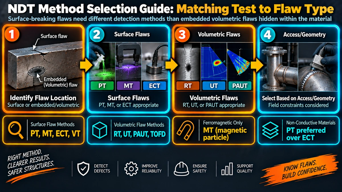
Use this matrix as a first-pass filter. Cross-reference defect location (surface vs subsurface vs volumetric), material type, and section thickness against the five methods before committing to a procedure.
| Criterion | RT | UT | MT | PT | ECT |
|---|---|---|---|---|---|
| Defect location | Volumetric | Volumetric | Surface / near-surface | Surface only | Surface / near-surface |
| Material requirement | Any | Any (dense, elastic) | Ferromagnetic only | Any non-porous | Conductive only |
| Best defect type | Porosity, slag, volumetric voids | Lack of fusion, cracks, laminations | Surface cracks, laps | Fine surface cracks, porosity | Tube/tube-sheet cracking, thinning |
| Typical thickness range | Up to ~300 mm (source-dependent) | 3 mm to several metres | No practical limit (surface only) | No practical limit (surface only) | Thin wall, tubing, coatings |
| Permanent record | Yes (film/digital) | Optional (data logger) | No | No | Optional (trace) |
| Relative cost per joint | High | Medium | Low | Low | Medium |
| Radiation safety controls | Required | None | None | None | None |
| Primary code reference | ASME BPVC Section V Article 2 | ASME BPVC Section V Article 4/5 | ASME BPVC Section V Article 7 | ASME BPVC Section V Article 6 | ASME BPVC Section V Article 8 |
Method-by-Method Overview
Radiographic Testing (RT)
RT passes X-ray or gamma radiation through the component and records the transmitted intensity on film or a digital detector. Denser regions and sound metal absorb more radiation and appear lighter; voids, porosity, and slag absorb less and appear as dark indications on the resulting radiograph. Because the image is a projection through the full thickness, RT excels at detecting volumetric defects such as porosity, slag inclusions, and internal voids, and it produces a permanent, third-party-reviewable record that many client specifications explicitly require.
RT is weaker at detecting tight planar defects such as lack of fusion or fine cracks when their plane is not aligned favourably with the beam direction, which is why UT has increasingly displaced RT on mechanized pipeline welding where lack of fusion is the dominant concern. RT also requires radiation safety exclusion zones, licensed operators, and source or generator logistics, all of which add cost and schedule compared to the other four methods.
Ultrasonic Testing (UT)
UT sends high-frequency sound waves into the material and analyses the reflected energy from internal discontinuities and back-wall surfaces. Conventional pulse-echo UT and modern phased array UT (PAUT) are both highly effective at sizing planar defects like lack of fusion, lack of penetration, and cracking, and can be applied to a far greater thickness range than RT with no radiation safety burden. UT is also faster on a per-joint basis once procedures are qualified, and time-of-flight diffraction (TOFD) adds precise through-wall sizing for fracture-critical applications.
The trade-off is that UT results are interpretation-dependent on operator skill and probe/procedure qualification, and unlike a radiograph, a conventional A-scan trace is not as intuitive for a non-specialist reviewer, though phased array sectorial views have narrowed this gap considerably.
Magnetic Particle Testing (MT)
MT magnetizes a ferromagnetic component and applies fine iron particles that cluster at leakage fields created by surface and near-surface discontinuities, making them visible under white light or UV-A illumination with fluorescent media. MT is fast, inexpensive, and effective for detecting surface cracks, laps, and cold shuts, which makes it a standard requirement on carbon and low-alloy steel weld toes and heat-affected zones.
MT is restricted to ferromagnetic materials, so it cannot be used on austenitic stainless steel, most nickel alloys, or aluminum. Yoke placement and current selection must be controlled to avoid missing defects oriented parallel to the magnetic field, which is why two orthogonal field directions are normally applied during a single inspection.
Liquid Penetrant Testing (PT)
PT relies on capillary action: a low-viscosity penetrant is applied to a clean surface, allowed to dwell and seep into surface-breaking discontinuities, then removed from the surface and drawn back out by a developer that creates a visible bleed-out indication. PT works on any non-porous material regardless of magnetic properties, making it the default surface method for stainless steels, aluminum, and other non-ferromagnetic alloys, and it is also commonly used as a lower-cost alternative to MT on carbon steel when magnetization equipment is impractical.
PT only detects defects that are open to the surface, requires adequate dwell time that cannot be rushed without losing sensitivity, and is sensitive to surface condition, since coatings, scale, or excessive surface roughness can mask indications or produce false positives.
Eddy Current Testing (ECT)
ECT induces alternating eddy currents in a conductive material through a coil and measures how surface and near-surface discontinuities, wall loss, and conductivity changes disturb those currents. It is widely used for heat exchanger and condenser tube inspection, weld toe cracking surveys, and coating thickness measurement, and it requires no consumables or dwell time, which makes it very fast for repetitive inspection of tubing and thin sections.
ECT is limited to conductive materials, its penetration depth is limited by the skin effect at the frequency selected, and interpretation requires careful calibration against reference standards to separate genuine defect signals from geometric and material-property noise.
Defect Type vs Recommended Method
| Defect type | Location | Recommended method | Secondary option |
|---|---|---|---|
| Porosity | Volumetric | RT | UT |
| Slag inclusion | Volumetric | RT | UT |
| Lack of fusion | Volumetric / planar | UT (PAUT) | RT |
| Lack of penetration | Volumetric / planar | UT | RT |
| Root/toe crack | Surface | MT (ferromagnetic) / PT (non-magnetic) | ECT (thin section) |
| Undercut | Surface | Visual testing (VT) | MT / PT confirmation |
| Laminations in plate | Volumetric | UT | RT |
| Tube wall thinning / corrosion | Volumetric, thin section | ECT / UT thickness gauging | RT (limited) |
Code note: ASME BPVC Section V provides the general methodology for each technique (Article 2 for RT, Article 4/5 for UT, Article 6 for PT, Article 7 for MT, Article 8 for ECT), while acceptance criteria come from the construction code, such as ASME Section VIII Division 1 or B31.3. Always confirm the governing code combination before finalizing a procedure, and cross-check the required mechanical testing package where NDT alone will not satisfy welding procedure qualification.
Worked Example: Selecting a Method for a Pipeline Girth Weld
Consider a mechanized GMAW girth weld on 12 mm wall carbon steel line pipe, where the dominant concern from process control data is intermittent lack of fusion at the hot pass to fill pass interface, and site access limits radiation exclusion zones during a live tie-in.
Practical tip: When mechanized welding data shows a recurring lack-of-fusion signature, favour UT over RT even where radiography access exists, since UT sizing accuracy for planar defects generally outperforms RT unless the defect happens to align favourably with the beam.
Caution: Do not substitute PT for MT on ferromagnetic base metal purely for convenience. MT detects some shallow subsurface indications that PT will miss entirely, since PT only responds to defects open to the surface.
Cost, Speed, and Practical Considerations
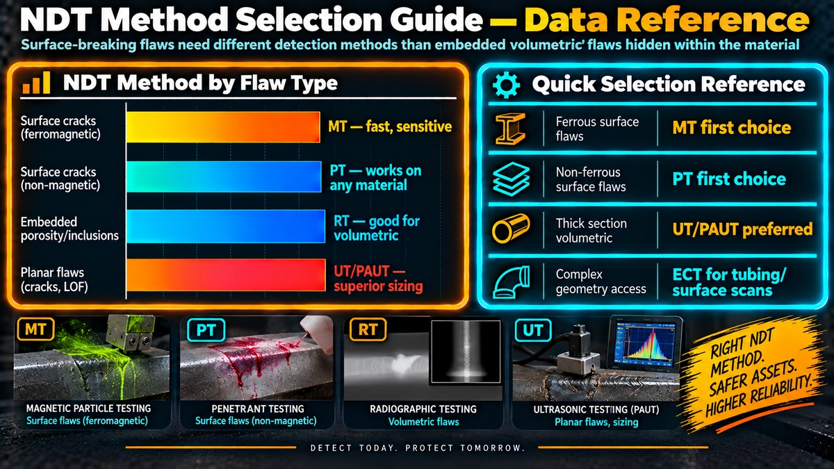
| Factor | RT | UT | MT | PT | ECT |
|---|---|---|---|---|---|
| Setup time | High (safety controls) | Low-Medium | Low | Low | Low |
| Result turnaround | Hours (film processing) | Immediate | Immediate | 15-60 min (dwell time) | Immediate |
| Operator skill dependency | Medium | High | Low-Medium | Low-Medium | High |
| Repeatability for production QC | Medium | High | High | Medium | High |
For high-volume repetitive production inspection, such as pipeline mainline welding or pressure vessel nozzle welds, the combination of UT for volumetric coverage and MT or PT for surface coverage generally gives the best balance of cost, schedule, and defect coverage. RT remains the right choice where the client specification mandates a permanent radiographic record, where UT access is geometrically restricted, or where the code explicitly requires radiography, such as certain P-Number combinations and thickness ranges under specific construction codes.
Recommended Reference Books
ASME BPVC Section V — Nondestructive Examination
The primary code reference for RT, UT, MT, PT, and ECT methodology, essential for any inspector writing or reviewing NDT procedures.
View on AmazonHandbook of Nondestructive Evaluation
A practical reference covering the physical principles behind each NDT method with application-focused examples for welded fabrication.
View on AmazonUltrasonic Testing Level II Study Guide
Focused preparation material for UT certification, covering phased array basics, calibration, and defect sizing techniques used in weld inspection.
View on AmazonRadiographic Interpretation for Welded Joints
A visual reference for identifying porosity, slag, lack of fusion, and cracking signatures on production and reference radiographs.
View on AmazonDisclosure: WeldFabWorld participates in the Amazon Associates programme (StoreID: neha0fe8-21). If you purchase through these links, we may earn a small commission at no extra cost to you. This helps support free technical content on this site.
Frequently Asked Questions
Which NDT method finds internal weld defects best?
Radiographic testing (RT) and ultrasonic testing (UT) are the two volumetric methods capable of detecting internal defects such as porosity, slag, lack of fusion, and internal cracking. RT gives a permanent film or digital image that is easy for third parties to review, while UT is faster, safer, and better at detecting planar defects like lack of fusion and cracks. See our full ultrasonic testing guide for procedure detail.
Can magnetic particle testing be used on stainless steel?
Magnetic particle testing (MT) only works on ferromagnetic materials, so it cannot be used on austenitic stainless steel, aluminum, or other non-magnetic alloys. For those materials, liquid penetrant testing (PT) or eddy current testing (ECT) is used instead to find surface-breaking defects.
Why choose PT over MT for surface defect detection?
Liquid penetrant testing works on any non-porous material, magnetic or not, which makes it the default choice for stainless steels, aluminum, and other non-ferromagnetic alloys. Magnetic particle testing is preferred on carbon and low-alloy steels because it is faster, does not require dwell time for penetrant to seep into defects, and can also detect some shallow subsurface indications that PT would miss.
Is eddy current testing a replacement for ultrasonic testing?
No. Eddy current testing (ECT) is primarily a surface and near-surface method for conductive materials and is widely used for tube inspection, weld toe cracking, and coating thickness checks. It cannot reliably detect deep internal defects the way ultrasonic testing can, so the two methods serve different roles rather than substituting for each other.
What NDT method is required by ASME Section IX for welder qualification?
ASME Section IX itself does not mandate a specific NDT method for welder performance qualification; it typically requires either radiography or mechanical bend testing of the test coupon, per QW-191 and QW-160. Production welds are then inspected per the applicable construction code, such as ASME Section VIII Division 1 or B31.3, which specify the required NDT methods and acceptance criteria. Test your knowledge with our ASME Section IX quiz.
How do I choose between RT and UT for a pipeline girth weld?
For pipeline girth welds, UT is increasingly preferred over RT because it does not require radiation safety exclusion zones, gives faster turnaround, and is highly effective at sizing planar defects like lack of fusion, which is a common concern in mechanized GMAW pipeline welding. RT remains useful where a permanent visual record is required or where UT access is restricted by geometry.
Does NDT method selection affect welding procedure qualification cost?
Yes. The NDT methods specified in a welding procedure specification directly affect inspection cost and schedule, since RT typically costs more per joint and takes longer to process than UT or MT, while PT is comparatively inexpensive but limited to surface indications. Selecting the leanest method that still satisfies the applicable code and service conditions helps control overall fabrication cost.
Can more than one NDT method be required on the same weld?
Yes, many codes and client specifications require combined methods, such as UT or RT for volumetric coverage plus MT or PT for surface coverage on the same joint, especially on critical service welds like sour service piping or pressure vessel nozzles. Combining a volumetric and a surface method gives more complete defect coverage than either method alone.