Metallography Sample Preparation for Weld Examination
Metallography sample preparation for weld examination is where most bad micrographs actually go wrong — not in the etching, and not in the microscope, but several steps earlier in grinding and polishing, where a rushed stage or the wrong etchant choice for the alloy in question quietly ruins a specimen before anyone looks at it under magnification. Getting a clean, artifact-free, representative surface is a skill in its own right, and it becomes considerably harder the moment the specimen is a dissimilar metal weld, a duplex stainless steel, or a section destined for SEM or EBSD rather than an optical microscope.
This guide assumes familiarity with the basic macro/micro examination process and goes deeper into the parts that cause the most practical difficulty: recognising and fixing common preparation artifacts, selecting the right etchant for the alloy actually in front of you, preparing dissimilar metal welds with dual etching, additional requirements for SEM and EBSD work, and quantitative grain size measurement. For the foundational process — specimen selection, standard grinding/polishing sequence, and code acceptance criteria — see the macro vs micro tests in welding guide, which this article builds on rather than repeats.
Preparation Artifacts and How to Fix Them
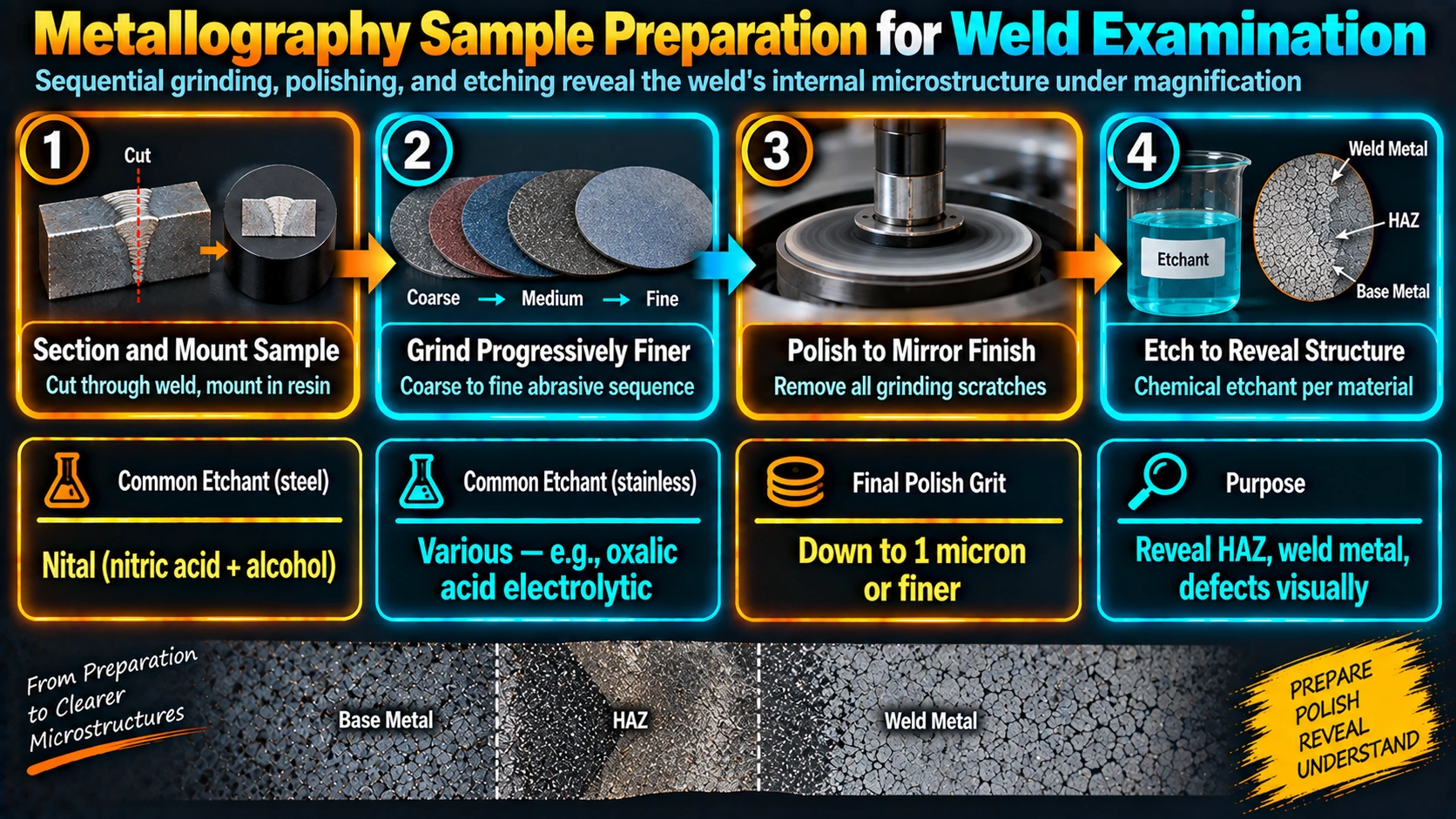
Most poor-quality weld micrographs trace back to a specific, recognisable preparation artifact rather than a genuine microstructural feature. Learning to recognise these on sight saves significant repreparation time.
| Artifact | Typical Cause | Fix |
|---|---|---|
| Comet tails / pull-out | Hard inclusion or particle dislodged, abrasive drags across the cavity | Lighter pressure, shorter stage times, adequate lubrication |
| Relief (rounding at phase boundaries) | Differential polishing rate between phases of different hardness | Harder final-stage cloth, shorter polish time, vibratory/colloidal silica finishing |
| Residual scratches after etch | Coarser-grit scratches not fully removed before moving to finer grit | Systematic grit progression, rotate 90 degrees between stages, verify removal before advancing |
| Embedded abrasive particles | Soft matrix embedding SiC or diamond particles during grinding | Thorough ultrasonic cleaning between stages, appropriate lubricant selection |
| Etch pitting / staining | Etchant concentration too strong, or etch time too long for the alloy | Dilute etchant, shorter controlled etch time, re-polish and re-etch |
| False deformation twins (austenitic alloys) | Excessive mechanical pressure during grinding/polishing inducing twinning | Reduce pressure, use electrolytic polishing as final stage for soft austenitic alloys |
Alloy-Specific Etchant Selection
The etchant that reveals a clean, contrast-rich microstructure on carbon steel will often show nothing useful — or actively mislead — on austenitic stainless, duplex, or nickel-base weld metal, because these etchants rely on differential chemical attack that is specific to the phases actually present in each alloy family.
| Material | Common Etchant | Reveals |
|---|---|---|
| Carbon / low-alloy steel | Nital (2-5% HNO3 in ethanol), Picral | Ferrite, pearlite, martensite, general HAZ structure |
| Austenitic stainless steel | Kalling’s No. 2, electrolytic oxalic acid (10%) | Grain boundaries, carbide precipitation, sensitization |
| Duplex / super duplex stainless | Beraha’s reagent, electrolytic 40% NaOH | Ferrite/austenite phase contrast and balance |
| Nickel-base alloys (Inconel, Monel) | Kalling’s No. 2, electrolytic chromic acid, aqua regia-based reagents | Grain structure, carbide/precipitate distribution |
| Duplex stainless / dissimilar joints (ferrite quantification) | Electrolytic etch combined with point-count or magnetic method | Ferrite number / percentage per delta ferrite guide |
Dissimilar Metal Welds: Dual (Sequential) Etching
Dissimilar metal welds — a low-alloy steel welded to a nickel-base alloy is a common example — present a specific challenge: a single etchant almost never reveals both sides of the joint clearly, because each base metal and the weld deposit itself typically require a different etching chemistry. A widely used approach is dual, sequential etching on the same polished section:
- Cold mount the specimen in epoxy resin to avoid any heat-affected artifact from hot mounting.
- Grind progressively on silicon carbide paper through the standard grit sequence.
- Polish with diamond suspensions down to a 1 micron finish.
- Etch the ferritic/low-alloy steel side first with a reagent such as dilute nital, leaving the nickel alloy side largely unaffected by this step.
- Separately etch the nickel alloy weld side using an electrolytic reagent (such as a chromic acid solution under a controlled applied potential), which does not disturb the already-revealed ferritic side.
This sequential technique reveals usable microstructure across both dissimilar regions on a single polished section, which a single universal etchant cannot achieve. See the P91 welding guide and duplex stainless steels guide for the alloy-specific metallurgical context behind why these joints are prepared this way.
Preparation for SEM and EBSD Examination
Optical metallography preparation is usually not sufficient on its own for scanning electron microscope (SEM) or electron backscatter diffraction (EBSD) work. SEM imaging typically benefits from a finer final polish — often finishing with colloidal silica rather than stopping at 1 micron diamond — to remove the shallow deformation layer that can otherwise obscure fine sub-micron features under electron imaging. Non-conductive phases or mounting media may require a thin conductive coating (carbon or gold-palladium) to prevent charging artifacts. EBSD work is more demanding still, since the technique is highly sensitive to residual surface deformation from mechanical polishing — an additional vibratory polishing stage or ion milling step is generally required to produce a surface suitable for reliable diffraction pattern collection.
Quantitative Metallography
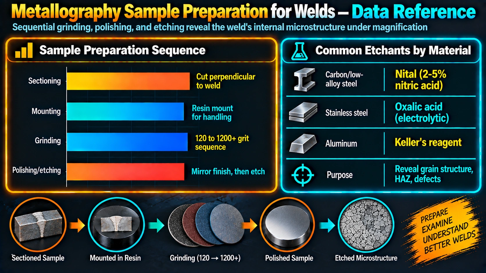
Grain Size Measurement (ASTM E112)
ASTM E112 provides standardized methods — primarily the intercept method and the planimetric (Jeffries) method — for measuring average grain size from a properly prepared and etched specimen, expressed as an ASTM grain size number. In weld examination, this is used to quantify HAZ grain coarsening, compare grain size across different welding heat input levels, and support correlation with measured hardness or Charpy toughness results from the same joint — see the toughness vs hardness guide for that correlation in context.
Ferrite Content Measurement
Ferrite number or percentage in duplex and austenitic stainless weld metal is quantified either by magnetic (Ferritescope) methods or by manual point-count on a properly etched and contrast-revealing metallographic section per ASTM E562, both of which depend entirely on a preparation and etch quality that clearly distinguishes ferrite from austenite.
Field and Replication Metallography
When a sample cannot be destructively removed from equipment that must remain in service, in-situ replication metallography provides an alternative: the surface area of interest is ground and polished directly on the component, often using portable electrolytic polishing equipment, then etched, and a thin acetate or plastic replica film is pressed onto the prepared surface to lift a negative impression of the microstructure for laboratory examination. This technique is generally limited to surface and near-surface features rather than full through-thickness examination, but it is a valuable tool for in-service creep damage assessment, weld HAZ condition monitoring, and other situations where cutting a sample is not an option.
Frequently Asked Questions
What causes comet-tail or pull-out marks during grinding and polishing of weld specimens?
Comet tails and pull-out typically occur when a hard inclusion or second-phase particle is dislodged from a softer matrix during grinding or polishing, and the abrasive then drags across the resulting cavity, leaving a trailing scratch mark. This is common in weld metal containing slag inclusions, hard carbides, or in dissimilar metal welds where a much harder phase sits in a softer matrix, and is generally reduced by using lighter polishing pressure, shorter polishing times per stage, and progressively finer abrasive with adequate lubrication rather than trying to force through the defect quickly with heavier pressure.
Why does relief (rounding at phase boundaries) occur and how is it prevented?
Relief occurs when phases or constituents of different hardness polish at different rates, causing the softer phase to be removed slightly faster than the harder phase and leaving a stepped or rounded surface rather than a flat one — a particular problem in duplex stainless steel and dissimilar metal welds where ferrite, austenite, and weld metal phases can have meaningfully different hardness. Using a harder polishing cloth for the final stages, reducing polishing time, and using vibratory or colloidal silica final polishing rather than extended mechanical polishing all help minimise relief in mixed-hardness microstructures.
Why do austenitic stainless steel and nickel alloy welds require different etchants than carbon steel?
Nital and picral, the standard etchants for carbon and low-alloy steel, rely on differential attack of ferrite, pearlite, and martensite phases that simply are not present in the same form in austenitic stainless or nickel-base weld metal, which is predominantly austenitic and highly alloyed with chromium, nickel, and molybdenum. Etchants such as Kalling’s reagent, electrolytic oxalic acid, or Vilella’s reagent are formulated specifically to reveal grain boundaries and carbide precipitation in these austenitic and nickel-rich structures, and using a carbon-steel etchant on them typically produces little to no useful contrast.
How is a dissimilar metal weld between carbon steel and a nickel alloy typically prepared for metallography?
A common approach uses cold mounting in epoxy resin, progressive grinding on silicon carbide paper down to a fine grit, and diamond polishing down to 1 micron, followed by a dual (sequential) etching procedure: the ferritic low-alloy steel side is etched first with a reagent such as dilute nital, then the nickel alloy weld side — which is largely unaffected by the first etch — is separately etched with an electrolytic reagent such as chromic acid solution under a controlled applied potential. This sequential approach reveals the microstructure of both dissimilar sides on the same polished section without one etchant compromising the other region.
What additional preparation steps does SEM examination of a weld specimen require beyond standard optical metallography?
SEM examination generally requires a finer final polish, often finishing with colloidal silica rather than stopping at 1 micron diamond, to remove the fine deformation layer that can obscure sub-micron features under electron imaging. Non-conductive constituents or mounting media may also require a thin conductive coating (carbon or gold-palladium) to prevent charging artifacts during imaging, and electron backscatter diffraction (EBSD) work typically requires an additional, even finer surface preparation stage — often vibratory polishing or ion milling — to remove the residual deformation that standard mechanical polishing leaves behind.
What is ASTM E112 used for in weld metallography?
ASTM E112 provides standardized methods — primarily the intercept method and the planimetric (Jeffries) method — for measuring average grain size from a prepared and etched metallographic specimen, expressed as an ASTM grain size number. In weld examination, grain size measurement per E112 is used to quantify HAZ grain coarsening, compare grain size across different heat input welding procedures, and support correlation between measured grain size and toughness or hardness results from the same joint.
Can metallography be performed on equipment in service without cutting out a sample?
Yes, through in-situ replication metallography, where the surface area of interest is ground and polished directly on the component (often using portable electrolytic polishing equipment), etched, and then a thin acetate or plastic replica film is pressed onto the prepared surface to pick up a negative impression of the microstructure. The replica is then examined under a microscope in the laboratory, avoiding the need to remove a destructive sample from equipment that must remain in service, though the technique is generally limited to surface and near-surface features rather than full through-thickness examination.
What is the most common mistake that ruins an otherwise well-prepared weld metallography specimen?
Skipping or rushing intermediate grinding stages is one of the most common causes of a ruined specimen, since scratches from a coarser grit that are not fully removed before moving to a finer grit remain visible (and sometimes become deeper-looking) after etching, no matter how carefully the final polishing stage is performed. A consistent, systematic progression through each grit stage, with adequate time and a direction change between stages to reveal when the previous scratch pattern has been fully removed, prevents this far more reliably than trying to compensate with a longer final polish.
Recommended Reading
Metallography of Welds — ASM Handbook Vol. 9
Comprehensive reference on metallographic preparation, etching, and interpretation of weld microstructures across steel, stainless, and nickel alloys.
View on AmazonMetallographic and Materialographic Specimen Preparation (Struers)
Practical, technique-focused guide to grinding, polishing, and etching for a wide range of alloy systems.
View on AmazonMetals Handbook Desk Edition
Reference-grade coverage of etchant formulations, preparation methods, and microstructure interpretation.
View on AmazonWelding Metallurgy (Kou)
Foundational reference on weld microstructure formation, useful context for interpreting what a well-prepared micrograph is actually showing.
View on AmazonDisclosure: WeldFabWorld participates in the Amazon Associates programme (StoreID: neha0fe8-21). If you purchase through these links, we may earn a small commission at no extra cost to you. This helps support free technical content on this site.