Corrosion Under Insulation (CUI): Causes and Mitigation
Corrosion under insulation (CUI) is corrosion that hides by design — the insulation and jacketing that protect a pipe or vessel thermally also conceal the metal surface from routine visual inspection, so CUI is frequently discovered only when insulation is deliberately removed for a scheduled check, or worse, when a leak forces the issue. It is consistently ranked among the most costly and hardest-to-manage damage mechanisms in refining, petrochemical, and offshore process plants, precisely because the very insulation system that makes a plant energy-efficient is the same system that creates the trapped, cyclic-moisture environment CUI needs.
This guide covers the CUI mechanism for both carbon steel and stainless steel, the temperature windows that define real risk, the specific locations on insulated equipment where CUI concentrates, weld and fabrication-related contributing factors, and the coating, design, and inspection strategies used to manage it. For the closely related mechanisms this article builds on, see the crevice corrosion guide and the stress corrosion cracking guide.
Why CUI Happens: The Moisture Trap Mechanism
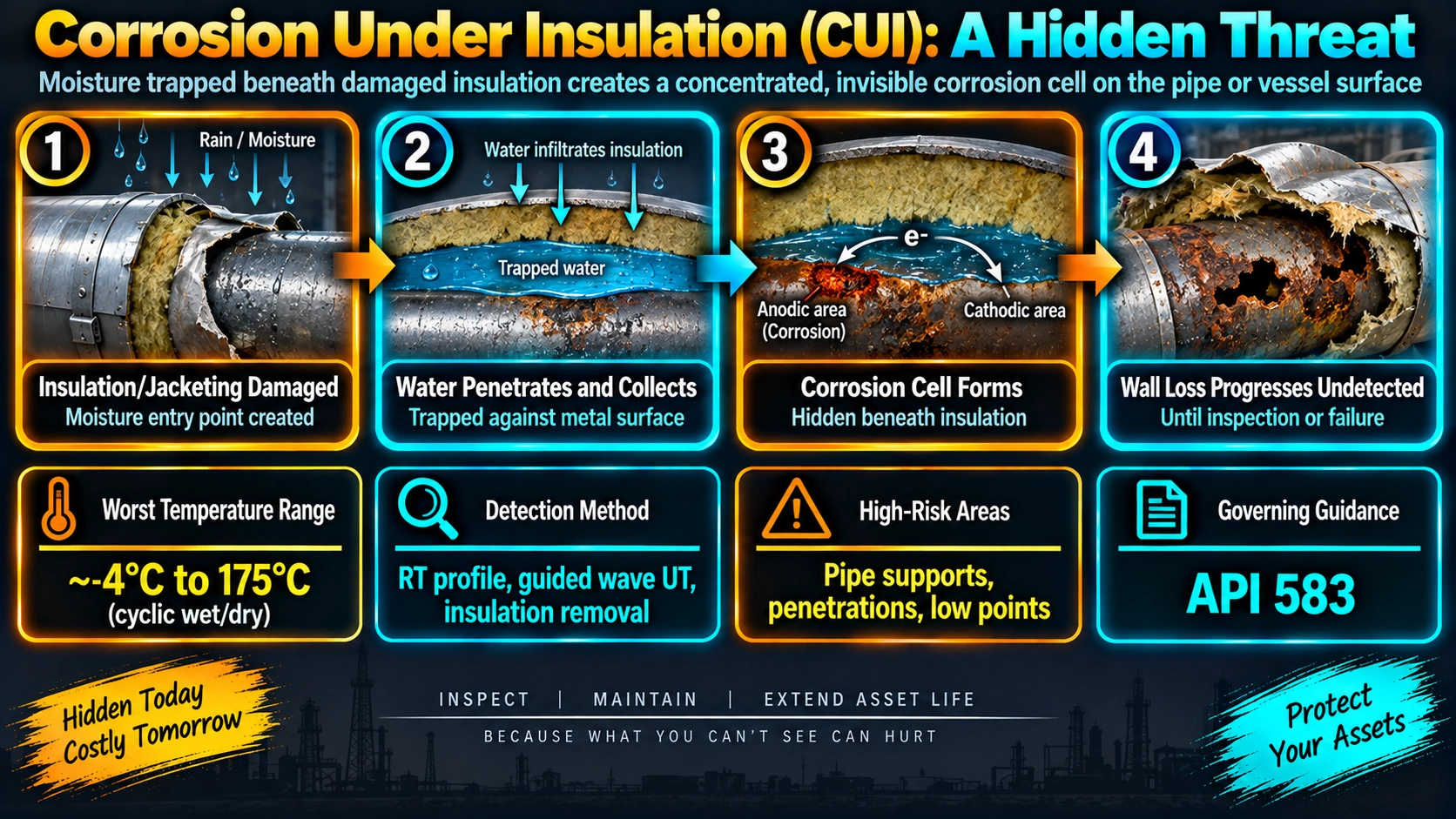
Insulation systems are not waterproof by design — they are thermally efficient, and many common insulation materials (mineral wool, calcium silicate, some foam systems) can absorb and retain moisture that enters through damaged jacketing, poorly sealed penetrations, or simple weathering over years of service. Once water is inside the insulation system, it sits in direct, prolonged contact with the metal surface, largely undisturbed by the flushing and evaporation that would occur on an uninsulated, freely exposed surface in the open air.
Thermal cycling — equipment heating up during operation and cooling during shutdowns, or simply cycling with ambient day-night temperature swings — repeatedly drives this trapped water through evaporation and condensation cycles. Each cycle concentrates dissolved chlorides, sulfates, and other corrosive species left behind as the water partially evaporates, producing a progressively more aggressive local solution against the metal surface, in much the same self-concentrating way a crevice does.
Temperature Windows That Matter
| Material | CUI Mechanism | Approx. Risk Temperature Range |
|---|---|---|
| Carbon / low-alloy steel | General and pitting corrosion | -12 to 177 degC (10-350 degF) |
| Austenitic stainless steel (304, 316) | External chloride SCC (ESCC) | 60 to 204 degC (140-400 degF) |
| Duplex / super duplex stainless | External chloride SCC (ESCC), higher CCT gives more margin | Similar window, generally more resistant per CCT ranking |
High-Risk Locations
| Location | Why It’s High Risk |
|---|---|
| Insulation terminations (flanges, valves, nozzles) | Jacketing seal is most likely to fail exactly where insulation ends |
| Pipe supports and clips | Insulation is compressed or interrupted, creating both a crevice and a water entry point |
| Low points, dead legs, sagging insulation | Water collects and stays in prolonged contact with the metal surface |
| Vertical runs with horizontal jacketing seams | Seams collect rather than shed water, unlike properly lapped vertical seams |
| Field weld locations on jacketing (“weld packs”) | Field-applied insulation closures at pipeline weld joints are a documented recurring CUI initiation point |
| Areas of prior coating damage | See the coating defects guide for how coating holidays accelerate CUI at the defect site |
Weld and Fabrication-Related Considerations
CUI risk is not purely an insulation and jacketing problem — fabrication details influence it directly. Field weld joints on piping require a matching field-applied insulation closure (sometimes called a “weld pack”), and these closures are a well-documented recurring source of CUI because they are installed under less controlled conditions than shop-applied insulation and are more prone to incomplete sealing. Coating condition at and around weld HAZs also matters: heat from welding can locally damage adjacent coating, and if that damaged area is not properly repaired before insulation is applied, it becomes a coating-defect-driven CUI initiation point exactly at the weld.
Coating and Material Strategies
| Strategy | Notes |
|---|---|
| Epoxy phenolic coating systems | Common mid-temperature CUI coating choice; verify manufacturer temperature limits against actual operating range |
| Thermal spray aluminum (TSA) | Barrier plus sacrificial protection; tolerates higher service temperature than most organic coatings; increasingly specified for high-consequence CUI-critical equipment |
| Hot-dip galvanizing | Sacrificial protection for lower-temperature applications within the zinc coating’s service limit |
| Stainless steel jacketing (vs. aluminum) | More weather and mechanical damage resistant than aluminum jacketing, reducing water ingress risk over time |
| Removable insulation covers/blankets | Used at flanges, valves, and known inspection points to allow repeated access without degrading the seal each time |
Inspection and Detection Strategies
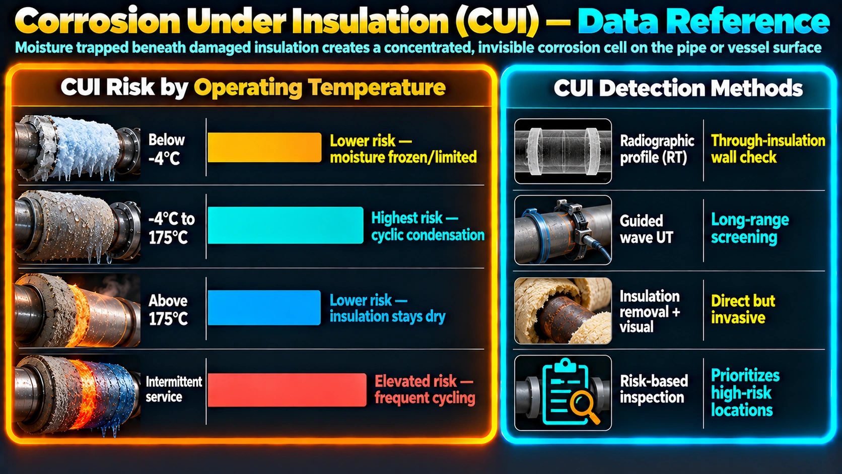
- Risk-based inspection (RBI) per API RP 571 — prioritises inspection effort by combining temperature window, insulation type, service cyclicity, coating condition, and known high-risk geometric locations rather than inspecting uniformly across all insulated equipment.
- Infrared thermography — identifies wet insulation from the surface without removal, since wet insulation has a different thermal signature than dry insulation.
- Guided wave / long range ultrasonic testing (LRUT) — screens long straight pipe runs for general wall thinning and localized metal loss; see the LRUT guide for how this technique is applied to CUI screening specifically.
- Real-time or profile radiography — checks wall condition through the insulation at specific suspect points without full removal.
- Scheduled insulation removal with direct visual and UT inspection — remains the definitive method at the highest-risk locations identified by the screening techniques above.
Frequently Asked Questions
What temperature range is most susceptible to corrosion under insulation?
For carbon and low-alloy steel, the classic CUI temperature window is approximately -12 to 177 degC (10 to 350 degF), with the highest risk typically cited around 60-120 degC where water can be present as liquid long enough to drive corrosion but the equipment still operates hot enough for repeated wet-dry cycling to concentrate corrosive species. For austenitic and duplex stainless steel, the relevant window for external chloride stress corrosion cracking is roughly 60-204 degC (140-400 degF). Equipment operating continuously well above or below these windows carries meaningfully lower CUI risk, all else equal.
Why is intermittent service equipment often at higher CUI risk than continuously hot equipment?
Equipment that cycles between hot operating temperature and ambient temperature during shutdowns or idle periods experiences repeated moisture condensation and evaporation cycles within the insulation, which concentrates chlorides and other corrosive species at the metal surface each time the water partially evaporates. Continuously hot equipment, by contrast, tends to keep any moisture that does enter in a more stable state, and equipment that stays well above the boiling point of water may simply flash off intruding moisture before it can sit against the surface for long, which is why intermittent and cyclic service is flagged as a specific CUI risk factor in inspection planning.
Does stainless steel need to be protected from CUI even though it is corrosion resistant?
Yes. Austenitic and duplex stainless steel are not immune to CUI — they are susceptible to external chloride stress corrosion cracking (ESCC) under insulation, driven by chlorides that leach from certain insulation materials, from atmospheric deposition, or from the local environment, concentrating at the metal surface through the same wet-dry cycling mechanism that drives general CUI in carbon steel. Because SCC can produce fine cracking with little visible surface corrosion, CUI-related ESCC in stainless steel is often harder to detect during inspection than the more visually obvious general corrosion typical of carbon steel. See the stress corrosion cracking guide for the underlying mechanism.
What are the highest-risk locations for CUI on an insulated pipe or vessel?
The highest-risk locations are insulation terminations and penetrations (where insulation ends at a flange, valve, or nozzle and the jacketing seal is most likely to fail), pipe supports and clips where the insulation is compressed or interrupted, low points and dead legs where water can pool inside the insulation system, and any location where jacketing overlaps or seams are not properly sealed against rain or washdown ingress. Vertical runs with horizontal jacketing seams are also higher risk because those seams act as direct water collection points rather than shedding water downward.
Can a coating alone prevent corrosion under insulation?
A properly selected and applied coating system significantly reduces CUI risk but is not a complete solution by itself, since coating failures (holidays, damage during installation, degradation over time) will still allow localized attack at the failure point, sometimes at an accelerated rate due to the area ratio effect between a small coating defect and the surrounding intact coating. Effective CUI mitigation combines coating selection (such as epoxy phenolic systems or thermal spray aluminum for higher-risk cases) with insulation and jacketing design, drainage detailing, and a scheduled inspection program rather than relying on coating performance alone.
What is thermal spray aluminum and why is it used for CUI-critical equipment?
Thermal spray aluminum (TSA) is a coating applied by thermally spraying molten aluminum onto a prepared steel surface, forming both a barrier layer and a degree of galvanic (sacrificial) protection similar to hot-dip galvanizing, but capable of withstanding higher service temperatures than most organic coatings. It is increasingly specified for high-consequence, high-temperature CUI-prone equipment — particularly in offshore and high-value onshore process plant applications — because it resists the temperature limitations that restrict many conventional coating systems in the CUI-critical range.
How is corrosion under insulation typically detected without removing all the insulation?
Common screening techniques include infrared thermography, which can identify wet insulation from the surface (wet insulation shows a different thermal signature than dry insulation) without removal, guided wave / long range ultrasonic testing (LRUT) for screening long straight pipe runs, and real-time or profile radiography through the insulation at specific points. None of these fully replace direct visual inspection, so a risk-based inspection program typically combines a non-intrusive screening technique with scheduled insulation removal and direct visual/UT inspection at the highest-risk locations identified by that screening and by API 571 damage mechanism criteria.
Does removing and reinstalling insulation for inspection increase future CUI risk?
It can, if the insulation and jacketing are not reinstalled to the same standard as the original installation — a poorly resealed jacketing seam or an improperly lapped joint after an inspection opening is a common source of new CUI initiation points. This is why CUI inspection programs specify jacketing reinstatement quality as part of the inspection procedure itself, not just as a housekeeping afterthought, and why some critical locations use removable insulation blankets or covers specifically designed to be reopened repeatedly without degrading the moisture seal each time.
Recommended Reading
Corrosion Under Insulation (CUI) Guidelines (EFC)
Industry-standard reference covering CUI risk-based inspection methodology, coatings, and mitigation best practice.
View on AmazonAPI RP 571: Damage Mechanisms
The standard reference for CUI temperature windows, susceptible materials, and inspection planning criteria.
View on AmazonCorrosion Engineering (Fontana)
Foundational reference for the crevice and wet-dry cycling mechanisms underlying CUI.
View on AmazonASM Handbook Vol. 13: Corrosion
Reference-grade coverage of coating systems, CUI mechanisms, and inspection techniques.
View on AmazonDisclosure: WeldFabWorld participates in the Amazon Associates programme (StoreID: neha0fe8-21). If you purchase through these links, we may earn a small commission at no extra cost to you. This helps support free technical content on this site.