Flash, Upset and Flange Weld Symbols — Complete Technical Guide
Flange weld symbols and flash or upset weld symbols are among the most specialised entries in the AWS welding symbol system, yet they appear regularly on drawings for light-gauge sheet metal assemblies, HVAC ductwork, automotive bodywork, and resistance-welded structural components. Understanding exactly how to read and apply these symbols — including the critical rules on arrow side significance, dimension placement, and surface contour — prevents fabrication errors that are expensive to correct after the joint has been made.
This guide covers every aspect of the four symbol types: edge flange, corner flange, flash weld (FW), and upset weld (UW). It explains the physical weld joints they represent, the process fundamentals behind flash and upset welding, how dimensions are encoded on the reference line, and how the AWS A2.4:2020 revision changed the way these symbols are drawn. Engineers working from legacy drawings will also find a clear comparison between the pre-2020 graphical symbols and the current tail-notation method.
Whether you are studying for a welding symbols certification, reviewing fabrication drawings, or specifying joints for a new design, this reference will give you everything you need to interpret and apply flange and flash weld symbols correctly.
The Welding Symbol Reference System — A Quick Recap
Before addressing flange and flash weld symbols specifically, it helps to fix the key conventions of the AWS A2.4 reference line system in mind. Every welding symbol is built around a horizontal reference line with an arrow pointing to the joint location. Weld symbols placed below the reference line indicate welds on the arrow side of the joint; symbols placed above the reference line indicate welds on the other side. Symbols placed on both sides mean both sides are to be welded.
Flange weld symbols and flash or upset weld symbols break this rule in an important way: neither type carries arrow side or other side significance. Knowing which category a symbol falls into is therefore the first step in reading any drawing that includes these joint types. Refer to the complete welding symbols guide on WeldFabWorld for the full reference line convention review.
Flange Weld Symbols — Overview
Flange welds are used exclusively for light-gauge metal joints where the edges of thin sheet are flared or flanged outward before welding. The turned-up flanges provide a standing reservoir of base metal that melts during welding to fill the joint — no filler metal is added in most applications. This makes flange welds particularly efficient for high-speed sheet metal production.
AWS A2.4 defines two types of flange weld: the edge flange weld and the corner flange weld. Both carry the same key characteristic: no arrow side or other side significance. The weld symbol is placed on the reference line and the dimension information is always placed on the same side of the reference line as the weld symbol.
Edge Flange Weld
The edge flange weld symbol is used when two sheet metal parts have their edges flanged (turned up) so that the flanges lie parallel and in contact. During welding, the flanged edges are fused together — the flanged material itself becomes the weld metal. There is no separate filler rod or wire in a standard edge flange weld.
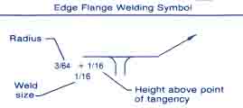
Edge Flange Symbol Shape
The edge flange weld symbol consists of two parallel lines with a curled or flared element, representing the flanged edge profile. It is placed on the reference line of the welding symbol. Because edge flange welds have no arrow side or other side significance, there is no convention about whether the symbol sits above or below the line — dimensions are placed on the same side as the symbol.
When to Specify an Edge Flange Weld
Edge flange welds are appropriate when all of the following conditions are met:
- The base material is light gauge (typically 0.5 mm to 3 mm thickness)
- Both sheets can be flanged along the joining edge before assembly
- No filler metal is required — the flanged edge provides sufficient weld metal
- The joint is in an accessible position for fusion welding or resistance welding
Typical applications include HVAC ductwork seams, electrical enclosure edges, automotive door panel hemming, and domestic appliance housings.
Corner Flange Weld
The corner flange weld symbol applies when two sheets meet at a corner angle (typically 90 degrees) and one or both edges are flanged outward to create the joint. The corner configuration differs fundamentally from the parallel-edge geometry of the edge flange joint.
The Broken Arrow Convention
Where the corner flange joint is not separately detailed in a drawing view that makes the flanged member obvious, AWS A2.4 requires the arrow to have a break in it to indicate which member carries the flange. This broken arrow convention is unique to the corner flange symbol and is not used with edge flange, flash, or upset symbols.
Dimensions of Flange Welds
Reading the dimensional information on a flange weld symbol requires understanding three pieces of data and exactly where each appears on the reference line. This differs from the dimension conventions used for fillet and groove weld symbols.
Multiple-Joint Flange Welds
When a flange weld joins more than two pieces — for example, a sandwich construction where one or more intermediate sheets are inserted between the two outer flanged pieces — the same flange weld symbol is used regardless of how many intermediate pieces are present. The symbol specifies the joint type, not the number of intermediate layers. Any special requirements for multi-piece stacks should be noted in the tail or on the drawing.
Flash and Upset Weld Symbols
Flash welding (FW) and upset welding (UW) are resistance welding processes — they generate heat by passing high electrical current through the joint area. Unlike arc welding, no arc is struck and no shielding gas is required. Both processes produce butt joints without filler metal and are suited to joining parts with comparable cross-sections.
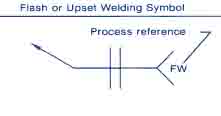
Symbol Placement: Centred on the Reference Line
The defining visual characteristic of the flash and upset weld symbol is that it sits exactly centred on the reference line, not above or below it. This centring is mandatory under the pre-2020 AWS A2.4 convention and immediately signals that neither arrow side nor other side significance applies. The weld is made at the faying surfaces of both parts simultaneously — there is no concept of “near side” or “far side.”
No Dimension Requirement
Unlike groove or fillet welds, flash and upset weld symbols do not require dimensional information on the welding symbol itself. The joint geometry — the cross-section of the parts, the upset distance, and the clamping die positions — is controlled by the welding machine program and the WPS rather than by symbol notation. If process parameters must be specified, they are placed in the tail of the welding symbol or referenced to a separate WPS document.
AWS A2.4:2020 — Important Changes to Flash and Upset Symbols
The 2020 edition of AWS A2.4 introduced a significant change for flash and upset weld symbols: the traditional graphical symbols for flash welding and upset welding are no longer supported. This is one of the most consequential revisions in recent editions of the standard.
| Convention | Pre-2020 AWS A2.4 | AWS A2.4:2020 (Current) |
|---|---|---|
| Flash Weld (FW) | Graphical symbol centred on reference line | Reference line + arrow, “FW” in tail |
| Upset Weld (UW) | Graphical symbol centred on reference line | Reference line + arrow, “UW” in tail |
| Arrow/Other Side | No significance (centred symbol) | No significance |
| Dimensions on symbol | Not required | Not required |
| Supplementary symbols | Surface contour symbols permitted | Contour requirements noted in tail or WPS |
Surface Contour Symbols for Flash and Upset Welds
Surface contour requirements for flash and upset welds are specified in the same way as for fillet welds — using the flat, convex, or concave contour symbols, with an optional finish method designator.

Contour Symbol Summary
| Contour Requirement | Symbol | Finish Designator Options | Typical Application |
|---|---|---|---|
| Flat (flush) | Horizontal line above/below symbol | G, M, C | Railway rail welding, structural butt joints |
| Convex | Arc above symbol | G, M, C | Ring welding, chain links |
| Concave | Arc below symbol | G, M, C | Tube ends, flanged rings |
The finish designators indicate the method by which the surface contour is to be achieved: G for grinding, M for machining, and C for chipping. In most production flash welding applications, the expelled flash is mechanically trimmed by a dedicated flash trimmer built into the welding machine immediately after the upset stroke, rather than by a separate secondary operation.
The Flash Welding Process Explained
Flash welding is a resistance welding process that produces a butt joint through a two-stage sequence: a flashing stage followed by an upset (forging) stage. It is used for joining parts with similar cross-sectional shapes and is capable of welding both similar and certain dissimilar metals.
Stage 1 — Flashing
The two workpieces are clamped in copper alloy dies (which also serve as the current-carrying electrodes) and brought slowly toward each other while voltage is applied. When the surfaces make contact at microscopic high points, the high current density at those contact spots causes the metal to vaporise and be forcibly expelled as incandescent particles — the “flash.” This is the flashing action that gives the process its name. The flashing continues as the parts are advanced, progressively heating the entire end face to forging temperature.
Stage 2 — Upset
Once the end faces have reached the required temperature profile, the power is cut and the moveable clamp applies a rapid, high-force upset stroke, forcing the two faces together. The plasticised metal at the interface is squeezed out as a collar of upset material (flash), leaving a solid-state or partially liquid-state weld zone free of contamination because all oxidised material was expelled during the flashing stage. The resulting weld has no fusion zone with entrapped flux or slag — it is a pressure-welded interface with a fine-grained heat-affected zone.
Applicable Materials
| Material Group | Flash Weldable | Notes |
|---|---|---|
| Carbon and alloy steel | Yes | Excellent. Rail, bars, tubes, rings |
| Stainless steel | Yes | Good. Control of HAZ sensitisation required |
| Aluminium alloys | Yes | Good. Flash trimming essential |
| Titanium alloys | Conditional | Requires inert gas shielding at joint area |
| Nickel alloys | Conditional | High-temperature alloys; machine capacity is key |
| Copper alloys | Conditional | High conductivity increases machine power demand |
| Dissimilar metals | Limited | Possible where upsetting characteristics are similar (e.g. Al to Cu, Ni alloy to steel) |
The Upset Welding Process Explained
Upset welding (UW) is closely related to flash welding but differs in one critical way: it is a single-stage operation. In upset welding, the two workpieces are brought together under continuous mechanical pressure before any current is applied. Current is then passed through the joint while the pressure is maintained. The resistance at the faying surfaces heats the metal to forging temperature, at which point the applied pressure consolidates the joint.
Because the parts remain in contact throughout, there is no flashing action and no expelled metal. The joint is formed purely by resistance heating and pressure — closer in mechanism to solid-state forging welding than to the two-stage flash welding process. Upset welding is commonly used for joining wire, rod, and small cross-section bar stock where the cross-sections are uniform and the machine can ensure even current distribution across the entire faying area from the start of the weld cycle.
| Parameter | Flash Welding (FW) | Upset Welding (UW) |
|---|---|---|
| Stages | Two: flashing + upset stroke | One: pressure + current simultaneously |
| Initial part contact | Not in contact at start | In contact under pressure from start |
| Metal expulsion | Significant flash expelled | Minimal — small upset collar only |
| Part preparation | Clean faces preferred but not critical (flash cleans the surface) | Faces must be clean and flat for uniform contact resistance |
| Typical cross-section | Up to very large sections (rails, aerospace components) | Small to medium sections (wire, rod, tube ends) |
| Material loss per side | Greater — flash distance adds to burn-off | Less — upset shortening only |
| Joint quality | Excellent surface preparation by flashing action | Quality highly dependent on surface cleanliness |
Industrial Applications
Flash and upset welding are production-oriented processes found in high-volume manufacturing environments. The following industries are primary users:
Railway Industry
Flash butt welding of continuous welded rail (CWR) is one of the most widespread applications of the process. Rail sections are joined end-to-end to create long seamless tracks, eliminating the expansion gaps that cause the traditional rhythmic clickety-clack of jointed rail. The resulting continuous rail reduces track maintenance requirements, improves ride quality, and allows higher operating speeds. Specialist flash welding vehicles are used for in-track welding of rail on live lines.
Automotive Industry
Wheel rims for passenger cars and commercial vehicles are formed from flat cold-rolled steel strip that is roll-formed into a cylinder and then flash welded at the butt joint before further pressing into the final rim shape. Flywheel ring gears, crankshaft counterweights, and steering column tubes are other common automotive flash weld components. The process is suited to high production rates because it is fully automated and produces consistent joints without operator-dependent variables.
Aerospace Industry
Flash welding is used for landing gear struts, turbine engine ring components, control assemblies, and hollow propeller blades where high strength, consistent metallurgy, and zero filler metal contamination are essential. The tight process control available on programmable flash welding machines makes it suitable for aerospace-grade alloys where the joint properties must meet strict qualification requirements.
Heavy Fabrication and Electrical Industry
Motor and generator frames, transformer cases, and circular flanges are produced by flash welding plate and bar stock rolled into cylindrical form. Conductor bars and busbars for electrical distribution systems are also joined by upset welding because of the excellent electrical conductivity and mechanical strength achieved at the joint.
How Supplementary Symbols Interact with Flash and Upset Symbols
Although flash and upset weld symbols themselves have no arrow side or other side significance, supplementary symbols used in conjunction with them may have such significance. The most relevant supplementary symbols are the surface contour symbols and the backing/melt-through symbols, should they apply. In practice, the contour of a flash weld surface is usually controlled by the trimmer setting on the welding machine, with any post-trim finish requirement noted in the WPS rather than on the drawing symbol.
Reading a Complete Flange Weld Symbol — Step-by-Step
When you encounter a flange weld symbol on a fabrication drawing, work through the following systematic reading sequence to extract all specified information:
Comparison: Flange Welds vs. Groove Welds for Thin Sheet
Engineers specifying joints for light-gauge sheet metal sometimes face a choice between a flange weld and a square groove or fillet weld. The selection criteria depend on sheet thickness, available processes, required appearance, and production volume.
| Factor | Flange Weld | Square Groove / Fillet on Thin Sheet |
|---|---|---|
| Filler metal required | No (flanged edge provides weld metal) | Usually yes (GMAW, GTAW, or resistance spot) |
| Joint preparation | Flanging operation required (press brake or roll) | Edge preparation minimal or none |
| Distortion | Less — flanged stiffening reduces warping | Higher risk with full-penetration groove welds |
| Sheet thickness range | Best for 0.5 mm to 3 mm | Fillet and groove can cover 0.8 mm upward |
| Production suitability | High volume — fast, repeatable | Variable — operator skill required for thin GTAW |
| Appearance | Flush or slightly convex, no external bead | Visible external bead / cap on groove welds |
For further detail on joint type selection, the welding joint types guide on WeldFabWorld covers butt, tee, corner, lap, and edge joint geometries in full, including their applications and preparation requirements.
Recommended Books on Welding Symbols and Processes
Frequently Asked Questions
What is the difference between an edge flange weld and a corner flange weld?
An edge flange weld joins two light-gauge sheets whose edges are both flanged and lying parallel, creating a weld along the flanged edges where the two flanges are fused together. A corner flange weld joins two sheets meeting at a corner angle where one or both edges are flanged outward. The key distinction on the drawing is that a corner flange joint not shown in full detail requires a broken arrow to identify which member carries the flange — a convention unique to the corner flange symbol. Both symbols have no arrow side or other side significance.
Do flange weld symbols have arrow side or other side significance?
No. Both edge flange and corner flange weld symbols have no arrow side or other side significance. The weld symbol is placed on the reference line without the conventional above/below meaning used for fillet or groove welds. Dimensions, however, are always placed on the same side of the reference line as the weld symbol itself — so dimension placement follows the symbol position even though joint face selection is not implied by it.
How are the dimensions of a flange weld shown on the welding symbol?
Flange weld dimensions are placed to the left of the weld symbol, separated by a plus (+) mark, and read left to right as: radius then height above the point of tangency (e.g., “3 + 5” means radius 3 mm, height 5 mm). The weld size (thickness) is placed outward from the flange dimensions. The root opening is not shown on the welding symbol — if specification of root opening is required, it must be shown on the drawing or noted in the tail of the symbol.
Why must flash and upset weld symbols be centred on the reference line?
Flash and upset welding processes join both workpieces symmetrically through the entire cross-section at the faying surface. Because the weld is not confined to one face or side of the joint — it occurs through the full thickness of both parts at the interface — there is no arrow side or other side distinction. AWS A2.4 therefore requires the weld symbol to be centred on the reference line, signalling that the joint is affected equally on both sides simultaneously. Fabricators who see a weld symbol centred on the reference line should immediately recognise it as a flash or upset weld.
Are flash and upset weld symbols still used in the current AWS A2.4 standard?
No. AWS A2.4:2020 removed the dedicated graphical symbols for flash welding and upset welding from the standard. Under the current edition, if a welding symbol is needed for these processes, the recommendation is to use a plain reference line and arrow with either “FW” (flash welding) or “UW” (upset welding) written in the tail of the welding symbol. Engineers working with legacy drawings produced before 2020 may still encounter the old centred graphical symbols, so familiarity with both the pre-2020 and current conventions is important for anyone who reads fabrication drawings in these industries.
What is the difference between flash welding and upset welding?
Flash welding (FW) is a two-stage process: the parts start apart, voltage is applied, and as the parts are slowly advanced the high current density at contact points causes metal to be expelled as flash; once the end faces reach forging temperature, a rapid upset stroke consolidates the joint. Upset welding (UW) is a single-stage process: parts are first clamped together under continuous pressure, then current is applied with pressure maintained throughout, heating the faying surfaces until they reach forging temperature and the applied pressure alone consolidates the joint. Flash welding produces a visible expelled flash collar; upset welding produces only a small upset collar with no expelled particles.
What surface contour symbols are used with flash and upset welds?
The contour symbols for flash and upset welds follow the same conventions as those used for fillet welds per AWS A2.4. The three conditions are flat (flush), convex, and concave, indicated by the corresponding contour symbol placed with the weld symbol. Finish method designators — G for grinding, M for machining, C for chipping — may be added to specify how the specified contour is to be achieved. In most production flash welding, the expelled flash is trimmed by an automatic flash trimmer built into the welding machine immediately after the upset stroke.
What industries commonly use flange welds on fabrication drawings?
Flange welds appear most frequently in HVAC ductwork fabrication, automotive body panel assembly, light-gauge sheet metal enclosures, electrical cabinets, and domestic appliance manufacturing. The edge and corner flange joint configurations are ideal wherever thin sheet metal (typically below 3 mm) must be joined cleanly without filler metal, since the flanged material itself provides the weld metal through melting of the turned-up edges. For guidance on specifying other types of joints for sheet metal fabrication, see the welding joints guide on WeldFabWorld.