Root Cause Analysis for Weld Failures — A QA/QC Approach
Weld failure root cause analysis is the disciplined process of tracing a cracked, leaking, or rejected weld back to the specific, controllable condition that actually caused it, instead of stopping at the visible symptom. For a welding engineer, QA/QC inspector, or fabrication supervisor working to ASME BPVC requirements, that distinction is not academic: repairing a crack without understanding why it formed all but guarantees the same failure will resurface, often in a more expensive location, a later project stage, or a more demanding service environment.
This guide walks through a complete QA/QC approach to weld failure investigation: the six categories of root cause every investigator should check, how the most common failure modes, cracking, porosity, lack of fusion, brittle fracture, fatigue, and corrosion-driven cracking, map back to those categories, and a step-by-step process from containment through verified closure. You will also find a comparison of the four investigation tools engineers actually reach for, plus a fully worked case study that traces a cracked girth weld back to its root cause.
Root cause analysis is deliberately reactive, starting only after a failure has already occurred. It is the natural counterpart to FMEA (Failure Mode and Effects Analysis), the proactive tool used to catch these same failure modes before they ever reach a real weld; the difference between the two, and how they work together, is covered in the section immediately below.
This guide covers reactive investigation: tracing a weld failure that has already occurred back to its controllable cause. Pair it with a proactive risk tool if you want to catch the same failure modes before they happen — the relationship between the two approaches is explained in the next section.
What Is Root Cause Analysis in Welding QA/QC?
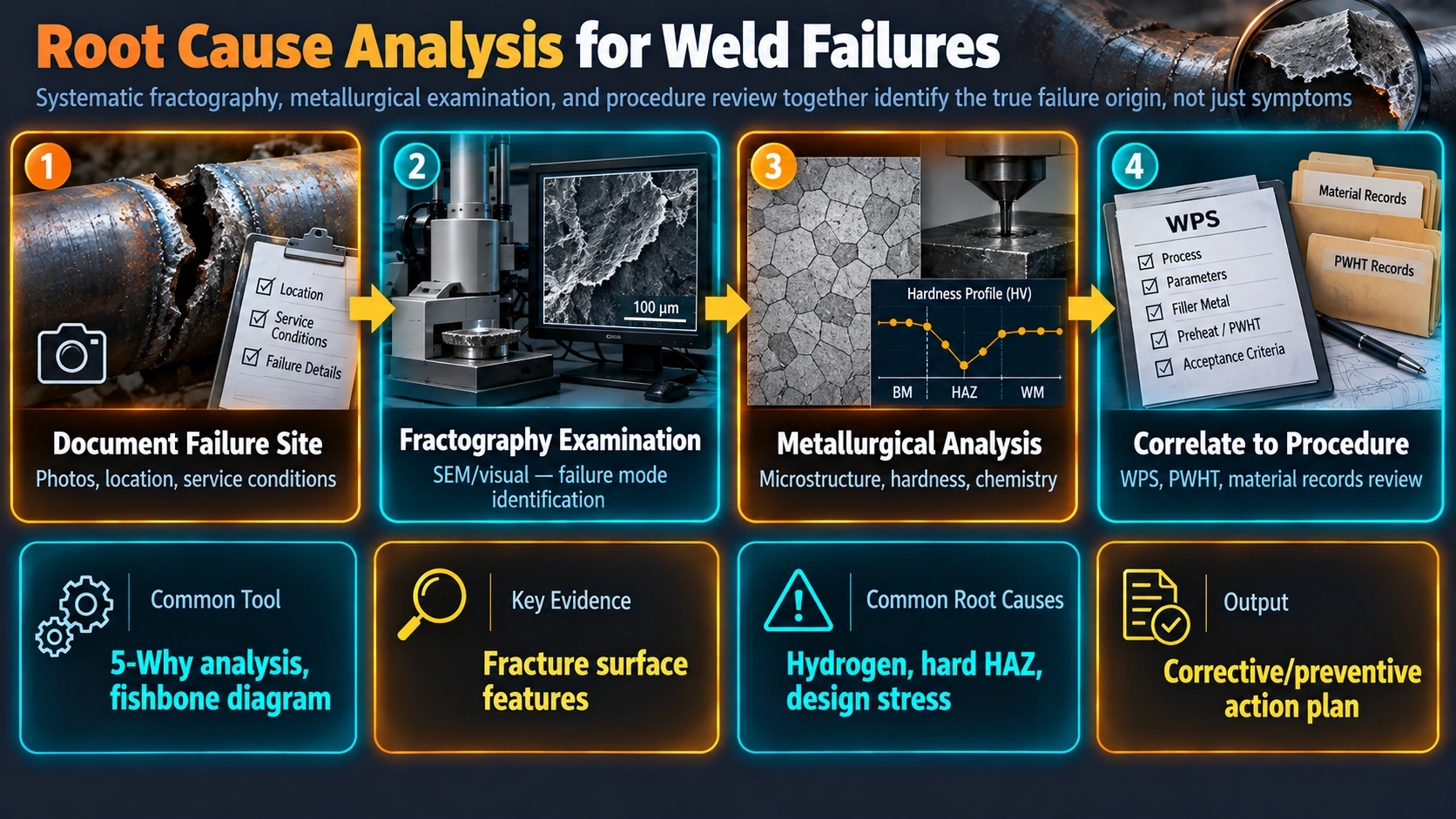
Root cause analysis (RCA) is the umbrella term for any structured method that starts with a symptom, a crack, a failed hydrotest, a rejected radiograph, and works backward through the evidence until it reaches a condition that is both controllable and sufficient to explain the failure on its own. The output of a good RCA is a single sentence an auditor could not easily argue with: “This weld cracked because X, and if X is corrected, this failure mode will not recur.” Anything short of that, a plausible story that still leaves room for doubt, is a hypothesis, not a finding.
In a fabrication or pressure-equipment QA/QC system, RCA sits downstream of two other functions: inspection, which finds the defect, and disposition, which decides whether to repair, reject, or accept it under an engineering evaluation. RCA answers the question those two steps deliberately leave open: not just what the defect is, but why the process allowed it to happen, so the fix addresses the system rather than the single weld.
RCA vs. FMEA: Reactive vs. Proactive Quality Tools
RCA and Failure Mode and Effects Analysis (FMEA) are frequently confused because they use the same vocabulary, failure mode, cause, effect, but they run in opposite directions. FMEA is proactive: before a single weld is made, a cross-functional team scores every plausible failure mode for severity, occurrence, and detection, then works down the highest-risk items and designs them out. RCA is reactive: it only starts once a real defect has already been found, and it works backward from physical evidence rather than forward from a risk score.
The two are meant to close a loop, not compete. A verified RCA finding is exactly the kind of real-world data an FMEA team needs to correct an occurrence rating that was set too low, and a failure mode that was already flagged high-risk in the FMEA gives an RCA investigator a documented head start on where to look first.
Why Weld Failures Happen: The Six Root-Cause Categories
Every credible weld failure investigation checks the same six categories, commonly abbreviated 6M, before settling on a cause. The value of the framework is less in the labels themselves and more in what it stops an investigator from skipping: it is easy to jump straight to “the welder made a mistake” (Man) and never check whether the gauge used to verify preheat was in calibration (Measurement). Table 1 maps each category to the root causes that show up most often on welding defects in pressure equipment and piping fabrication.
| Category | Typical Root Causes in Welding | Example Resulting Defect |
|---|---|---|
| Material | Wrong or substituted base metal/consumable, elevated carbon equivalent, non-conforming heat, contaminated joint surface | Hydrogen cracking, porosity |
| Method | Incorrect WPS parameters, wrong process selection, inadequate preheat or PWHT, poor joint design | Lack of fusion, HAZ cracking |
| Machine | Worn contact tip, faulty gas regulator, mis-calibrated power source | Arc instability defects, porosity |
| Man | Welder skill or qualification gap, fatigue, rushed schedule, misread welding symbols | Incomplete fusion, wrong joint executed |
| Measurement | Uncalibrated NDT equipment, wrong acceptance criteria applied, missed inspection hold point | Undetected defect escapes to service |
| Environment | Wind or draft disturbing shielding gas, high humidity, extreme ambient temperature affecting preheat retention | Porosity, cold cracking |
Common Weld Failure Modes and Their Root Causes
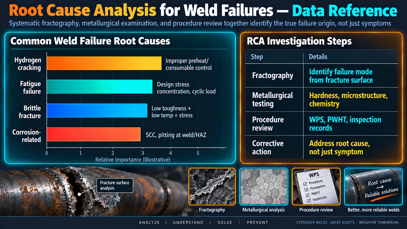
Once a failure has been classified, the 6M framework narrows quickly, because most weld failure modes are strongly associated with a short list of likely causes. Table 2 is the reference an investigator should start from before opening a full 5-Why or Fishbone session; it also lists the detection method most likely to confirm each mode.
| Failure Mode | Likely Root Cause(s) | Detection Method | Severity |
|---|---|---|---|
| Hydrogen-induced (cold) cracking | Damp/under-baked low-hydrogen electrode, moisture in shielding gas, insufficient preheat, high carbon equivalent | Delayed UT/RT, hardness survey, macro-etch | Critical |
| Solidification (hot) cracking | High sulfur/phosphorus content, excess restraint, unfavorable bead shape, low delta ferrite | PT/MT on crater and centerline, RT | Critical |
| Lamellar tearing | Low through-thickness ductility base plate, heavy T/K-joint restraint | UT before and after welding, MT | Critical |
| Porosity | Contaminated shielding gas, moisture/rust/oil on the joint, excessive arc length | RT, visual on surface-breaking pores | Major |
| Lack of fusion / incomplete penetration | Wrong travel speed or angle, low heat input, poor fit-up | UT/RT | Critical |
| Brittle fracture | Inadequate toughness for service temperature, missed impact test requirement | Charpy V-notch qualification, fractography | Critical |
| Fatigue cracking | Cyclic loading concentrated at weld toe, poor profile, missed toe-grinding | PT/MT at critical locations, replication | Major |
| Sulfide stress cracking | Hard HAZ combined with tensile residual stress in H2S service | Hardness survey, PT | Critical |
Cracking Mechanisms
Cracks account for the majority of weld rejections that escalate into a full RCA, because unlike porosity or undercut, a crack is a planar, stress-concentrating defect that can propagate under load long after the weld has passed its original inspection.
Hydrogen-Induced (Cold) Cracking
This is the failure mode most QA/QC programs invest the most preventive effort in, because it is delayed: cracks can appear hours or even days after welding, which is exactly why codes require a waiting period before final NDT on higher-strength or thicker sections. The root cause is almost always diffusible hydrogen entering the weld pool from a damp electrode coating, wet flux, or moisture on the joint, combined with a susceptible microstructure and residual stress. Checking the base metal’s carbon equivalent against the preheat table in the WPS, and verifying electrode baking and holding-oven records against the SMAW consumable control procedure, is the first move in almost every cold-cracking RCA.
Solidification (Hot) Cracking
Hot cracking forms while the weld metal is still solidifying, driven by low-melting-point sulfur and phosphorus segregating to grain boundaries under restraint. In austenitic stainless steel welds, insufficient delta ferrite content is the single most common controllable root cause, since ferrite disrupts the continuous liquid film that allows the crack to propagate along solidifying grain boundaries.
Lamellar Tearing
Unlike most weld defects, lamellar tearing occurs in the base metal itself, away from the fusion zone, driven by through-thickness tensile stress from weld shrinkage acting on a plate with poor through-thickness ductility. It is a favorite RCA case study precisely because it can pass RT and even an initial hydrotest before ultrasonic examination or in-service loading reveals it.
Porosity and Lack of Fusion
Porosity is rarely a single-cause failure; it is almost always a Material-Environment combination, contaminated or insufficient shielding gas meeting a joint that was not adequately cleaned or shielded from draft. Lack of fusion and incomplete penetration, by contrast, are usually Method or Man category failures: heat input, travel angle, and joint fit-up that fell outside the qualified WPS window, which is why a lack-of-fusion RCA should always start with a side-by-side comparison of the actual welding parameters against the qualified WPS and PQR record, not just the welder’s account of what happened.
Brittle Fracture and Fatigue
Brittle fracture investigations center on toughness: was the material’s Charpy V-notch impact energy at the minimum design metal temperature actually verified, or was an exemption assumed that did not apply? The UG-84 impact testing requirements in ASME Section VIII Division 1 are the reference point for almost every brittle fracture RCA on pressure vessel welds. Fatigue failures, by contrast, are a geometry and cycle-counting problem: the root cause is usually a stress concentration at the weld toe, from undercut, poor profile, or a design detail that was never intended for cyclic service, rather than a material or process defect.
Corrosion-Related Service Failures
Failures that surface months or years into service usually trace back to a metallurgical condition set during welding rather than a workmanship defect. Sulfide stress cracking in sour service is a classic example: a HAZ hardness that exceeded the NACE MR0175 limit at the time of welding sat dormant until residual stress and H2S exposure combined to crack it. Pitting and crevice corrosion in stainless and duplex welds are frequently verified with an ASTM G48 test on a sister sample once a failure is suspected, and creep-related Type IV cracking in the intercritical HAZ of P91 material is almost always traced back to a PWHT time-temperature deviation during the original fabrication.
Do not let schedule pressure turn your first plausible theory into the official root cause. A corrective action built on an unverified guess will not stop the failure, and it will make the next investigation harder, because the real evidence trail has already gone cold by the time the mistake becomes obvious.
The Root Cause Analysis Process: Step by Step
A defensible RCA follows the same six phases regardless of which analytical tool it uses to get from evidence to cause. Skipping straight to “Analyze” without properly containing the situation or collecting evidence first is the single most common reason an RCA gets challenged later, whether by an internal audit, a customer, or a code inspector.
Step 1: Containment and Immediate Actions
Before any analysis begins, isolate the immediate risk. That means quarantining the failed weld itself, but just as importantly, identifying and holding every “sister” weld made by the same welder, the same WPS, or the same consumable batch until the investigation clears them. Containment is a scope decision, not a root cause, and treating it as one is a common shortcut that leaves related defects undiscovered in the field.
Step 2: Evidence Collection and Documentation
Gather the physical evidence, macro and micro sections, hardness surveys, fracture surfaces, and the full paper trail: WPS/PQR revision in force, welder qualification and continuity records, consumable heat certificates, preheat and interpass logs, and every prior NDT report on that weld. Evidence collected after the fact is far weaker than evidence collected before repair begins.
Photograph the failure before any cleaning, grinding, or repair begins. Fracture surface morphology, often the single best clue for distinguishing hydrogen cracking from fatigue or brittle fracture, is destroyed the moment someone reaches for a grinder.
Step 3: Root Cause Analysis Techniques
With evidence in hand, apply 5-Why, a Fishbone diagram, or Fault Tree Analysis (covered in detail in the next section) to work from the confirmed failure mode back through the causal chain to a controllable condition.
Step 4: Root Cause Verification
A root cause is not confirmed until it is tested against the physical evidence, not just judged plausible by the team. If the proposed cause is “damp electrode,” does the diffusible hydrogen data, the storage log, and the crack morphology all agree? If any piece of evidence contradicts the theory, the investigation is not finished.
Step 5: Corrective and Preventive Action (CAPA)
The corrective action must target the verified cause specifically, not a general “retrain everyone” response. A procedural gap needs a procedural fix: a revised WPS, an added QC hold point, a changed consumable control step, tied to the exact condition identified in Step 4.
Step 6: Effectiveness Verification and Closure
Monitor a defined number of subsequent welds under tightened inspection before relaxing back to normal sampling. Only then does the RCA or 8D report close, with the finding fed back into the WPS, training program, or FMEA as appropriate.
Choosing the Right RCA Tool: 5-Why vs. Fishbone vs. FTA vs. 8D
None of these four tools is universally “better”; each fits a different failure profile and a different reporting requirement. Table 3 is a quick reference for picking the right one before the investigation meeting starts.
| Tool | Best Used When | Strengths | Limitations |
|---|---|---|---|
| 5-Why | One dominant, fairly linear cause; fast turnaround needed | Simple, no special training, quick to document | Can miss simultaneous causes; risk of stopping too early |
| Fishbone / Ishikawa | Unclear which category the cause sits in; team brainstorm needed | Visual, comprehensive across all 6M categories | Does not rank causes or show causal chains |
| Fault Tree Analysis | Multiple interacting causes on safety-critical or code-stamped equipment | Rigorous logic gates (AND/OR) between combined causes | Time-intensive; needs a trained facilitator |
| 8D | Formal customer-facing corrective action required | Complete documentation trail with containment and verification | Heavier process; can feel excessive for minor issues |
Worked Case Study: Root Cause Analysis of a Cracked Girth Weld
The following walkthrough illustrates the process end to end using a realistic, representative scenario built for teaching purposes.
Background and Containment
A carbon steel girth weld in a process piping line, welded SMAW with a low-hydrogen E7018 electrode, showed a transverse indication near the weld toe during pre-hydrotest radiography. The line was quarantined, and every girth weld made by the same welder during the same shift, using the same electrode issue, was pulled from the schedule pending investigation.
The 5-Why Chain
A macro-etch cross-section and hardness survey confirmed the crack sat in the HAZ with locally elevated hardness, consistent with hydrogen-induced cold cracking rather than a mechanical or fatigue mechanism. From there, the investigation asked why five times in sequence, moving from the confirmed cracking mechanism, to elevated diffusible hydrogen in the deposit, to moisture absorbed by the electrode coating, to an exposure time that exceeded the WPS out-of-oven limit, and finally to the controllable condition: field welders had no rod quiver or heated holding oven available at the work location, because the consumable control procedure only mandated one for shop welders.
Corrective Action Taken
The consumable control procedure was revised to require heated rod quivers or portable holding ovens at every field welding location, not only in the shop. Welders and QC inspectors were retrained on out-of-oven exposure limits, a QC hold point was added to verify quiver use before the root pass, and every sister weld from the affected shift was re-examined by UT before the hold was released.
Frame the investigation around the process gap, not the individual. A welder who used an over-exposed electrode because no quiver was issued is evidence of a system failure, not a disciplinary case, and treating it as one only makes the next investigation harder to run honestly.
Quantifying Weld Quality: DPPM and Rejection Rate Tracking
A single RCA fixes one failure mode. Tracking defect rates over time tells you whether your quality system is actually improving, or whether the same root causes keep resurfacing under a different work order number.
Neither number replaces the RCA itself. What they add is a trigger: a DPPM or rejection rate that climbs for a specific welder, WPS, or shift is the signal that tells a QA manager where to point the next investigation before a customer or an inspector does it for them.
Documentation and QA/QC Records for Failure Investigations
An RCA finding is only as strong as the paper trail behind it. At minimum, a defensible investigation file includes the WPS and PQR revision in force at the time of welding, welder qualification and continuity records, consumable heat and batch certificates with the storage and issue log, preheat and interpass temperature charts, the PWHT chart where applicable, every relevant NDT report, and photographs of the failure taken before any repair. This is also the point in the investigation where root cause and contributing factor need to be kept clearly separate.
A contributing factor made the failure more likely; a root cause is the condition that, if corrected, would have prevented the failure outright. A rushed schedule is usually a contributing factor. The consumable control procedure that let a welder use an over-exposed electrode under that schedule pressure is usually the root cause.
Applicable Codes and Standards for Weld Failure Investigation
Most weld failure investigations on ASME BPVC equipment touch at least three code references before the corrective action is finalized.
| Standard | Relevance to Weld Failure Investigation |
|---|---|
| ASME BPVC Section V | Governs the NDE methods used to detect and size the defect |
| ASME BPVC Section IX | Governs the WPS/PQR and welder qualification records reviewed during the investigation |
| API 579-1 / ASME FFS-1 | Fitness-For-Service assessment when the component must stay in service pending repair |
| ASME PCC-2 | Repair methods once the root cause and repair scope have been defined |
| NACE MR0175 / ISO 15156 | Hardness and material limits relevant to sour-service failure investigations |
If the failed component must remain in service while the corrective action is developed, an API 579-1/ASME FFS-1 fitness-for-service assessment, not just the RCA report, is what actually authorizes continued operation.
Recommended References for Failure Investigation
Disclosure: WeldFabWorld participates in the Amazon Associates programme (StoreID: neha0fe8-21). If you purchase through these links, we may earn a small commission at no extra cost to you. This helps support free technical content on this site.
Frequently Asked Questions
What is root cause analysis (RCA) in welding QA/QC?
RCA is the structured investigation that traces a weld failure or nonconformance back to the specific controllable condition that caused it, rather than stopping at the visible defect. In welding QA/QC that means combining physical evidence, such as macro sections, hardness surveys, and fractography, with procedural records such as the WPS, PQR, welder qualifications, and consumable control logs, to build a defensible causal chain. The output is not just what broke but why the process allowed it to break, which is what makes the resulting corrective action durable rather than cosmetic. It is the natural complement to Failure Mode and Effects Analysis (FMEA), which tries to catch the same failure modes before they ever reach a real weld.
How is RCA different from FMEA?
FMEA is proactive: a cross-functional team rates potential failure modes for severity, occurrence, and detection before production starts, then works down the highest-risk items. RCA is reactive: it starts after a real failure, crack, or rejected weld has already been found, and works backward from physical evidence to the controllable cause. The two feed each other in practice; every RCA finding is a candidate line item for the next FMEA revision, and every high-risk FMEA item that does eventually fail becomes an RCA case with a documented head start.
What is the 6M framework used in weld failure root cause analysis?
The 6M framework groups every possible root cause into six buckets: Material, Method, Machine, Man, Measurement, and Environment. It is the same structure used to build a fishbone or Ishikawa diagram, and it forces the investigation team to check categories they might otherwise skip, such as measurement error, instead of jumping straight to welder error. Most real weld failures trace back to more than one of these categories acting together.
Which RCA tool should I use: 5-Why, Fishbone, Fault Tree Analysis, or 8D?
Use 5-Why when the failure has one dominant, fairly linear cause and you need a fast answer. Use a Fishbone or Ishikawa diagram when you are not sure which category the cause sits in and need a team to brainstorm broadly. Reach for Fault Tree Analysis when several causes could combine to produce the failure, particularly on safety-critical or code-stamped equipment. Use the full 8D methodology when a customer, certifying body, or your own quality system requires a documented, team-based investigation with containment, root cause, corrective action, and verified closure.
What NDT methods are used to investigate a weld failure?
Visual examination comes first and is often enough to classify the general defect family. Surface methods, penetrant testing and magnetic particle testing, confirm and size surface-breaking cracks, undercut, and porosity, while volumetric methods, radiography and ultrasonic testing, find subsurface lack of fusion, porosity, and cracking. Where the failure has already occurred, a hardness survey and a metallographic cross-section usually confirm or rule out hydrogen cracking. See the non-destructive testing guide and mechanical testing overview for the full method-by-method breakdown.
What is 8D and how does it apply to a weld failure investigation?
8D, or Eight Disciplines, is a structured problem-solving report format that many EPCs and OEMs require for any weld failure that escapes to a customer or a hydrotest. The early disciplines cover forming the team, describing the problem precisely, and containing it by quarantining sister welds made by the same welder, WPS, or consumable batch. Later disciplines identify the verified root cause, implement the permanent corrective action, address systemic prevention, and close the report with the team’s findings documented. It is heavier than a simple 5-Why, but it is the format most likely to satisfy a customer audit.
How do you prevent the same weld failure from happening again?
Preventing recurrence starts with verifying the root cause against physical evidence rather than accepting the first plausible theory, since a corrective action built on the wrong cause will not stop the failure. Once confirmed, the corrective action has to target that specific condition, for example revising a WPS preheat requirement or changing consumable storage controls. The action then needs a defined verification period, monitored with tighter inspection, before returning to normal sampling and feeding the finding back into the WPS, training program, or FMEA.
What documentation should be captured during a weld failure investigation?
Pull the WPS and PQR revision in force at the time of welding, the welder’s qualification record, and the consumable heat certificates with the storage and issue log. Capture the preheat and interpass temperature log, the PWHT chart if applicable, and every NDT report for that weld. Photograph the failure before cleaning or repair, and retain the macro/micro sections and hardness survey data. All of this feeds the final report, cross-referenced against the relevant ASME Section IX qualification records so the finding is traceable during a future code audit.