ASME Section VIII Div 2 vs Div 1: Design-by-Rule vs Design-by-Analysis
ASME Section VIII Div 2 vs Div 1 is the first design-basis decision on most pressure vessel projects, and it comes down to design by rule against design by analysis. Division 1 gives prescriptive formulas and a conservative design margin. Division 2 allows lower margins and thinner walls in return for stricter materials, documentation and analysis.
Quick Answer
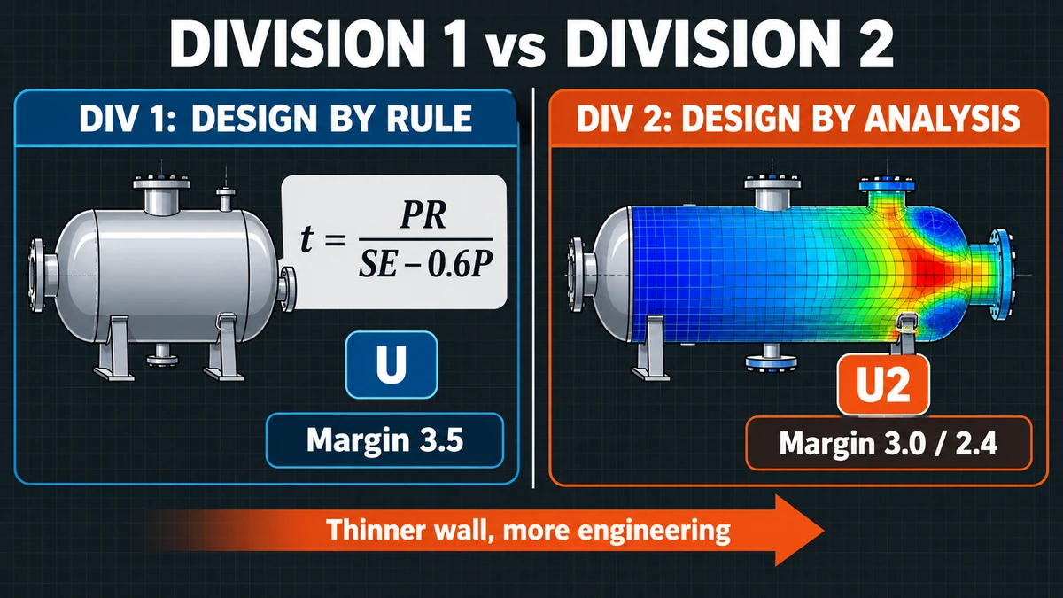
ASME Section VIII Div 1 is a design-by-rule code with a 3.5 design margin on tensile strength and a U stamp. Div 2 uses design by rule in Part 4 plus design by analysis in Part 5, with a 3.0 or 2.4 margin, a certified User’s Design Specification and a U2 stamp. Div 2 gives thinner walls but demands more engineering, documentation and examination.
For the full Division 1 scope, see our ASME Section VIII Division 1 overview. For the wider picture of vessel types and the codes behind them, read the pressure vessel types and design codes guide.
This guide explains how each Division sizes a vessel, how the design margins differ, what Part 5 analysis actually checks, and how documents, testing and fatigue rules change. It includes a worked shell thickness comparison, a decision flowchart and a paragraph finder, so you can justify the choice on your next project.
Key Takeaways
- Division 1 is design by rule: formulas, a 3.5 design margin on tensile strength, and a U stamp.
- Division 2 has two design routes: Part 4 design by rule and Part 5 design by analysis. Both use lower margins than Division 1.
- In the 2017 to 2023 editions, Division 2 margins are 3.0 for Class 1 and 2.4 for Class 2. Confirm the class structure in the 2025 edition.
- Division 2 requires a certified User’s Design Specification and Manufacturer’s Design Report, and a vessel receives the U2 stamp.
- In the worked example below, a Division 2 shell is roughly 15 to 21 percent thinner than the Division 1 shell for the same duty.
- Requirements depend on the code edition and contract specification applicable to your project.
What Is the Difference Between Division 1 and Division 2?
ASME Section VIII Division 1 is a design-by-rule code that sizes parts with prescribed formulas and a design margin of 3.5 on tensile strength. Division 2 allows a lower margin of 3.0 or 2.4, and adds design by analysis, a certified User’s Design Specification, stricter examination and the U2 stamp.
Both Divisions cover pressure vessels above 15 psi (103 kPa), and both are complete rule sets for design, materials, fabrication, examination, testing and overpressure protection. A vessel is built to one Division only. The table gives the headline differences.
| Aspect | Division 1 | Division 2 |
|---|---|---|
| Design approach | Design by rule (UG and related paragraphs) | Design by rule (Part 4) and design by analysis (Part 5) |
| Design margin on tensile strength | 3.5 | 3.0 (Class 1) or 2.4 (Class 2) in the 2017 to 2023 editions |
| Allowable stress source | Section II Part D, Table 1A | Section II Part D, Table 5A |
| User’s Design Specification | User establishes requirements; no certified format | Mandatory, with defined certification |
| Certification mark | U | U2 |
| Fatigue | No analysis method; cyclic loads must be considered | Screening and fatigue assessment in Part 5 |
| Typical pressure range | Rules formulated for pressures up to 3,000 psi (20 MPa) | Common for higher pressures; Division 3 normally above 10,000 psi |
What Is Design by Rule?
Design by rule sizes a vessel part with formulas and detailing requirements printed in the code, so the designer does not need to compute local stresses. The rules reflect decades of experience and testing on common shapes under pressure.
In Division 1, shell thickness comes from paragraph UG-27. For a cylindrical shell under internal pressure, the circumferential stress formula is t = PR / (SE – 0.6P), where P is design pressure, R is inside radius, S is allowable stress and E is joint efficiency. The UG-27 shell thickness calculator applies it directly.
Division 2 also contains design by rule, in Part 4, with its own formulas for shells, heads, nozzles and flanges. That is why Division 2 is not “analysis only”. Many Division 2 vessels use Part 4 for most parts and apply analysis only to details the rules do not cover.
Loads other than pressure are handled with limited guidance. Division 1 paragraph UG-22 lists loadings such as weight, wind, seismic and thermal effects that the designer must consider, but it gives no stress-based method for combining them. Where its rules are silent, paragraph U-2(g) lets the manufacturer provide a design method acceptable to the Inspector.
What Is Design by Analysis?
Design by analysis is a design method that proves a vessel component safe by evaluating computed stresses and strains against defined failure modes, instead of sizing the part with prescribed formulas.
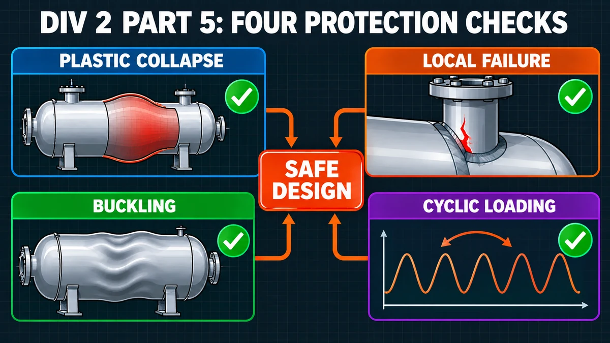
Division 2 Part 5 defines design by analysis. It does not ask whether a stress is below an allowable at a point. It asks whether the component is protected against four failure modes, each with its own acceptance criteria.
| Protection against | Failure it prevents | Part 5 paragraph |
|---|---|---|
| Plastic collapse | Gross yielding and loss of load-carrying capacity | 5.2 |
| Local failure | Rupture at a local region of high strain or stress concentration | 5.3 |
| Buckling | Instability from compressive or external pressure loads | 5.4 |
| Cyclic loading | Fatigue and ratcheting from repeated load changes | 5.5 |
Which Analysis Methods Does Part 5 Allow?
For plastic collapse, Part 5 offers three alternative methods, each progressively less conservative and more demanding to perform:
- Elastic stress analysis (5.2.2): stresses are classified and compared with category limits.
- Limit load analysis (5.2.3): a perfectly plastic model finds the load at which collapse occurs.
- Elastic-plastic stress analysis (5.2.4): a realistic material model is loaded in factored steps to show the component stays stable.
Protection against local failure can be shown by an elastic analysis with a triaxial stress limit, or by an elastic-plastic analysis that compares equivalent plastic strain with a limiting strain. The elastic-plastic route is the more accurate of the two.
How Are Stresses Classified in Elastic Analysis?
Elastic analysis splits computed stresses into categories: primary membrane (Pm), local primary membrane (PL), primary bending (Pb), secondary (Q) and peak (F). Each category has its own limit because each contributes differently to collapse, ratcheting or fatigue. The classification step, often done by linearizing finite element results across the wall, is where analysts need the most judgement.
How Do Design Margins and Allowable Stresses Differ?
A design margin is the factor by which the code divides a material strength to set the allowable stress. Division 1 divides tensile strength by 3.5, while Division 2 divides it by 3.0 (Class 1) or 2.4 (Class 2) in the 2017 to 2023 editions. The yield criterion, one and a half on yield, is the same in both.
The 3.5 margin in Division 1 replaced 4.0 in the 1999 addenda. The 2.4 margin in Division 2 dates from its 2007 rewrite, which paired the lower margin with stricter material, design and examination rules. Allowable stresses come from Section II Part D, Table 1A for Division 1 and Table 5A for Division 2.
| Basis | Governing criterion | Allowable stress S |
|---|---|---|
| Division 1 | Tensile strength 70 ksi / 3.5 | 20.0 ksi (138 MPa) |
| Division 2, Class 1 | Tensile strength 70 ksi / 3.0 | 23.3 ksi (161 MPa) |
| Division 2, Class 2 | Yield strength 38 ksi / 1.5 (governs over 70 / 2.4 = 29.2 ksi) | 25.3 ksi (174 MPa) |
For Class 2 carbon steel, the yield criterion governs, so a lower margin on tensile strength does not raise the allowable further. Take the values for your actual material and temperature from the tables of the edition in your contract.
Worked Example: How Much Thinner Is a Division 2 Shell?
The required thickness of a cylindrical shell under internal pressure shows the effect of the allowable stress directly. The inputs are assumed for illustration: SA-516 Grade 70, design pressure 5 MPa, inside diameter 2,000 mm (R = 1,000 mm), joint efficiency E = 1.0 in both Divisions, and no corrosion allowance.
The shell weight falls by roughly the same percentage. That saving is real on thick, high-pressure shells, but it is not the whole picture. Heads, nozzles, flanges and supports must also be checked, corrosion allowance is added to each thickness, and Division 2 adds engineering, certification and examination cost. Division 2 results always depend on the code edition and the allowable stress tables in force.
How Do Documents and Responsibilities Differ?
Division 2 formalizes who owns the design basis and who certifies the calculations, while Division 1 leaves much of this to normal contract practice. This is one of the practical reasons owners choose Division 1 for routine vessels.
| Item | Division 1 | Division 2 |
|---|---|---|
| Design basis from the user | User or agent establishes design requirements under U-2(a) | User’s Design Specification (UDS) is mandatory and certified |
| Manufacturer’s design record | Design calculations to the code | Manufacturer’s Design Report (MDR) is mandatory and certified |
| Engineer certification | Not normally required | Registered Professional Engineer, with requirements that differ by class |
| Manufacturer’s data report | Form U-1 | Form A-1 |
| Certification mark | U | U2 |
In Division 2, the UDS and MDR carry the certification load. For Class 1 vessels, the UDS needs certification by a Registered Professional Engineer only when a fatigue analysis is necessary. Class 2 carries broader certification duties. Read Part 2 of Division 2 for the exact wording. The different marks and what they authorize are covered in the guide to ASME U and U2 certification stamps.
How Do Materials, Fabrication and Testing Differ?
Division 2 generally pairs its lower margin with tighter requirements on materials, welded joint details, examination and pressure testing. The exact rules sit in Parts 3, 6, 7 and 8 of Division 2 and differ by class.
- Hydrostatic test: Division 1 requires 1.3 times the MAWP, multiplied by the ratio of allowable stress at test temperature to allowable stress at design temperature (UG-99). Division 2 uses its own factors, which depend on class and edition, and requires the hydrotest stress to be calculated during design.
- Nozzle welds: Division 1 permits partial penetration nozzle welds in many cases. Division 2 requires full penetration nozzle welds.
- Examination: Division 2 generally requires more extensive volumetric examination. See the ASME Section V nondestructive examination overview for the methods and their acceptance basis.
- Impact testing: both Divisions require toughness evaluation for low-temperature service, with different rules. Division 1 requirements are detailed in the UG-84 Charpy impact requirements article.
- Heat treatment of test coupons: both require simulation of production heat treatment. The paragraphs and differences are covered in simulation heat treatment requirements.
- Special joints: tube-to-tubesheet welds in Division 2 call for mandatory mockup qualification, as covered in tube-to-tubesheet welder qualification.
Welding procedure and welder qualification follow Section IX in both Divisions. The structure of that standard is explained in the Section IX overview.
How Do the Divisions Treat Fatigue and Cyclic Service?
Division 2 requires designers to evaluate protection against cyclic loading, while Division 1 does not provide a fatigue analysis method. Under Division 1, UG-22 only requires that cyclic and dynamic reactions be considered, so the designer must adopt a method acceptable to the owner and Inspector.
Division 2 Part 5 starts with screening criteria that can show a detailed fatigue analysis is not required. If the screening fails, a fatigue assessment follows, using smooth-bar fatigue curves and stress factors that penalize welded joints. Ratcheting, the progressive deformation that occurs under cyclic load, is checked separately.
Welds are the usual fatigue weak points, so detail matters as much as the analysis method. See why fatigue-critical components should have fewer welds and how residual stress affects fatigue life for the underlying behaviour. Vessels in frequent pressure or temperature cycling, such as reactors with start-up and shutdown cycles, are common reasons to choose Division 2.
When Should You Choose Division 1 or Division 2?
Choose Division 1 for routine vessels where the added cost of Division 2 would exceed the material saving, and choose Division 2 where pressure, thickness, size or cyclic duty make the saving or the analysis valuable. The owner’s specification can also decide the question.
| Choose Division 1 when | Choose Division 2 when |
|---|---|
| The vessel is a standard design with moderate pressure and wall thickness | Walls are thick and the thickness saving is large |
| Speed and low engineering cost matter most | The design pressure is high or the vessel is large |
| Fabricators and inspectors in the supply chain are used to Division 1 | Cyclic service or complex loading calls for analysis |
| The owner has no capacity to issue and certify a UDS | The owner specifies Division 2 or already operates Division 2 equipment |
Can Division 1 and Division 2 Rules Be Mixed?
No. Each Division is a complete, self-contained rule set, and a vessel is designed, fabricated, examined and certified to one Division and receives that Division’s mark. A Division 1 vessel cannot be stamped U2, and Division 2 allowables cannot be used on a U-stamped vessel.
The one controlled bridge is paragraph U-2(g) in Division 1, which allows a manufacturer to use an analysis method for a detail the rules do not cover, with the Inspector’s acceptance. Division 3 sits above both for very high pressure, normally above 10,000 psi, and uses fracture mechanics and fatigue methods.
After construction, both Divisions are covered by in-service rules. The API 510 in-service inspection code applies to vessels built to Division 1 or Division 2, so owners should record the original Division in the equipment file.
Quick Reference: Where to Find It in Each Division
This paragraph finder shows where each subject normally sits. Check each reference against the edition named in your contract, because numbering can change.
| Subject | Division 1 | Division 2 |
|---|---|---|
| Scope and responsibilities | U-1 and U-2 | Parts 1 and 2 |
| Materials and allowable stress | Subsection C and Section II Part D, Table 1A | Part 3 and Section II Part D, Table 5A |
| Design by rule | UG paragraphs, for example UG-27 for shells | Part 4 |
| Design by analysis | Not defined, U-2(g) for details | Part 5 |
| Fabrication | Part UW and related parts | Part 6 |
| Examination and inspection | UW and UG-93 | Part 7 |
| Pressure testing | UG-99 (hydrostatic), UG-100 (pneumatic) | Part 8 |
| Overpressure protection | UG-125 to UG-138 | Part 9 |
| Impact testing | UG-84, with UCS-66 exemptions | Part 3 |
What Are Common Mistakes When Choosing a Division?
The most common mistakes come from treating Division 2 as a free thickness discount or from mixing rules between the Divisions. Reviewers usually catch them at the specification stage, or after fabrication has started.
Watch for these
- Choosing Division 2 for thickness savings without costing the extra engineering, certification and examination.
- Using Division 2 allowable stresses on a Division 1 vessel, or the reverse.
- Assuming Division 2 means analysis only. Part 4 rules are available and are often enough.
- Skipping the hydrotest stress check that Division 2 requires at the design stage.
- Overlooking fatigue screening on vessels with frequent pressure or temperature cycles.
- Failing to issue a User’s Design Specification before design starts.
- Quoting a design margin without checking the class and edition. Division 2 values differ by class and by code edition.
Requirements depend on the code edition and contract specification applicable to your project.
Frequently Asked Questions
What is the main difference between ASME Section VIII Division 1 and Division 2?
Division 1 is a design-by-rule code that sizes parts with prescribed formulas and a 3.5 design margin on tensile strength. Division 2 contains design-by-rule requirements in Part 4 and design-by-analysis requirements in Part 5, with a lower design margin, a certified User’s Design Specification and a U2 stamp. The trade-off is thinner walls against more engineering, documentation and examination. Each vessel is built entirely to one Division.
Is a Division 2 vessel always thinner and cheaper?
No. Division 2 usually gives thinner walls, but the saving must pay for added engineering, certified documents and stricter examination. The benefit grows with wall thickness and pressure, so thick, high-pressure shells gain most. For thin-walled vessels, the extra cost can exceed the material saving. The Division 1 shell thickness calculator gives the baseline for comparison.
What does the U2 stamp mean?
The U2 certification mark shows that a manufacturer built and certified a vessel to ASME Section VIII Division 2. The U mark covers Division 1 instead. The two are separate authorizations, not grades of one certificate. A vessel designed to Division 1 cannot be stamped U2. For the full list of marks, see the guide to ASME stamp designators.
Does Division 2 require finite element analysis?
No. Division 2 Part 4 provides design-by-rule formulas for common shapes, and many vessels are designed entirely with them. Part 5 applies when a component falls outside the rules, or when the designer chooses analysis to reduce thickness or to assess cyclic loading. Finite element analysis is the usual tool for Part 5, but the code defines the acceptance criteria, not the software.
What are Class 1 and Class 2 vessels in Division 2?
In the 2017 to 2023 editions, Division 2 defines Class 1 vessels with a design margin of 3.0 on tensile strength and Class 2 vessels with a margin of 2.4. Class 2 has the lower margin and stricter requirements. Certification duties also differ between the classes. The class structure in the 2025 edition should be confirmed in the code before design starts.
Can Division 2 design margins be used on a Division 1 vessel?
No. Each Division is a complete, self-contained rule set, and mixing allowable stresses from one with rules from the other is not permitted. Division 1 does allow analysis for details its rules do not cover, under paragraph U-2(g), but the vessel remains a Division 1 vessel with Division 1 allowable stresses and a U stamp.
Does Division 2 require fatigue analysis?
Division 2 requires the designer to evaluate protection against cyclic loading. Part 5 includes screening criteria that can show a detailed fatigue analysis is not needed. When screening fails, a fatigue assessment is required. Welded joints receive penalising stress factors, as covered in our guide to fatigue-critical components.
Key Terms
- Design by rule
- A design method that sizes parts with formulas and detailing rules printed in the code.
- Design by analysis
- A design method that evaluates computed stresses and strains against defined failure modes, as in Division 2 Part 5.
- Design margin
- The factor applied to material strength to set the allowable stress, for example 3.5 on tensile strength in Division 1.
- User’s Design Specification (UDS)
- The owner’s document that defines the design basis and loads for a Division 2 vessel.
- Manufacturer’s Design Report (MDR)
- The manufacturer’s certified record of design calculations and analyses for a Division 2 vessel.
- U2 certification mark
- The ASME mark showing a vessel was built and certified to Section VIII Division 2.
- Plastic collapse
- Gross yielding of a component, so that it can no longer carry its load.
- Ratcheting
- Progressive plastic deformation that accumulates with each load cycle.
Conclusion
ASME Section VIII Div 2 vs Div 1 is a trade between simplicity and efficiency. Division 1 gives prescriptive rules and a 3.5 margin, while Division 2 gives lower margins, analysis options and thinner walls in return for more engineering, certified documents and examination.
In the worked example, a Division 2 shell was roughly 15 to 21 percent thinner than the Division 1 shell, but real projects must also cost nozzles, testing and certification. Confirm the code edition, the Division 2 class and the owner’s specification before committing to either route.
To check your understanding of Division 1 rules, try the ASME Section VIII Division 1 pressure vessel quiz.
Standards and References
- ASME BPVC Section VIII Division 1, Rules for Construction of Pressure Vessels, 2025 Edition, issued by ASME.
- ASME BPVC Section VIII Division 2, Alternative Rules, 2025 Edition, issued by ASME.
- ASME BPVC Section II Part D, Properties, Tables 1A and 5A, issued by ASME.
- ASME PTB-1, ASME Section VIII Division 2 Criteria and Commentary, issued by ASME.
- API 510, Pressure Vessel Inspection Code: In-Service Inspection, Rating, Repair, and Alteration, issued by the American Petroleum Institute (API).
About this guide. This guide was prepared by the WeldFabWorld technical team from the standards listed above. Verify every requirement against the code edition and specification applicable to your project.