ASME Section I Power Boilers: Overview of the Construction Code
ASME Section I power boilers are designed, built and certified under one dedicated construction code: Section I, Rules for Construction of Power Boilers, of the ASME Boiler and Pressure Vessel Code (BPVC). If you work on boilers, heat recovery steam generators or the steam piping attached to them, this code decides how every pressure part is designed, welded, examined, tested and stamped. It also draws the line between the boiler and the piping that follows it, where ASME B31.1 power piping takes over.
ASME Section I power boilers are steam generators built to the ASME Boiler and Pressure Vessel Code Section I, Rules for Construction of Power Boilers. The code sets mandatory rules for materials, design, welding, examination, hydrostatic testing, safety valves, stamping and third-party inspection of boilers operating above 15 psig (103 kPa) steam pressure, plus high-temperature water boilers and heat recovery steam generators.
This guide explains the scope of Section I, how the code is organized, the core design, welding, testing and certification rules, and where mistakes usually occur. It is written for welding engineers, QA/QC and inspection staff, boiler designers and students preparing for ASME-based exams. For related standards, browse the ASME Codes & Standards library on this site.
Clause numbers are quoted only where they are well established. Always confirm requirements against the edition named in your contract. The 2025 edition, published in July 2025, is the current edition at the time of writing.
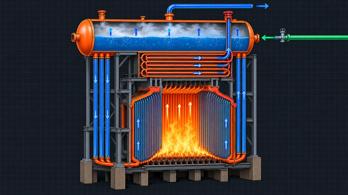
- Section I is a construction code: it governs design, fabrication, examination, testing and stamping of new power boilers, not their operation or in-service repair.
- Steam boilers above 15 psig (103 kPa), and high-temperature water boilers above 160 psig (1,100 kPa) and/or 250 °F (121 °C), fall under Section I. Lower-pressure heating boilers fall under Section IV.
- Boiler external piping up to the valves required by Section I is under Section I administrative jurisdiction, while ASME B31.1 supplies its technical rules.
- Materials come from Section II, welding qualification from Section IX and examination methods from Section V.
- The minimum hydrostatic test pressure is 1.5 times the maximum allowable working pressure (MAWP), and safety valves must limit pressure to no more than 6% above MAWP.
- Designators such as S, A, PP, M, E, V and PRT show which scope an ASME Certificate of Authorization covers.
What Is ASME Section I?
ASME Section I is the construction code that sets mandatory rules for the design, materials, fabrication, inspection and certification of power boilers and related pressure parts. It is part of the ASME Boiler and Pressure Vessel Code (BPVC), published by the American Society of Mechanical Engineers (ASME) and revised on a two-year cycle.
ASME formed its Boiler and Pressure Vessel Committee in 1911 to write standard rules for steam boiler construction. Section I grew out of that effort and still follows the same purpose: keeping steam pressure contained safely.
Section I is largely a design-by-rule code. You calculate required thicknesses with formulas and tabulated allowable stresses instead of performing a full stress analysis. Because the code covers construction only, in-service inspection, repair and alteration fall under the National Board Inspection Code (NBIC), published by the National Board of Boiler and Pressure Vessel Inspectors.
Which Equipment Do ASME Section I Power Boilers Cover?
Section I applies to steam boilers operating above 15 psig (103 kPa) and to high-temperature water boilers above 160 psig (1,100 kPa) and/or 250 °F (121 °C). Its preamble lists power boilers, electric boilers, miniature boilers, high-temperature water boilers, heat recovery steam generators (HRSGs) and certain fired pressure vessels.
Superheaters, economizers and other pressure parts connected directly to the boiler without intervening valves are also within Section I. Typical users include utility and industrial power plants, combined-cycle plants with HRSGs, process steam plants in refineries and chemical complexes, and biomass or waste-to-energy boilers.
| Code | Covers | Typical limits | Designator |
|---|---|---|---|
| BPVC Section I | Power, electric, miniature and high-temperature water boilers, HRSGs, certain fired pressure vessels | Steam above 15 psig (103 kPa); water above 160 psig (1,100 kPa) and/or 250 °F (121 °C) | S, A, PP, M, E, V, PRT |
| BPVC Section IV | Heating boilers | Steam up to 15 psig (103 kPa); hot water up to 160 psig (1,100 kPa) and 250 °F (121 °C) | H |
| BPVC Section VIII Div. 1 | Unfired pressure vessels | Pressure above 15 psig (103 kPa) | U |
| ASME B31.1 | Power piping beyond the boiler boundary, plus technical rules for boiler external piping | Set by design pressure and temperature | None (the PP designator is issued under Section I) |
The pressure and temperature limits decide which section applies. If you are comparing the vessel side of the Code, our guide to ASME Section VIII Division 2 versus Division 1 shows how those design rules differ from the rules for boilers.
Where Does the Boiler End and Boiler External Piping Begin?
Boiler external piping (BEP) is the piping that connects the boiler proper to the first valve or valves required by Section I. The boiler proper means the drums, headers, tubes, superheaters and other pressure parts that generate and contain steam. Piping beyond the required valves is outside the scope of Section I.
The split of responsibility is the part engineers most often misread. Section I holds administrative jurisdiction over BEP, which covers certification by stamping (the PP designator), Manufacturer’s Data Reports and authorized inspection. ASME B31.1 supplies the technical rules for BEP design, materials and examination, and covers all non-boiler external piping.
- Main steam: from the superheater or drum outlet to the required stop valve or valves.
- Feedwater: from the boiler to the required stop valve and check valve.
- Blowoff and drain: from the boiler to the required blowoff or drain valves.
The number and position of required valves depend on boiler type, pressure and the number of boilers on a common header. Check PG-58 and the figures it references for your configuration.
On project drawings, mark the BEP boundary on P&IDs and isometrics. That way the PP certificate holder, the boiler manufacturer and the Authorized Inspector agree where Section I paperwork ends.
How Is ASME Section I Organized?
Section I is organized into Parts, one for general requirements and others for each construction method or boiler type. Part PG applies to every boiler, and the other Parts add rules for a specific method or equipment type.
| Part | Subject |
|---|---|
| PG | General requirements for all methods of construction, including materials, design formulas, openings, safety valves, hydrostatic test, inspection and marking |
| PW | Boilers fabricated by welding |
| PR | Boilers fabricated by riveting |
| PB | Boilers fabricated by brazing |
| PFT | Firetube boilers |
| PWT | Watertube boilers |
| PEB | Electric boilers |
| PMB | Miniature boilers |
| PL | Locomotive boilers |
| PVG | Organic fluid vaporizers |
| PHRSG | Heat recovery steam generators |
- BPVC Section II: Part A (ferrous materials), Part B (nonferrous materials), Part C (welding rods, electrodes and filler metals) and Part D (properties, including allowable stresses).
- BPVC Section V: nondestructive examination methods.
- BPVC Section IX: welding, brazing and fusing qualifications.
- ASME B31.1: technical rules for boiler external piping and all power piping.
- ASME QAI-1: qualifications for Authorized Inspectors.
- NBIC: in-service inspection, repair and alteration after construction.
How Are Pressure Parts Designed Under Section I?
Pressure parts are designed by calculating a minimum required thickness from the design pressure, the allowable stress at design temperature and a set of coefficients. The main formulas sit in PG-27 for tubes, pipes, drums and headers under internal pressure.
Which Materials and Allowable Stresses Does Section I Use?
Material that carries pressure must be permitted by Section I and conform to a Section II specification (PG-5). Allowable stress values come from Section II Part D: Table 1A for ferrous materials and Table 1B for nonferrous materials, read at the design metal temperature. For base-metal groupings used in welding, see our P-Number and F-Number grouping guide.
At high metal temperatures the allowable stress is controlled by time-dependent behavior, so the values rest on creep rupture test data. That is why creep-strength-enhanced steels such as 9Cr-1Mo-V are common in modern boilers; our P91 welding requirements guide covers the fabrication side.
How Is Minimum Wall Thickness Calculated?
Two PG-27 equations cover most pressure parts. Tubes use the first equation and pipes, drums and headers use the second. Apply both within the limits stated in PG-27 for your edition.
Worked example: seamless steel header pipe
The inputs below are stated for illustration. Take the real allowable stress S from Section II Part D for your material and temperature.
Ordering by minimum wall removes Step 4. For a quick Barlow-based estimate of what a given pipe can withstand, you can use our burst pressure calculator, but remember that Barlow’s formula is not a Section I design equation.
What Welding, Heat Treatment and Examination Rules Apply?
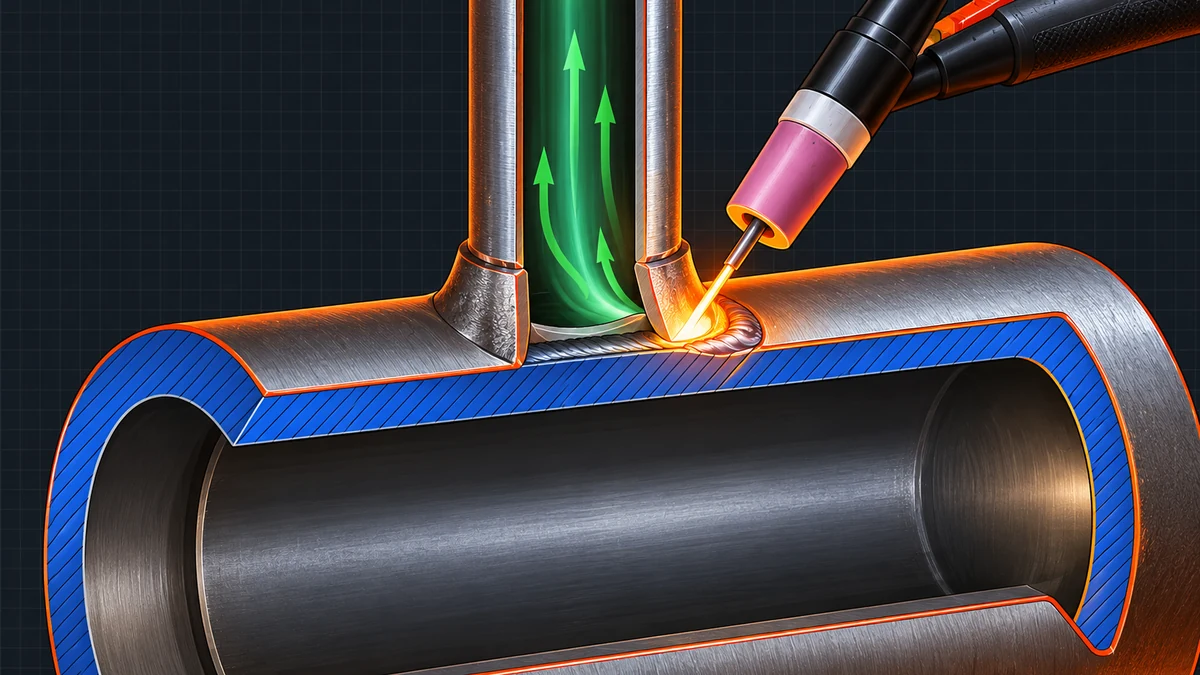
Part PW sets the welded-construction rules, while Section IX supplies the qualification rules. Welding procedures and welders must be qualified to Section IX, and the manufacturer stays responsible for both. To see how procedure variables are controlled, read our guide to QW-200 WPS variables and the Article IV welder qualification rules.
| Topic | Summary of the requirement | Where to verify |
|---|---|---|
| Procedures and welders | Welding procedures and welders are qualified to Section IX; the manufacturer is responsible for both | Part PW; Section IX |
| Post-weld heat treatment (PWHT) | Required above material-dependent thickness limits; for carbon steel P-No. 1 generally above 3/4 in (19 mm) nominal thickness, normally 595 °C (1,100 °F) minimum with 1 hour per inch (25 mm) and a 15 minute minimum | PW-39 |
| Volumetric examination | Radiographic (RT) or ultrasonic (UT) examination of butt welds in drums, shells, headers and larger or thicker pipes; exemptions depend on size, thickness and material | PW-11; Section V |
| Defect repair | Defects are removed and repaired with qualified procedures, then re-examined | Part PW |
| Records | Examination, PWHT and test records support the Manufacturer’s Data Report | Part PG; Data Report forms |
How Does PWHT Work for Boiler Parts?
PWHT relieves residual stress and tempers weld and heat-affected zone microstructure after welding. Section I ties the requirement to the material P-Number and the thickness at the weld. Alloy steels such as Cr-Mo grades carry stricter rules than carbon steel, so check the tables for your P-Number. You can plan hold times with our PWHT soak time calculator and then confirm them against PW-39 for your edition.
Which Examination Method Should You Choose?
Section I names the weld joints that need volumetric examination, and Section V defines how RT and UT are performed. Where the Code allows a choice, the decision depends on thickness, access and the defects you need to find. Our NDT method selection guide compares RT, UT and related methods.
Authorized Inspectors typically review WPS and PQR coverage, welder qualification and continuity records, filler metal traceability, preheat and interpass records, PWHT charts and NDE reports before the hydrostatic test is scheduled. Missing records are a more common cause of delay than weld quality.
How Is a Boiler Tested and Protected Against Overpressure?
A completed boiler is hydrostatically tested to at least 1.5 times the maximum allowable working pressure (MAWP), as required by PG-99. Overpressure in service is limited by safety valves selected under PG-67 and related rules, which keep pressure within 6% of MAWP during relief.
What Is the Hydrostatic Test Pressure?
The test is witnessed by the Authorized Inspector, and joints are examined for leakage. Safety valves are removed or held to their seats with test clamps as the Code allows. For a comparison of liquid and gas testing under other ASME codes, see our guide to hydrostatic versus pneumatic pressure testing.
What Are the Safety Valve Requirements?
- Each boiler needs at least one safety valve. Two or more are required when the boiler has more than 500 ft² (46 m²) of bare tube water-heating surface, or an electric boiler exceeds 1,100 kW input.
- At least one valve on the boiler proper is set at or below MAWP.
- The valves must discharge all the steam the boiler can generate without letting pressure rise more than 6% above MAWP.
- Valves carry the V designator, showing that they were built under an ASME certificate.
Who Certifies and Inspects Section I Boilers?
A manufacturer needs an ASME Certificate of Authorization for the relevant scope before applying the ASME Certification Mark, and an Authorized Inspector verifies the work. The Certification Mark appears with a designator that shows the scope of the certificate. ASME publishes the certificate scopes in its BPV certificate scopes guide (BPV-GUI-02).
| Designator | Scope |
|---|---|
| S | Power boilers |
| A | Assembly of power boilers |
| PP | Pressure piping, including boiler external piping |
| M | Miniature boilers |
| E | Electric boilers |
| V | Safety valves and safety relief valves |
| PRT | Fabrication of parts without design responsibility |
How Does a Manufacturer Get Authorized and Certify a Boiler?
- Build the quality control system. The manufacturer writes a quality control system that meets the Section I requirements and defines how design, materials, welding, examination and records are controlled.
- Engage an Authorized Inspection Agency. The manufacturer contracts an Authorized Inspection Agency (AIA) whose Authorized Inspector will verify work at the shop and, where applicable, in the field.
- Pass the joint review. ASME arranges a review of the quality control system and its implementation, normally with the jurisdiction and the AIA, before issuing a Certificate of Authorization.
- Control materials and welding. Materials are purchased to Section II specifications with traceable test reports, and welding procedures and welders are qualified to Section IX before production welding.
- Examine and heat treat. Production welds receive the visual, volumetric and surface examinations and the post-weld heat treatment that Section I requires, and records are kept.
- Test under the Authorized Inspector. The completed boiler or part is hydrostatically tested to at least 1.5 times the maximum allowable working pressure (MAWP) with the Authorized Inspector present.
- Complete the data report and mark. The manufacturer completes the Manufacturer’s Data Report, the Authorized Inspector signs it, and the ASME Certification Mark with its designator is applied.
The Authorized Inspector is qualified under ASME QAI-1 and works for the AIA. That role is separate from a client or third-party inspector, whose duties are described in our guide to third party inspection in welding. Many projects use both, and one does not replace the other.
Does ASME Section I Compliance Satisfy Local Regulations?
Code compliance and legal approval are separate matters. Many US states and Canadian provinces make the ASME boiler rules legally mandatory, while in other countries regulators or contract specifications decide how the code is accepted.
Boiler design, manufacture, registration and inspection in India have been regulated under the Boilers Act, 1923 and the Indian Boiler Regulations, 1950. Parliament has since passed the Boilers Bill, 2024 to replace the 1923 Act. An ASME Section I stamp does not by itself give statutory approval, so confirm the currently applicable rules and the approval route with the Central Boilers Board or the Chief Inspector of Boilers of the relevant state before you commit to a design basis.
Quick Reference: Section I Numbers at a Glance
This cheat sheet collects the values used most often in boiler specifications. Verify each against the edition and contract that apply to your project.
| Parameter | Typical Section I value | Where to verify |
|---|---|---|
| Steam boiler scope | Above 15 psig (103 kPa) | Preamble; Part PG |
| High-temperature water scope | Above 160 psig (1,100 kPa) and/or 250 °F (121 °C) | Preamble; Part PG |
| Allowable stress source | Section II Part D, Table 1A (ferrous) and 1B (nonferrous) | Section II Part D |
| Tube thickness | t = PD/(2S + P) + 0.005D + e | PG-27 |
| Pipe and header thickness | t = PD/(2SE + 2yP) + C | PG-27 |
| y coefficient, ferritic steel | 0.4 up to 900 °F (482 °C) | PG-27 |
| PWHT trigger, carbon steel P-No. 1 | Above 3/4 in (19 mm) nominal thickness | PW-39 |
| Minimum hydrostatic test | 1.5 x MAWP | PG-99 |
| Safety valve accumulation | Not more than 6% above MAWP | PG-67 |
| Number of safety valves | One minimum; two or more above 500 ft² (46 m²) or 1,100 kW electric | PG-67 |
| Certificate designators | S, A, PP, M, E, V, PRT | ASME BPV-GUI-02 |
What Are the Common Mistakes and Limits?
Most Section I problems come from boundary confusion, edition control and missing documentation, not from the formulas themselves. The points below are the ones that most often cause rework or rejected data reports.
- Treating Section I and B31.1 as interchangeable. The two codes meet at the BEP boundary but carry different responsibilities, so each part of the system must be assigned to the right code.
- Using Section VIII Division 1 rules for a steam boiler. The design rules, test factors and certification marks differ.
- Applying another code’s allowable stress tables. Use the Section II Part D values and criteria that Section I references for your edition.
- Skipping exemption checks. PWHT and volumetric examination exemptions depend on thickness, size and material, and an assumed exemption is a common audit finding.
- Assuming Section I covers operation and repair. It stops at new construction; the NBIC and local rules govern the boiler afterward.
- Confusing the Authorized Inspector with the client inspector. Each has separate authority and neither replaces the other.
Requirements depend on the code edition, addenda and contract specification applicable to your project. Section I is a design-by-rule code, so unusual geometry, cyclic duty or severe high-temperature service may need engineering analysis beyond the rules summarized here.
Frequently Asked Questions
What is ASME Section I used for?
ASME Section I is used to construct power boilers, high-temperature water boilers, electric boilers, miniature boilers and heat recovery steam generators. It sets the rules for materials, design, welding, examination, hydrostatic testing, safety valves, marking and inspection. A manufacturer must hold an ASME Certificate of Authorization before applying the Certification Mark. The code does not cover operation or later repair of the boiler.
What is the difference between ASME Section I and Section VIII Division 1?
Section I covers steam boilers and their pressure parts, while Section VIII Division 1 covers unfired pressure vessels. The two codes use different design rules, test factors and certification marks. A boiler is marked with the S designator under Section I, and a vessel is marked with the U designator under Section VIII. For example, the minimum Section I hydrostatic test is 1.5 times MAWP, whereas Division 1 uses 1.3 times MAWP adjusted by a stress ratio.
What is the difference between ASME Section I and ASME Section IV?
Section IV covers heating boilers, which are steam boilers up to 15 psig (103 kPa) and hot-water boilers up to 160 psig (1,100 kPa) and 250 °F (121 °C). Section I covers boilers above those limits. Section IV boilers carry the H designator, while Section I power boilers carry the S designator. The operating pressure and temperature limits decide which section applies.
What is boiler external piping and which code governs it?
Boiler external piping (BEP) is the piping that connects the boiler proper to the first valve or valves required by Section I, such as main steam, feedwater, blowoff and drain lines. Section I holds administrative jurisdiction over BEP, which includes certification, data reports and authorized inspection. ASME B31.1 provides the technical rules for BEP design, materials and examination. Piping beyond the required valves is outside Section I, and our guide to B31.1 versus B31.3 piping requirements explains how the piping codes divide the work.
What is the hydrostatic test pressure for a Section I boiler?
Section I requires a hydrostatic test of at least 1.5 times the maximum allowable working pressure (MAWP), under PG-99. A boiler with a 9.0 MPa (1,305 psi) MAWP is therefore tested at 13.5 MPa (1,958 psi) or more. The Authorized Inspector witnesses the test, and the joints are examined for leakage. Other ASME codes use different multipliers, so compare them in our guide to hydrostatic and pneumatic test rules.
Which ASME designator does a power boiler manufacturer need?
A manufacturer of a complete power boiler needs the S designator, shown with the ASME Certification Mark. The A designator covers assembly of power boilers, PP covers pressure piping, E covers electric boilers, M covers miniature boilers and V covers safety valves. The PRT designator covers fabrication of parts without design responsibility. Each designator needs its own ASME Certificate of Authorization with a stated scope.
Does ASME Section I cover repairs and operation of boilers?
No. Section I is a construction code, so it applies to new construction up to certification and delivery. In-service inspection, repairs and alterations are covered by the National Board Inspection Code (NBIC), and operation is governed by the owner’s procedures and local regulations. Repair organizations typically need the appropriate National Board repair authorization. Always check which rules the local jurisdiction applies to an existing boiler.
Key Terms
- Power boiler
- A boiler that generates steam above 15 psig (103 kPa) for use outside itself and is built under Section I.
- Boiler proper
- The drums, headers, tubes, superheaters and other pressure parts that generate and contain steam up to the Section I boundary.
- Boiler external piping (BEP)
- Piping that connects the boiler proper to the first valve or valves required by Section I.
- Maximum allowable working pressure (MAWP)
- The highest gauge pressure at which a boiler or boiler part is permitted to operate under the Code design rules.
- Authorized Inspector (AI)
- A person qualified under ASME QAI-1 and employed by an Authorized Inspection Agency who verifies that construction complies with the Code.
- Certificate of Authorization
- The ASME document that permits a manufacturer to apply the Certification Mark for a stated scope.
- Heat recovery steam generator (HRSG)
- A boiler that generates steam from the heat of hot exhaust gas, such as gas turbine exhaust.
Conclusion
ASME Section I power boilers follow a single construction code from design through hydrostatic test and certification. Remember the anchor points: scope starts above 15 psig steam, the BEP boundary sits at the valves required by Section I, materials come from Section II, qualification comes from Section IX, the hydrostatic test is at least 1.5 times MAWP and safety valves hold pressure within 6% of MAWP. Always work to the edition and addenda named in your contract, because limits and clause numbers can change between editions. As a next step, test your grasp of the welding qualification rules that Section I relies on with our ASME Section IX practice quiz.
This guide was prepared by the WeldFabWorld technical team from the standards listed in Standards and References. Verify every requirement against the code edition and specification applicable to your project.
Standards and References
- ASME BPVC Section I, Rules for Construction of Power Boilers, ASME
- ASME BPVC Section II, Materials, Parts A, B, C and D, ASME
- ASME BPVC Section IV, Rules for Construction of Heating Boilers, ASME
- ASME BPVC Section V, Nondestructive Examination, ASME
- ASME BPVC Section VIII Division 1, Rules for Construction of Pressure Vessels, ASME
- ASME BPVC Section IX, Welding, Brazing, and Fusing Qualifications, ASME
- ASME B31.1, Power Piping, ASME
- ASME QAI-1, Qualifications for Authorized Inspection, ASME
- NB-23, National Board Inspection Code, National Board of Boiler and Pressure Vessel Inspectors
- Boilers Act, 1923; Indian Boiler Regulations, 1950; Boilers Bill, 2024, Government of India