Erosion-Corrosion in Piping Systems
Erosion-corrosion in piping systems shows up almost exactly where an engineer would predict it will once they know what to look for: the outer radius of elbows, immediately downstream of valves and orifices, at reducers and tees, and — a detail fabrication teams sometimes miss — right at a poorly fitted weld root. It is a combined mechanical and electrochemical mechanism, and that combination is what makes it more aggressive than either erosion or corrosion would be acting alone, since each process continuously strips away the protection the other would otherwise rely on.
This guide covers the erosion-corrosion mechanism, the specific forms it takes (impingement, cavitation, slurry erosion), the erosional velocity concept used to screen piping designs, the weld-related factors that create localized attack points, and the design, material, and inspection practices used to control it. For pressure design and erosion allowance calculation in piping wall thickness, see the pipe wall thickness calculator and the ASME B31.3 process piping guide.
The Erosion-Corrosion Mechanism
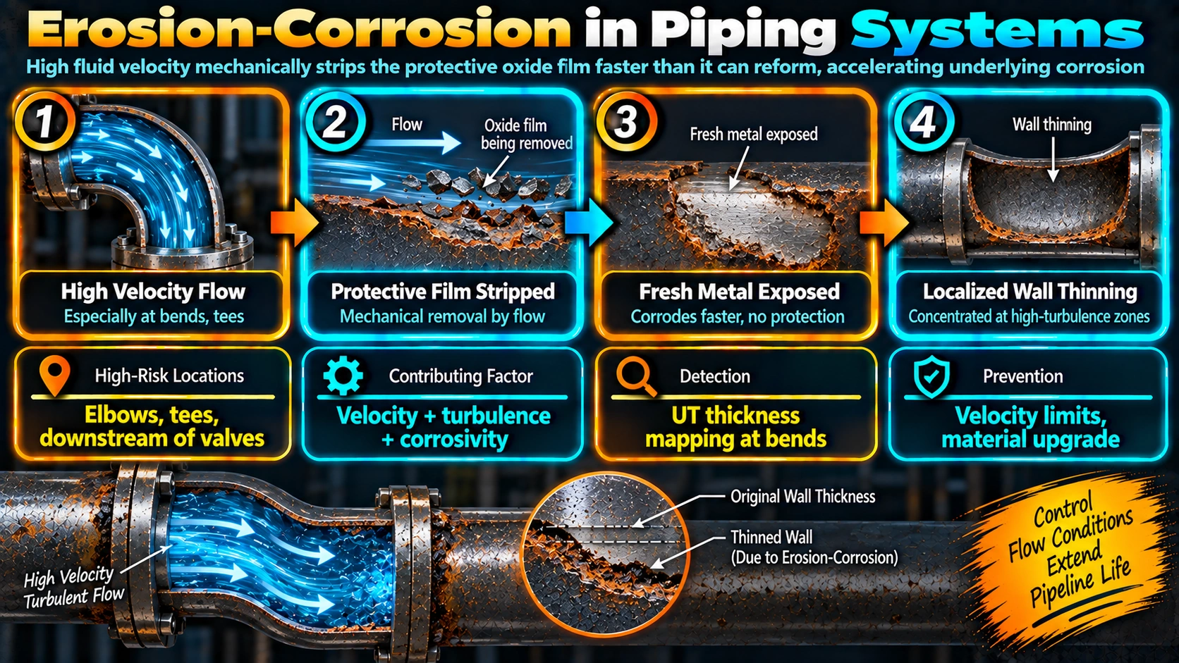
Erosion-corrosion is the synergistic combination of mechanical material removal and electrochemical corrosion, and the synergy is the key point: flowing fluid — especially fluid carrying solid particles, gas bubbles, or moving at high velocity — continuously removes the protective oxide film or corrosion product layer that would otherwise slow further chemical attack. Each time that protective layer is stripped, fresh, unprotected metal is exposed to the corrosive environment, which then corrodes at an accelerated rate until a new protective layer can form, only for the cycle to repeat. The combined damage rate is typically far higher than the sum of erosion alone plus corrosion alone would predict on the same material and environment.
Impingement Attack
Impingement attack occurs where flow direction changes force fluid, solid particles, or liquid droplets to strike the pipe wall directly rather than following the bulk streamlines — the classic condition at elbows, tees, and reducers.
Cavitation Damage
Cavitation occurs when local pressure drops below the fluid’s vapor pressure, forming vapor bubbles that then collapse violently as pressure recovers downstream, generating intense localized micro-jet impacts. It is most common downstream of control valves, pump impellers, and orifice plates, and is generally grouped with erosion-corrosion because the mechanical damage mechanism and resulting film disruption are functionally similar.
Slurry and Particulate Erosion
Solids-laden flow — sand production in oil and gas, catalyst fines in refining, ash in power plant service — adds direct particle impact to the mechanism, and damage severity scales strongly with particle hardness, concentration, and velocity.
Erosional Velocity: A Design Screening Tool
API RP 14E provides a widely used empirical formula for estimating the maximum recommended flow velocity before erosion-corrosion becomes a significant design concern:
Weld-Related Contributing Factors
Fabrication quality directly affects local erosion-corrosion risk, independent of the bulk design velocity:
- Weld root protrusion into the bore creates a local flow obstruction and turbulence point, behaving like a miniature elbow effect even in an otherwise straight run.
- High-low misalignment between pipe ends at a butt weld creates a step in the ID that disturbs flow locally.
- Unremoved weld spatter or icicles projecting into the bore act as direct impingement targets for particle-laden or high-velocity flow.
- Backing rings left in place present both a crevice corrosion site and a flow obstruction — see the crevice corrosion guide for the crevice half of that risk.
Controlling internal weld profile through correct joint fit-up, appropriate welding technique, and — where warranted — internal grinding or ID bore inspection on erosion-critical lines addresses a risk factor that pure material selection cannot fix on its own. See the butt weld vs socket weld fittings guide for how joint type selection itself affects both crevice and erosion risk at small-bore connections.
Recognising Erosion-Corrosion Damage
| Feature | Erosion-Corrosion | General/Uniform Corrosion |
|---|---|---|
| Damage pattern | Directional grooving, horseshoe-shaped pits aligned with flow | Roughly uniform metal loss over the exposed surface |
| Location | Elbows, tees, downstream of valves, weld roots — highly localised | Distributed across the exposed surface |
| Predictability | Predictable from flow geometry and velocity | Predictable from bulk environment exposure |
| Primary detection method | UT thickness mapping at known high-risk points | General UT survey or corrosion coupons |
Design and Material Prevention Strategies
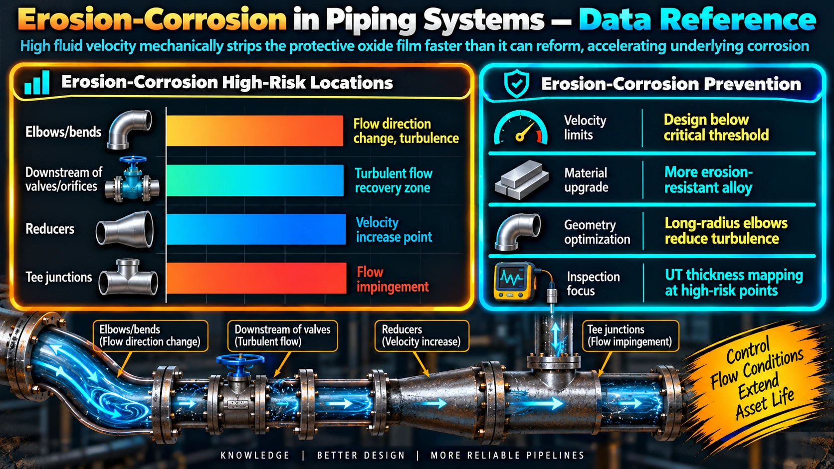
- Increase pipe diameter to reduce velocity below the applicable erosional velocity limit for a given flow rate.
- Use long-radius elbows rather than short-radius or mitered bends to reduce local turbulence and impingement angle.
- Specify heavier-wall fittings (erosion allowance) at elbows, tees, and reducers rather than uniformly upsizing the entire line — see the elbow weight calculator for sizing heavy-wall fittings.
- Select higher-C-factor materials (corrosion-resistant alloys, duplex stainless) for elevated velocity or solids-bearing service, recognising this raises the erosional velocity limit but does not eliminate mechanical erosion at severe conditions.
- Maintain adequate NPSH margin on pump suction to avoid cavitation, and avoid unnecessary pressure drop concentrated at a single restriction.
- Control internal weld quality — fit-up, root profile, and spatter removal — on erosion-critical lines.
- Filter or settle out solids upstream where practical, reducing particulate loading at high-risk fittings.
Frequently Asked Questions
What is the difference between erosion-corrosion and simple mechanical erosion?
Simple mechanical erosion is pure material removal by physical impact, such as sand blasting a surface, and can occur even on a completely inert material. Erosion-corrosion is the combined and synergistic effect of mechanical action and electrochemical corrosion, where flowing fluid continuously strips away the protective oxide film or corrosion product layer that would otherwise slow further attack, repeatedly exposing fresh, unprotected metal to the corrosive environment. The combined damage rate in erosion-corrosion is typically much higher than the sum of erosion alone plus corrosion alone would predict, because each mechanism accelerates the other.
What is erosional velocity and how is it calculated?
Erosional velocity is the maximum recommended fluid velocity in piping above which erosion-corrosion damage becomes a significant concern. API RP 14E provides a widely used empirical formula, Ve = C / sqrt(rho), where Ve is erosional velocity in ft/s, rho is fluid density in lb/ft3, and C is an empirical constant that depends on service conditions — typically 100 for continuous service with solids present, and up to 300 for corrosion-resistant alloys in clean, non-corrosive, solids-free service. This is a screening guideline, not a precise damage prediction, and site-specific erosion modelling is used for critical or borderline cases.
Why do pipe elbows and tees suffer erosion-corrosion more than straight runs?
Elbows and tees force the flow to change direction, which increases local turbulence and wall shear stress on the outer radius of the bend, and in two-phase or particulate-laden flow, causes solid particles or liquid droplets to impinge directly on the pipe wall rather than following the streamlines. This combination of elevated shear stress and direct impingement strips protective films faster than a straight run experiences under the same bulk flow conditions, which is why elbows, tees, and reducers are consistently the highest-risk locations for erosion-corrosion in piping systems.
Can a poorly fitted weld root cause erosion-corrosion inside a pipe?
Yes. Internal weld root protrusion, high-low misalignment between pipe ends, weld spatter, or icicles projecting into the bore all create local flow disturbance and turbulence at that specific point, even in an otherwise straight pipe run. That localized turbulence behaves like a miniature version of the elbow effect, accelerating local erosion-corrosion at and just downstream of the weld even though the surrounding pipe experiences normal, lower-risk flow conditions — which is one reason internal weld quality control matters as much for corrosion performance as for structural integrity in erosion-prone services.
What is cavitation damage and how does it relate to erosion-corrosion?
Cavitation occurs when local pressure drops below the fluid’s vapor pressure, forming vapor bubbles that then collapse violently when they reach a higher-pressure region downstream, generating intense, localized micro-jet impacts on the metal surface. This mechanical damage strips protective films and roughens the surface in the same way particle impingement does, so cavitation-driven material loss is generally classified alongside erosion-corrosion, and it is most commonly seen downstream of control valves, pump impellers, and orifice plates where a sharp pressure drop occurs.
Does upgrading to a corrosion-resistant alloy always solve an erosion-corrosion problem?
Not on its own. A more corrosion-resistant alloy has a higher C-factor and therefore a higher erosional velocity limit, giving more margin, but if the underlying flow velocity, turbulence, or particle loading is severe enough, even highly alloyed materials can still erode mechanically — erosion-corrosion has a mechanical component that pure corrosion resistance does not address. Design changes (larger diameter to reduce velocity, streamlined fittings, flow straighteners) and operational controls (solids filtration, cavitation avoidance) are usually needed alongside, not instead of, material upgrades.
How is erosion-corrosion damage recognised during inspection?
Erosion-corrosion typically produces directional damage patterns aligned with flow — grooving, scalloping, and horseshoe-shaped pits pointing in the flow direction — concentrated at predictable high-risk locations such as the outer radius of elbows, downstream of valves and orifices, and at weld root protrusions, rather than the random distribution typical of general pitting. Ultrasonic thickness mapping at these specific high-risk locations, tracked over time as part of a risk-based inspection program, is the standard method for monitoring wall loss progression.
What is an erosion allowance and how does it relate to pipe wall thickness design?
Erosion allowance is additional wall thickness added on top of the pressure design thickness and corrosion allowance specifically to account for expected material loss from erosion or erosion-corrosion over the design life, determined by the process engineer based on expected particle size, velocity, and fluid phase per codes such as ASME B31.3. It is applied at the specific locations expected to see elevated erosion risk — elbows, tees, reducers — often through the use of heavier-wall fittings at those locations rather than uniformly increasing wall thickness across the entire piping system. See the pipe wall thickness calculator for the full B31.3 formula.
Recommended Reading
Corrosion Engineering (Fontana)
Classic reference covering erosion-corrosion, cavitation damage, and flow-related corrosion mechanisms.
View on AmazonAPI RP 14E Recommended Practice
The source standard for erosional velocity screening in oil and gas piping design.
View on AmazonASM Handbook Vol. 13: Corrosion
Reference-grade coverage of erosion-corrosion, cavitation, and flow-accelerated corrosion mechanisms.
View on AmazonPiping Handbook (Nayyar)
Comprehensive piping design reference including erosion allowance, fitting selection, and flow-related design practice.
View on AmazonDisclosure: WeldFabWorld participates in the Amazon Associates programme (StoreID: neha0fe8-21). If you purchase through these links, we may earn a small commission at no extra cost to you. This helps support free technical content on this site.