Yield Strength vs Tensile Strength: What Welders Need to Know
Every mill certificate reports both yield strength and tensile strength, and most welders can recite the textbook definitions without hesitation — yield is where permanent deformation starts, tensile (UTS) is the maximum stress before fracture. What matters far more for a real WPS or joint design decision is the relationship between the two: the yield-to-tensile ratio, and what that ratio implies for filler metal selection, code allowable stress, and how a joint will actually behave under overload. That relationship, not the definitions themselves, is what this article covers.
For the full definitions, the stress-strain curve, and the 0.2% offset method used for materials without a distinct yield point, see the mechanical properties of metals guide and the stress-strain curve guide — this article assumes that foundation and goes straight to the welding decisions the yield/tensile relationship actually drives.
The Yield-to-Tensile (Y/T) Ratio
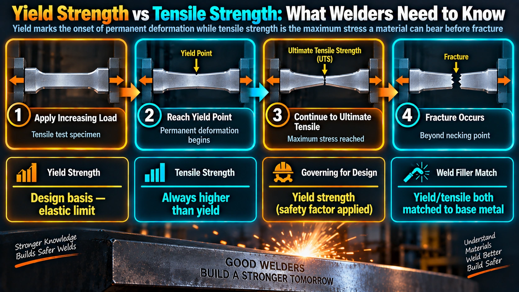
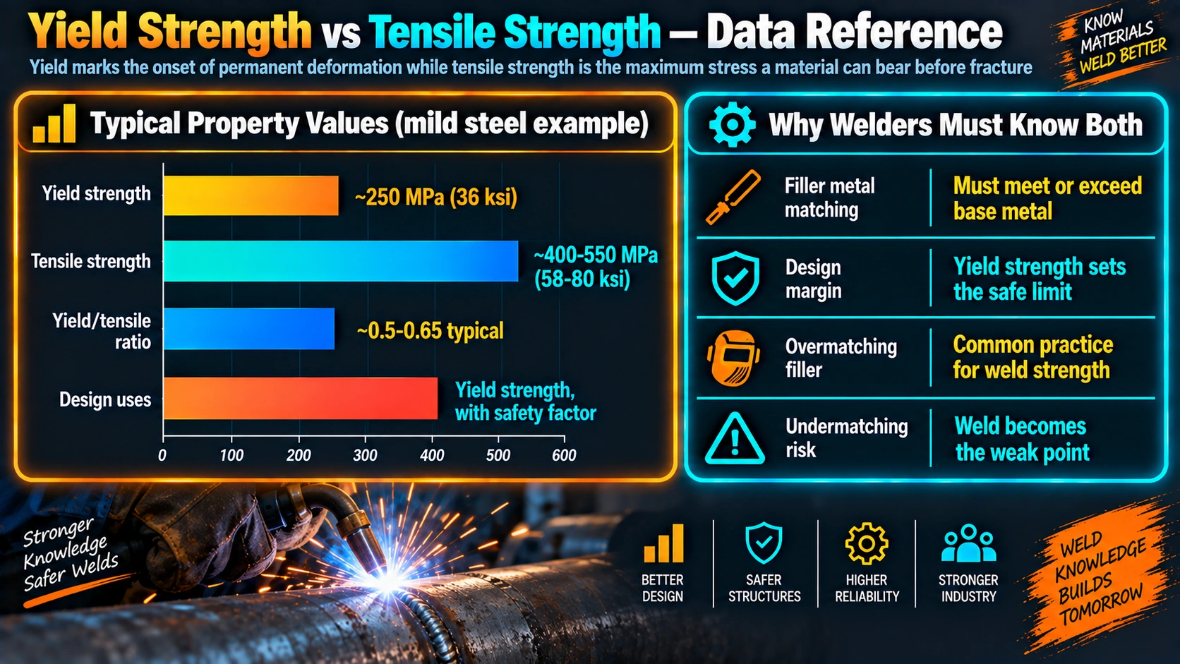
The Y/T ratio is simply yield strength divided by ultimate tensile strength, and it is a far more useful design indicator on its own than either number alone, because it describes how much reserve capacity a material has between the onset of yielding and outright fracture.
| Steel Type | Typical Y/T Ratio | Practical Implication |
|---|---|---|
| Mild / carbon steel (A36-type) | ~0.5-0.6 | Large reserve capacity, highly ductile failure mode |
| HSLA structural steel | ~0.8-0.85 | Moderate reserve; still generally acceptable for most static design |
| Quenched & tempered high-strength steel | ~0.85-0.95 | Limited reserve; ductility and toughness become more critical design considerations |
| Some advanced high-strength steels | Approaching 1.0 | Minimal reserve; fracture-critical design requires careful joint detailing |
Filler Metal Matching Strategy
The base metal’s yield and tensile strength, and its Y/T ratio, directly inform how filler metal strength is selected relative to the base metal.
Matching Filler
Filler metal with yield and tensile strength close to the base metal is the default approach specified for most structural steel welding under AWS D1.1, giving a joint whose overall capacity closely tracks the base metal’s rated strength.
Undermatching
Deliberately using a filler with lower strength than the base metal, but with better ductility and toughness, is an accepted approach on some high-strength quenched and tempered steels specifically to keep the weld metal from being the most brittle, most crack-susceptible part of the joint — forcing any yielding under overload into the more ductile weld rather than risking a harder, more crack-prone zone reaching its limit first.
Overmatching
Deliberately using a filler stronger than the base metal is standard in pipeline girth welds under strain-based design (API 1104) and other fatigue or fracture-critical joints, specifically to ensure that when the joint is strained, plastic deformation concentrates in the base metal — where ductility is well-characterized along the pipe body — rather than in the weld metal or HAZ, where geometric and metallurgical variability make deformation behavior harder to predict.
How Codes Reference Yield vs. Tensile Differently
Allowable stress design for pressure vessels and structures — ASME Section VIII, AISC — is built around avoiding permanent deformation in normal service, so it references yield strength (commonly two-thirds of yield, or the lower of a yield-based and a UTS-based value) with a built-in safety margin, since yielding is the practical serviceability limit for most equipment. Some specific joint capacity formulas instead reference ultimate tensile strength directly — the fillet weld strength calculator uses base metal UTS with its own empirical shear factor, because that formula is calibrated against the actual shear failure mode observed in testing rather than a general yielding criterion. Knowing which basis a given code check uses, and why, matters more in practice than simply having both numbers on hand.
Reading the Mill Certificate for WPS Decisions
A complete mill test report (MTR/CMTR) reports both yield and tensile strength for the actual heat, and both matter for different reasons: yield strength feeds allowable stress design calculations, tensile strength feeds weld joint capacity checks, and the ratio of the two — calculated from the actual heat-specific values, not just the nominal grade minimums — tells you whether that particular heat behaves closer to a ductile, high-reserve material or a lean, fracture-sensitive one. Two heats of the same nominal grade can report meaningfully different Y/T ratios, which is one more reason a welding engineer should check the actual reported values on the CMTR rather than assuming every heat behaves identically to the specification minimum.
Y/T Ratio and Fatigue-Critical Design
Fatigue-critical welded structures already carry tensile residual stress at the weld toe approaching the base metal’s yield strength — see the residual stress in welded joints guide and fatigue-critical components guide for that mechanism in detail. A high Y/T ratio material has less remaining margin to yield locally and relieve that residual stress through minor plastic accommodation, which can leave more of it intact to act as a mean stress superimposed on cyclic fatigue loading — one more reason Y/T ratio is weighed alongside residual stress and weld toe geometry in fatigue-sensitive design.
Frequently Asked Questions
What does a high yield-to-tensile ratio actually mean for a welded structure?
A high Y/T ratio means the material’s yield strength is close to its ultimate tensile strength, leaving little margin between the onset of permanent deformation and outright fracture. In practical terms, a structure made from high Y/T material gives less visible warning (less plastic deformation) before failure than a low Y/T material would under the same overload condition, which is why codes covering seismic and strain-based pipeline design impose maximum Y/T ratio limits — they want to guarantee a structure yields visibly and absorbs energy before it fractures, not the other way around.
What is the difference between matching, undermatching, and overmatching filler metal?
Matching filler metal has yield and tensile strength close to the base metal, and is the default approach for most structural steel welding per AWS D1.1. Undermatching uses filler metal with lower strength than the base metal, deliberately keeping the weld metal more ductile and tougher than the base metal in some high-strength quenched and tempered steel applications, so that any yielding is forced to occur in the more ductile weld rather than risk cracking in a harder zone. Overmatching uses filler metal stronger than the base metal, commonly specified in pipeline girth welds and other strain-based or fatigue-critical designs specifically to ensure any plastic deformation concentrates in the base metal rather than the weld.
Why do pipeline codes require overmatching filler for strain-based design?
Strain-based pipeline design (used where a pipeline may experience significant ground movement, such as seismic zones or permafrost regions) deliberately allows the pipe to undergo controlled plastic strain without failure. Overmatched girth weld filler metal ensures that when the pipe is strained, deformation concentrates in the base metal, which typically has better-characterized, more uniform ductility along the pipe body, rather than in the weld metal or HAZ, where geometric and metallurgical variability make the deformation behaviour less predictable and more prone to localized strain concentration.
Why does ASME Section VIII allowable stress design use yield strength while some other weld strength calculations reference tensile strength?
Allowable stress design for pressure vessels and structures is built around avoiding permanent deformation in normal service, so it references yield strength (typically two-thirds of yield, or the lower of that and a UTS-based value) with a built-in safety margin, since yielding — not fracture — is the practical serviceability limit for most equipment. Some specific joint capacity calculations, such as fillet weld shear strength formulas, instead reference the base metal’s ultimate tensile strength with their own separate empirical safety factor, because those formulas are calibrated against the actual failure mode observed in shear testing of those specific joint configurations rather than against a general yielding criterion.
Why would a welding engineer choose a weaker (undermatched) filler metal on purpose?
On high-strength quenched and tempered steels, an undermatched filler with lower strength but higher ductility and toughness than the base metal can produce a more reliable joint overall, because it keeps the weld metal itself from being the most brittle, most crack-susceptible part of the joint. This trades some joint tensile capacity for improved resistance to cracking and better toughness in the weld, which is often the more important property in applications where fracture avoidance matters more than matching the base metal’s peak strength exactly.
Does a mill certificate reporting only yield strength give enough information for WPS qualification?
No — a complete mill test report (MTR/CMTR) reports both yield strength and ultimate tensile strength, and a welding engineer needs both to properly evaluate the material: yield strength for allowable stress design calculations, tensile strength for weld joint capacity checks and for calculating the actual Y/T ratio of that specific heat, which can vary from heat to heat within the same nominal grade. Relying on only one value, or on the nominal specification minimum rather than the actual heat-specific reported values, risks missing a heat with an unusually high Y/T ratio that behaves differently than expected in the welded joint.
Can using an overmatched filler ever make a welded joint worse rather than better?
Yes, in certain configurations. If a much stronger weld metal is used on a lower-strength base metal, plastic strain during overload or fatigue loading concentrates in the softer base metal or HAZ rather than distributing more evenly across the joint, which is exactly the intended effect in pipeline strain-based design but can be counterproductive in other joint geometries where it instead promotes premature base metal or HAZ cracking. Filler selection needs to consider the specific joint geometry, loading type (static versus fatigue), and code requirement rather than defaulting to “stronger filler is always better.”
Why does the Y/T ratio matter for fatigue-critical welded structures specifically?
Fatigue-critical structures already carry significant tensile residual stress at the weld toe, often approaching the base metal’s yield strength, as discussed in the WeldFabWorld residual stress and fatigue-critical components guides. A high Y/T ratio material has less remaining margin to yield locally and relieve that residual stress through minor plastic accommodation, which can leave more of the residual stress intact to act as a mean stress superimposed on the cyclic fatigue loading, one of several reasons Y/T ratio is considered alongside residual stress and weld toe geometry in fatigue design decisions.
Recommended Reading
Welding Metallurgy and Weldability (Lippold)
Covers filler metal matching strategy and mechanical property compatibility across base metal and weld systems.
View on AmazonDesign of Welded Structures (Blodgett)
Classic practical reference on weld joint design, allowable stress, and strength considerations for structural welding.
View on AmazonMechanical Metallurgy (Dieter)
Foundational reference on yield, tensile strength, and the mechanics behind the Y/T ratio and ductility.
View on AmazonAPI 1104: Welding of Pipelines and Related Facilities
The code governing pipeline girth weld strength matching and strain-based design requirements.
View on AmazonDisclosure: WeldFabWorld participates in the Amazon Associates programme (StoreID: neha0fe8-21). If you purchase through these links, we may earn a small commission at no extra cost to you. This helps support free technical content on this site.