Coating Breakdown and Failure Analysis: 5 Real-World Case Studies
A field-based walkthrough of how five different coating failures were actually investigated — symptom, evidence, root cause, and the specification change that stopped it happening again.
Coating breakdown failure analysis is the disciplined process of working backward from a defect that has already occurred — blistering, peeling, cracking, chalking — to the specific root cause on that specific asset, using physical evidence rather than assumption. It is a different exercise from simply knowing what a defect looks like. Our coating defects guide catalogs what each failure mode looks like and the general causes typically associated with it; this article picks up where that catalog leaves off, walking through five real investigation scenarios in enough operational detail that you could run the same process on your own asset.
Each case study below follows the same structure: the asset and its service history, the symptom exactly as an inspector would document it in the field, the evidence gathered to distinguish between competing root causes, the conclusion the evidence supported, and the specification change that was implemented afterward. The five scenarios span a buried pipeline, an atmospheric storage tank, an offshore splash-zone structure, a tank lining, and coastal structural steel — deliberately chosen to cover the exposure categories most engineers and QA/QC professionals will encounter across a career.
None of these case studies are drawn from a single named project; they are composite scenarios built from patterns that recur consistently across published failure investigation literature and field inspection practice, presented here to illustrate the investigation method rather than to describe one specific site.
The Failure Investigation Workflow
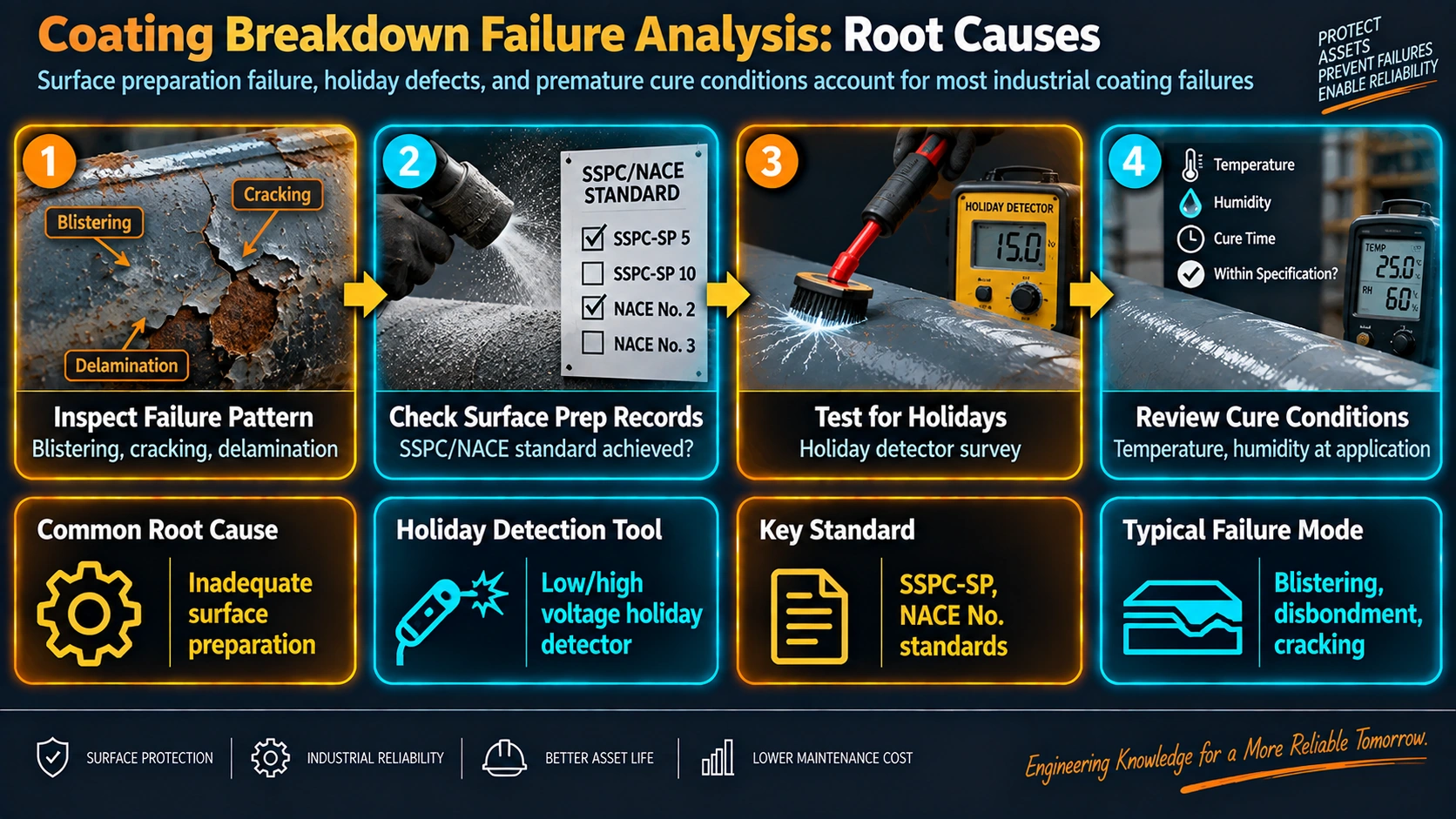
Before the case studies, it is worth setting out the sequence that a defensible coating failure investigation follows. Skipping steps — particularly documentation before disturbance, and cross-section extraction before conclusions — is the most common reason failure reports get challenged during a warranty or liability dispute.
- Document the symptom in place. Photograph the defect at multiple scales, record its location on a marked-up general arrangement drawing, and note the pattern of distribution before any cleaning, sampling, or repair begins. A failure that is isolated to weld seams points somewhere different than one spread uniformly across a flat plate.
- Pull the application and exposure history. DFT logs, environmental readings, batch and lot numbers, coating system data sheets, and the date the asset entered service. A failure investigation without records has to reconstruct this from memory, which is far weaker evidence.
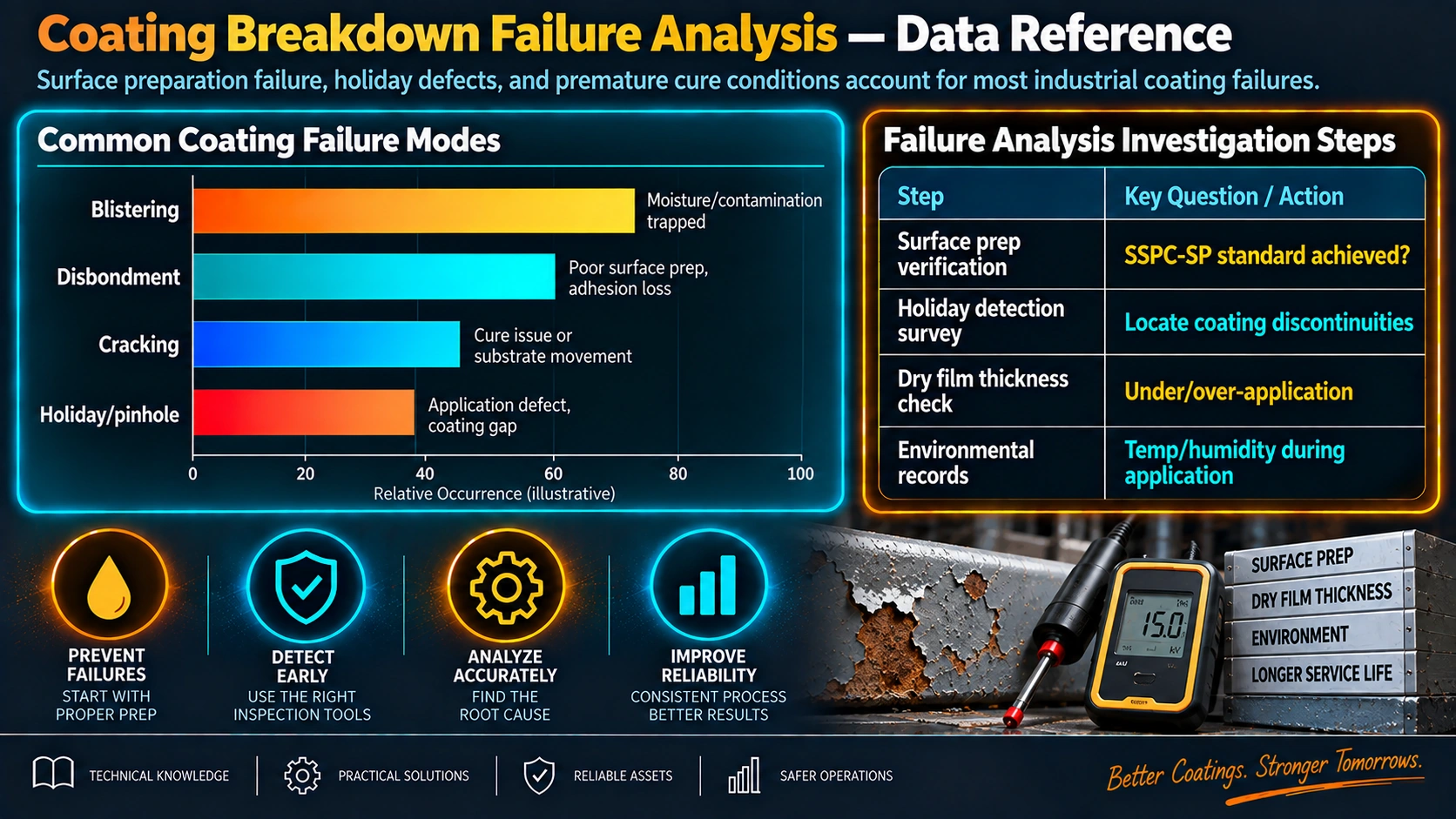
- Run non-destructive testing around the failure site. DFT survey, pull-off adhesion testing both at the failure and on unaffected coating nearby for comparison, and holiday testing where pinholing could be a contributing factor.
- Extract a cross-section coupon. Cut through the coating and into the substrate at the failure site, mount it, and examine it under magnification to identify exactly which interface has separated and what the actual film thickness was at that location.
- Test for contamination. A soluble salt test on the exposed substrate is standard; if osmotic blistering or underfilm corrosion is suspected, chloride content at the failure site is frequently the deciding piece of evidence.
- Correlate against exposure history. Match the failure pattern against known service conditions — splash-zone tide cycles, cathodic protection potential logs, UV exposure orientation — to confirm the mechanism rather than just the defect type.
- Write the corrective specification change. A failure report that stops at “root cause identified” without a specific, implementable change to the next coating specification has not finished the job.
Case Study 1: Blistering on a Buried Pipeline Coating
Symptom
During a scheduled close-interval survey, several locations along a 4 km section showed abnormally negative pipe-to-soil potentials and, on excavation at three of these locations, the FBE coating had disbonded from the steel in roughly circular patches 80–150 mm in diameter, centered on small holidays in the original coating that had never been repaired. The disbonded coating lifted cleanly away from the steel with only light hand pressure, leaving a shiny, unblemished steel surface with no visible corrosion product underneath.
Investigation
The absence of corrosion product under a disbonded area is itself diagnostic — it points toward cathodic protection chemistry rather than simple adhesion failure or moisture ingress. At a coating holiday, bare steel is exposed directly to soil electrolyte and becomes locally polarized by the CP system; the cathodic reaction at that point generates hydroxide ions and raises local pH and hydrogen evolution at the steel surface, which breaks the adhesive bond of the coating outward from the holiday in a spreading disc — the textbook signature of cathodic disbondment. Holiday testing on the excavated joints, performed per the methods described in our holiday testing guide, confirmed multiple small discontinuities near each disbondment site that had not been detected or repaired during original construction. Retained construction records showed the original holiday survey had been performed at a lower voltage setting than the coating manufacturer specified for the applied DFT, which explains why some holidays were never flagged.
Conclusion and Corrective Specification Change
The root cause was traced to under-voltage holiday testing at construction, which allowed small discontinuities to enter service undetected; cathodic disbondment then propagated from those undetected holidays over several years of CP exposure. The corrective specification for the repair coating required holiday testing voltage to be recalculated and independently verified for the actual cured DFT (using the widely referenced approximately 100–125 V per 25 µm rule as a starting point, confirmed against the manufacturer data sheet), 100% holiday testing with a second independent pass by a different technician, and coating system qualification testing for cathodic disbondment resistance per ASTM G8 before the replacement coating was approved.
Case Study 2: Premature Chalking on a Tank Exterior
Symptom
Within 18 months of commissioning, the tank exterior developed heavy, uniform chalking across all UV-exposed surfaces, most visible after rain when the powdery residue streaked down the shell. A hand-wipe test with a dark cloth showed heavy pigment transfer across effectively 100% of the sun-facing surface, rated at the most severe end of the ASTM D4214 chalking scale.
Investigation
Uniform, surface-wide chalking with no localized pattern is a strong indicator of a systemic material selection issue rather than an application defect, since application errors (thin film, poor mixing) tend to produce patchy rather than uniform symptoms. Reviewing the approved coating data sheet against the as-applied system confirmed the specification called for an epoxy intermediate coat topped with a polyurethane finish coat, but a substitution had been approved at the procurement stage — an epoxy finish coat from the same manufacturer’s range, selected because it was in stock, without confirming its UV performance data. Epoxy binders chalk rapidly under continuous UV exposure regardless of application quality; the substitution, not the application, was the root cause.
Conclusion and Corrective Specification Change
The finding was documented as a specification substitution error at procurement rather than an application or coating batch defect. The corrective action added a mandatory technical equivalence review, cross-checked against the coating manufacturer’s UV exposure and QUV accelerated weathering data, for any proposed product substitution — with polyurethane or fluoropolymer topcoats made a non-substitutable line item on future tank exterior specifications for this asset class. Overcoating with a compliant polyurethane topcoat, after mechanical preparation of the chalked surface, restored the intended service life projection.
Case Study 3: Peeling in an Offshore Splash Zone
Symptom
During a routine rope-access inspection, sheets of the topcoat and intermediate coat were found peeling away in large flakes from several bracing members, exposing the zinc-rich primer intact and unaffected underneath. The peeling was concentrated on members that had been coated during a specific two-week fabrication yard window, while adjacent members coated a month earlier or later showed no symptoms.
Investigation
The fact that the zinc-rich primer remained firmly bonded while everything above it peeled away pointed directly at an intercoat adhesion failure between the primer and the intermediate coat, rather than a primer-to-steel adhesion problem. Pull-off adhesion testing confirmed near-zero bond strength at the primer/intermediate interface on affected members, against full-strength cohesive failure within the coating film on unaffected members. Cross-referencing fabrication yard records against the two-week window identified a period when the yard had switched to a different batch of the intermediate coat that had a documented, shorter maximum recoat window over zinc-rich primer than the batch used before and after it — the yard’s standard work instruction had not been updated to reflect the shorter window, and members coated during that window sat for longer than the revised limit before intermediate coat was applied.
Conclusion and Corrective Specification Change
Root cause was confirmed as an intercoat adhesion failure caused by exceeding the maximum recoat window specific to a particular product batch, compounded by a yard work instruction that had not been synchronized with the batch-specific technical data sheet. The corrective specification required the fabrication yard to log recoat-window compliance against the specific batch technical data sheet in use — not a generic system value — for every coated member, with intercoat adhesion testing added as a mandatory hold point before splash-zone members left the yard. All affected members were re-blasted to bare steel and recoated to the full specification.
Case Study 4: Mud-Cracking on a Zinc Silicate Tank Lining
Symptom
During final DFT and visual inspection before hydrotest, large areas of the tank floor and lower shell showed a fine, interconnected network of surface cracks resembling dried mud, concentrated in zones where the applicator’s spray pattern had overlapped most heavily.
Investigation
A DFT survey across the cracked zones showed readings of 140–190 µm against a specified single-coat maximum of 75 µm — more than double the allowable film build in exactly the areas showing cracking, with uncracked zones measuring within specification. Inorganic zinc silicate coatings cure through a moisture-driven crosslinking reaction that generates significant internal shrinkage stress as the film thickens; beyond the manufacturer’s stated maximum single-coat DFT, that shrinkage stress exceeds the film’s tensile strength and the film cracks to relieve it. The pattern match between measured overthickness and the cracked zones, combined with the applicator’s admitted heavier overlap in those areas to “make sure coverage was good,” was conclusive.
Conclusion and Corrective Specification Change
Root cause was excessive single-pass film build during application, driven by applicator technique rather than by any deficiency in the specified coating system itself. Because the defect was caught before the tank entered service, the cracked zones were mechanically abraded and blasted back to bare steel and recoated within the correct single-coat DFT limit, confirmed by real-time WFT comb readings during reapplication rather than only DFT measurement after cure. The specification was amended to require WFT verification during application as a mandatory in-process check for all inorganic zinc silicate work, not only post-cure DFT, since WFT is the only measurement that can catch an over-thick pass before it cures and cracks.
Case Study 5: Underfilm Corrosion at Weld Seams in a Coastal Plant
Symptom
A routine turnaround inspection found localized rust staining and slight film lifting at multiple weld seams and cut plate edges across the structure, while the surrounding flat plate coating remained visually intact and showed no symptoms.
Investigation
Selective involvement of weld seams and edges, with flat areas unaffected, is the classic signature of the “edge effect” — coating film thins disproportionately at sharp edges and weld toes during application regardless of specified DFT on flat surfaces, leaving less corrosion protection precisely where geometry concentrates the most contamination risk. DFT spot checks confirmed film thickness at affected weld seams averaged 40% below the flat-plate average. A Bresle salt test at several affected weld locations, following the method in our salt contamination testing guide, returned soluble salt readings above the project’s 20 mg/m² acceptance limit, while readings on flat plate areas passed comfortably — indicating that post-weld cleaning before coating had not fully removed weld spatter residue and flux-related salts from the seam area specifically.
Conclusion and Corrective Specification Change
Root cause was a combination of two compounding factors at weld seams: reduced film thickness from the geometric edge effect, and elevated residual chloride from incomplete post-weld cleaning — either factor alone might have been tolerated, but together they created the conditions for underfilm corrosion to initiate specifically at seams. The corrective specification made stripe coating of all welds, edges, and cut plate mandatory before the full-area coat, added a dedicated Bresle salt test requirement at weld seams as a separate acceptance point from flat-plate salt testing, and required an additional DFT spot-check pattern specifically targeting weld toes and edges rather than relying on a general random DFT survey pattern.
Case Study Comparison at a Glance
| Case | Defect | Root Cause | Time to Failure | Corrective Change |
|---|---|---|---|---|
| 1. Buried Pipeline | Blistering / disbondment | Under-voltage holiday testing at construction | ~6 yrs of 25 | Recalculated holiday voltage, dual-pass survey, ASTM G8 qualification |
| 2. Tank Exterior | Chalking | Unapproved topcoat substitution (epoxy for PU) | ~1.5 yrs of 15+ | Mandatory technical equivalence review for substitutions |
| 3. Offshore Jacket | Peeling | Recoat window exceeded on one product batch | ~3 yrs of 15 | Batch-specific recoat logging, mandatory adhesion hold point |
| 4. Tank Lining | Mud-cracking | Single-coat DFT over 2x specified maximum | Pre-service | Mandatory real-time WFT verification for zinc silicates |
| 5. Structural Steel | Underfilm corrosion | Edge-effect thinning + residual weld salts | ~4 yrs | Mandatory stripe coats, weld-targeted salt and DFT testing |
What These Five Investigations Have in Common
Looking across all five case studies, a pattern emerges that is worth stating explicitly: not one of these failures was caused by a defective coating product. Every root cause traced back to a deviation from an existing specification, standard, or work instruction — a voltage setting, a recoat window, a substitution decision, an application technique, a cleaning step. This mirrors the wider finding referenced throughout our coating defects guide, that the large majority of coating failures originate in preparation and application control rather than material quality.
It also means the corrective action in every case was procedural rather than a change in coating chemistry: tighter verification, an additional hold point, a synchronized work instruction, a mandatory in-process check. This is good news for asset owners, because procedural corrective actions are far cheaper to implement than a wholesale coating system redesign — but it also means these failures are entirely preventable with the inspection discipline already described in standard coating and painting test methods.
Frequently Asked Questions
What is the first step in a coating failure investigation?
How do you tell the difference between application-stage failure and in-service failure?
Why does a coating failure investigation need a cross-section rather than just a surface inspection?
Can a coating failure be blamed on the coating manufacturer if the applicator did not follow the data sheet?
How much does a full re-blast and repaint typically cost compared to doing it right the first time?
What tests should be run on a failed coating sample before writing the failure report?
Does the coating defect catalog already explain root cause, or is a separate investigation still needed?
How long after coating application can a defect still be traced back to the application stage?
Recommended Books on Coating and Corrosion Failure Analysis
Handbook of Materials Failure Analysis with Case Studies
Real industrial case histories on corrosion, coating, and structural failure investigation methodology — directly relevant to the workflow used in this guide.
View on AmazonFailure Analysis of Engineering Structures: Methodology and Case Histories
ASM International reference covering systematic failure investigation methodology across structural and coating failure scenarios.
View on AmazonCorrosion Engineering by Fontana
Classic corrosion mechanisms reference, including cathodic disbondment, underfilm corrosion, and coating-related corrosion cells covered in these case studies.
View on AmazonSurface Engineering Casebook: Solutions to Corrosion and Wear-Related Failures
Industrial case-based treatment of corrosion and coating failures with the surface engineering solutions applied to correct them.
View on AmazonDisclosure: WeldFabWorld participates in the Amazon Associates programme (StoreID: neha0fe8-21). If you purchase through these links, we may earn a small commission at no extra cost to you. This helps support free technical content on this site.